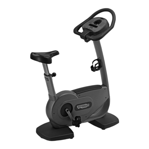
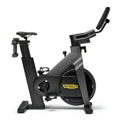
Technogym FORMA LINE BIKE FORMA DDC5 Series Owner's manual

F
FO
OR
RM
MA
A
L
LI
IN
NE
E
BIKE FORMA
(DDC5xxx…)
Technical Assistance manual
REV.1.1


The information in this manual is aimed at QUALIFIED TECHNICAL PERSONNEL, who have
been specifically trained by TECHNOGYM and been qualified to carry out fine adjustments and
start-ups, as well as major maintenance work and repairs, requiring in-depth understanding of the
equipment, how it works, its safety devices and maintenance procedures.
READ ALL THE INFORMATION IN THIS DOCUMENT VERY CAREFULLY BEFORE
CARRYING OUT ANY WORK AT ALL ON THE EQUIPMENT
THERE ARE DANGEROUS
VOLTAGE LEVELS EVEN WHEN
THE EQUIPMENT IS SWITCHED
OFF
WARNING:
The information contained in this document may be changed without prior notification.
Technogym does not issue guarantees of any kind regarding this material. Technogym will not be
held responsible for any errors contained herein or for any accidental damage or damage consequent
to the supply, services or use of this material.
This document contains proprietary information that is covered by copyright. All rights are reserved.
No part of this document may be photocopied, reproduced or translated into another language
without the prior written consent of Technogym.
Technogym™ is a trademark owned by Technogym S.p.A.
Forma Line – BIKE Forma ™ is a trademark owned by Technogym S.p.A.


Forma Line BIKE FORMA (DDC5): Technical Assistance manual - rev. 1.1
Page i
Contents
1. GENERAL WARNINGS......................................................................................................................................... 1.1
1.1. INTRODUCTION................................................................................................................................................... 1.1
1.2. USEFUL ADVICE .................................................................................................................................................. 1.1
1.3. GENERAL REGULATIONS REGARDING SERVICE WORK......................................................................................... 1.2
2. TECHNICAL SPECIFICATIONS ......................................................................................................................... 2.1
2.1. PRODUCT CODE NUMBERS .................................................................................................................................. 2.1
2.2. SERIAL NUMBER STRUCTURE............................................................................................................................. 2.2
2.3. PRODUCT CHARACTERISTICS .............................................................................................................................. 2.3
2.4. ENVIRONMENTAL CHARACTERISTICS.................................................................................................................. 2.3
2.5. COMPLIANCE WITH REGULATIONS ...................................................................................................................... 2.3
2.6. MECHANICAL CHARACTERISTICS ........................................................................................................................ 2.4
2.6.1. Bulk dimensions................................................................................................................................ 2.4
2.6.2. Packing dimensions Europe and Overseas....................................................................................... 2.5
2.7. WIRING DIAGRAM ............................................................................................................................................... 2.6
2.7.1. Powered Model (ARM Board) .......................................................................................................... 2.6
2.8. CABLES 2.7
2.8.1. CBQ Cables ...................................................................................................................................... 2.7
2.8.2. CU Cables......................................................................................................................................... 2.7
3. OPERATING PRINCIPLE..................................................................................................................................... 3.1
3.1. BLOCK DIAGRAM ................................................................................................................................................ 3.1
3.2. LED DISPLAY BOARDS........................................................................................................................................ 3.2
3.2.1. ARM Board....................................................................................................................................... 3.2
3.2.2. C-Safe Board .................................................................................................................................... 3.2
3.3. CARDIO RECEIVER BOARD ................................................................................................................................. 3.3
3.3.1. HR (Band)......................................................................................................................................... 3.3
3.4. BRAKE BOARD ................................................................................................................................................... 3.4
3.4.1. Brake Board Models......................................................................................................................... 3.5
3.5. ELECTROMAGNETIC BRAKE................................................................................................................................ 3.6
3.6. SPEED SENSOR ................................................................................................................................................... 3.6
3.7. INPUT MODULE .................................................................................................................................................. 3.6
3.8. BRAKE COMMAND .............................................................................................................................................. 3.7
3.8.1. The Mechanics.................................................................................................................................. 3.7
3.8.2. Control.............................................................................................................................................. 3.7
3.8.3. The signals involved ......................................................................................................................... 3.9
4. ACCESSORIES........................................................................................................................................................ 4.1
4.1. CONNECTION TO THE PC FOR PROGRAMMING..................................................................................................... 4.1
4.2. MONITOR PLUG FOR C-SAFE PORT ...................................................................................................................... 4.2
5. INSTALLATION INSTRUCTIONS ...................................................................................................................... 5.1
5.1. INSTALLATION .................................................................................................................................................... 5.1
5.2. HANDLING THE EQUIPMENT................................................................................................................................ 5.2
5.3. FIRST START-UP .................................................................................................................................................. 5.3
6. TROUBLESHOOTING........................................................................................................................................... 6.1
6.1. TROUBLESHOOTING MENU.................................................................................................................................. 6.2
6.1.1. Automatic Tests................................................................................................................................. 6.3
6.1.1.1. I2C Devices Test .......................................................................................................................................................... 6.3
6.1.1.2. LED Test...................................................................................................................................................................... 6.4
6.1.1.3. Serial Ports Test ........................................................................................................................................................... 6.4
6.1.2. Manual Test ...................................................................................................................................... 6.4

Forma Line BIKE FORMA (DDC5): Technical Assistance manual - rev. 1.1
Page ii
6.1.2.1. Man. Keyboard Test..................................................................................................................................................... 6.4
6.2. THE DISPLAY REMAINS OFF................................................................................................................................. 6.5
6.3. THE DISPLAY SHOWS THE MESSAGE “THE EQUIPMENT IS BLOCKED (COM)”............................................ 6.7
6.4. THE BRAKE BOARD HAS DETECTED AN ERROR................................................................................................... 6.8
6.5. THERE IS NO RESISTANCE................................................................................................................................. 6.11
6.6. THE RESISTANCE IS NOT CORRECT .................................................................................................................... 6.14
6.7. THE SPEED SIGNAL IS NOT CORRECT ................................................................................................................. 6.16
6.8. THERE IS NO HEART FREQUENCY SIGNAL.......................................................................................................... 6.18
6.8.1. HR Receiver (Heart Rate Band) ..................................................................................................... 6.18
6.9. TELEMETRIC SIGNAL OF HEART RATE IS NOT CORRECT ..................................................................................... 6.20
6.9.1. Heart Rate Band ............................................................................................................................. 6.20
7. DISMANTLING THE PARTS ............................................................................................................................... 7.1
7.1. IMPORTANT NOTE ON DISMANTLING...................................................................................................... 7.1
7.2. DISMANTLING THE CONTROL PANEL ................................................................................................................... 7.2
7.3. DISMANTLING THE ARM AND C-SAFE BOARD ..................................................................................................... 7.4
7.4. DISMANTLING THE CARDIO RECEIVER................................................................................................................ 7.6
7.4.1. HR Receiver (Band).......................................................................................................................... 7.6
7.5. DISMANTLING THE HANDLEBARS........................................................................................................................ 7.8
7.6. DISASSEMBLING THE PEDAL AND THE PEDAL LEVER WITH GUARD ...................................................................... 7.9
7.7. DISMANTLING THE GUARD................................................................................................................................ 7.10
7.8. DISMANTLING THE PULLEY UNIT WITH PEDAL CRANK ....................................................................................... 7.13
7.9. DISMANTLING THE SEAT ................................................................................................................................... 7.15
7.9.1. Dismantling the seat support .......................................................................................................... 7.15
7.9.2. Dismantling the internal bushing .................................................................................................. 7.16
7.9.3. Dismantling the seat group............................................................................................................. 7.17
7.9.3.1. Dismantling the seat upholstery................................................................................................................................. 7.17
7.9.3.2. Dismantling the handle pin ........................................................................................................................................ 7.18
7.9.3.3. Dismantling the spring and the handle....................................................................................................................... 7.19
7.9.3.4. Dismantling the handle support plate......................................................................................................................... 7.23
7.9.3.5. Dismantling the handle pin ........................................................................................................................................ 7.24
7.10.DISMANTLING THE BELT AND BELT-TENSIONER ............................................................................................... 7.26
7.11.DISMANTLING THE BRAKE AND THE FLYWHEEL UNIT....................................................................................... 7.28
7.12.DISMANTLING THE SPEED SENSOR .................................................................................................................... 7.30
7.13.DISMANTLING THE BRAKE BOARD ................................................................................................................... 7.31
7.14.DISMANTLING THE PLATFORMS ........................................................................................................................ 7.32
7.15.DISMANTLING THE INPUT MODULE .................................................................................................................. 7.33
8. ADJUSTMENTS...................................................................................................................................................... 8.1
8.1. BELT TENSION .................................................................................................................................................... 8.1
8.2. ALIGNING THE BELT............................................................................................................................................ 8.2
8.3. ADJUSTMENT OF THE PLAY ON THE SEAT COLUMN ............................................................................................. 8.3
8.4. ADJUSTING THE POSITION OF THE SPEED SENSOR................................................................................................ 8.4
8.5. ADJUSTING THE POSITION OF THE BRAKE UNIT.................................................................................................... 8.5
8.6. THE EQUIPMENT IS NOT LEVEL............................................................................................................................ 8.6
9. EQUIPMENT CONFIGURATION........................................................................................................................ 9.1
9.1.CONFIGURATION OF THE USER MENU .................................................................................................................. 9.1
9.1.1. Language .......................................................................................................................................... 9.3
9.1.2. Units of measurement ....................................................................................................................... 9.3
9.1.3. Maximum exercise time .................................................................................................................... 9.3
9.1.4. Pause time......................................................................................................................................... 9.3
9.1.5. Cooldown time.................................................................................................................................. 9.4
9.1.6. Enabling the TGS.............................................................................................................................. 9.4
9.1.7. Activating the Keyboard ................................................................................................................... 9.5
9.1.8. Modifiability of target heart rate...................................................................................................... 9.5
9.1.9. Enabling custom messages ............................................................................................................... 9.5
9.1.10. Setting the parameters to default values........................................................................................... 9.6
9.1.11. Formatting the P&P key ................................................................................................................... 9.6
9.1.12. SN ..................................................................................................................................................... 9.6


Forma Line BIKE FORMA (DDC5): Technical Assistance manual - rev. 1.1
Page iii
9.2. CONFIGURATION OF THE TECHNICAL ASSISTANCE MENU .................................................................................... 9.7
9.2.1. Low kit parameter............................................................................................................................. 9.9
9.2.1.1. Read from low kit ........................................................................................................................................................ 9.9
9.2.1.2. Write to low kit ............................................................................................................................................................ 9.9
9.2.1.3. Default Setting ........................................................................................................................................................... 9.10
9.2.1.4. Table of Configuration parameters: ........................................................................................................................... 9.10
9.2.2. Operating data................................................................................................................................ 9.11
9.2.2.1. Read from low kit ...................................................................................................................................................... 9.11
9.2.2.2. Write to low kit .......................................................................................................................................................... 9.12
9.2.2.3. Operating data............................................................................................................................................................ 9.12
9.2.3. Errors Log ...................................................................................................................................... 9.13
9.2.3.1. Read from low kit ...................................................................................................................................................... 9.13
9.2.3.2. Reset errors ................................................................................................................................................................ 9.13
9.2.3.3. COM.Fault ................................................................................................................................................................. 9.14
9.2.3.4. Display errors............................................................................................................................................................. 9.14
9.2.4. Standard settings ............................................................................................................................ 9.15
9.2.5. Low kit menu................................................................................................................................... 9.15
9.2.5.1. Low kit version .......................................................................................................................................................... 9.16
9.2.5.2. Config. registers......................................................................................................................................................... 9.16
9.2.5.3. Low Kit fault code ..................................................................................................................................................... 9.16
9.2.6. High kit version .............................................................................................................................. 9.16
9.2.7. BOOT version ................................................................................................................................. 9.17
9.2.8. Key Reader Version ........................................................................................................................ 9.17
10. SCHEDULED MAINTENANCE ......................................................................................................................... 10.1
10.1.ROUTINE MAINTENANCE.......................................................................................................................... 10.1
10.2.SPECIAL MAINTENANCE ........................................................................................................................... 10.1
11. APPENDIX............................................................................................................................................................. 11.1
11.1.TOOLS TO BE USED ........................................................................................................................................... 11.1

Forma Line BIKE FORMA (DDC5): Technical Assistance manual - rev. 1.1
Page iv
Page blank.

Forma Line BIKE FORMA (DDC5): Technical Assistance manual - rev. 1.1
Page 1.1
1. GENERAL WARNINGS
1.1. INTRODUCTION
This document has been prepared specifically for Technogym After Sales Service with the aim of
providing authorised personnel with the information for carrying out maintenance and repair
operations in the correct manner. A thorough understanding of the technical data contained herein is
absolutely fundamental for the operator to achieve the highest level in professional training.
In order to make the reading more readily understandable, the paragraphs have illustrations and
diagrams which highlight the specific subject matter.
This manual includes informative notes with specific meanings:
DANGER: non observance may result in accident or injury.
WARNING: non observance may cause damage to the machine.
CAREFUL: Information about the operation in progress.
Observation about the operation in progress.
1.2. USEFUL ADVICE
Technogym advises you to program your technical assistance task in the following way:
•Make a careful assessment of the impressions given by the Customer regarding the equipment's operating
faults and formulate some appropriate questions to clarify the symptoms relating to the defect.
•Be clear in your diagnosis of the reasons for the fault. You can pick up the basic theoretical
information from this manual, but this needs to be bolstered by your own personal experience
and by taking part in the training courses organised periodically by Technogym.
•Plan the repair work in a rational manner so as to avoid wasting any time, e.g. collecting spare
parts, preparing tools and equipment etc.
•Gain access to the part that needs to be repaired and limit yourself to the essential operations.
On this point, it will be extremely helpful if you consult the dismantling sequences shown in this
manual.

Forma Line BIKE FORMA (DDC5): Technical Assistance manual - rev. 1.1
Page 1.2
1.3. GENERAL REGULATIONS REGARDING SERVICE WORK
1. Always mark components or positions which might easily be confused with each other during
re-assembly.
2. Use original Technogym spare parts and recommended brand lubricants.
3. Use special tools when specified to do so.
4. Consult the Technical Newsletters as they might contain more up-to-date details on regulation
and servicing procedures compared to those in this manual.
5. Before undertaking any work, check that the recommended tools are available and that they are
in good condition.
6. With regard to the procedures given in this manual, only use the tools that have been indicated.
Tool measurements in this manual are expressed in mm.

Forma Line BIKE FORMA (DDC5): Technical Assistance manual - rev. 1.1
Page 2.1
2. TECHNICAL SPECIFICATIONS
2.1. PRODUCT CODE NUMBERS
The equipment code numbering takes into account all the possible variants and available options for
the products. The equipment code number, which does not contain the Serial Number, is made up of
16 alphanumeric characters as follows:
Characters
Description
Values and meaning
1,2,
Type of Line
DD = FORMA LINE
3,
Type of equipment
C = Bike Forma
4,
Model
5= 500
5,
Type of energy supply used
3= Powered
6,
Type of Display
L= LED
7,
Built-in devices
N= None
8, 9,
Frame Colour,
AN = Anthracite
10, 11, Upholstery Colour,
00 = none
NA = Nero
12,
Guard Colour,
R= Renault Grey
13,
Type of standard TV,
0= none
14,15, Language,
BR = Portuguese
DA = Danish
DE = German
ES = Spanish
FR = French
IT = Italian
JP = Japanese
NL = Dutch
RU = Russian
TR = Turkish
UK = British English
US = American English
ZH = Chinese
16.
Type of packing.
S= Overseas
For example, a possible code number could be the following:
DD
C
5
3
L
N
AN
NA
R
0
UK
S

Forma Line BIKE FORMA (DDC5): Technical Assistance manual - rev. 1.1
Page 2.2
2.2. SERIAL NUMBER STRUCTURE
The Serial Number is made up of 14 alphanumeric characters as follows:
Characters
Description
Values and meaning
1,2,3,4,5,6, Type of product,
DD = FORMA LINE
C = Bike Forma
5= 500
3= Powered
7,8,
Year of production,
L= LED
9,10,11,12,13,14.
Progressive.
11 = 2011
For example, a possible code number could be the following:
DD
C
5
3
L
11
000001

Forma Line BIKE FORMA (DDC5): Technical Assistance manual - rev. 1.1
Page 2.3
2.3. PRODUCT CHARACTERISTICS
Bike Forma
Power supply:
100-240Vac
50-60Hz
Energy consumption:
Max 35W (50VA)
Consumption
in Stand-by:
9W
Resistance:
30-500Watt (a 70 rpm)
Difficulty Levels:
1 - 25
Max. user weight:
180Kg – 397lb
Seat height adjustment:
SI
Steps of seat height adjustment:
12,5mm
HR Monitoring:
Telemetry
Plug & Play System:
SI
Total number of programs:
3:
Quick start
Goal
CPR
Languages available:
13: UK English, US English, Italian, German,
Spanish, French, Dutch, Portuguese, Japanese,
Chinese, Russian, Turkish, Danish
2.4. ENVIRONMENTAL CHARACTERISTICS
Temperature
In operation
from 5° to 35° C
In storage
from -10° to 70° C
Dampness
In operation
from 30% to 80% without condensation
In storage
from 5% to 85% without condensation
2.5. COMPLIANCE WITH REGULATIONS
Directives
EUROPE
EMC
EN55014-1
EN55014-2
ELECTRICAL safety
EN60335-1
MECHANICAL safety
EN957-1
EN957-2
In addition:
•Electrical insulation class: Class I;
•Protection rating: IP20.

Forma Line BIKE FORMA (DDC5): Technical Assistance manual - rev. 1.1
Page 2.4
2.6. MECHANICAL CHARACTERISTICS
MECHANICAL CHARACTERISTICS
Length (mm | in)
1216mm –48”
Width (mm | in)
600mm –24”
Height (mm | in)
1338mm –53”
Total weight (kg | lbs)
61Kg –134.5lbs
2.6.1. BULK DIMENSIONS

Forma Line BIKE FORMA (DDC5): Technical Assistance manual - rev. 1.1
Page 2.5
2.6.2. PACKING DIMENSIONS EUROPE AND OVERSEAS

Forma Line BIKE FORMA (DDC5): Technical Assistance manual - rev. 1.1
Page 2.6
2.7. WIRING DIAGRAM
2.7.1. POWERED MODEL (ARM BOARD)

Forma Line BIKE FORMA (DDC5): Technical Assistance manual - rev. 1.1
Page 2.7
2.8. CABLES
The colour of the cables may change: in particular, refer to the Pin Out.
2.8.1. CBQ CABLES
CBQ-13: C-Safe Board Cable (Only LED)
(ARM Board - C-Safe Board)
ARM Board
CN8
Signal Colour
C-Safe Board
CN1
1
Digital #1
Flat cable
1
…
…
…
…
14
Digital #14
Flat cable
14
2.8.2. CU CABLES
CU195: Power supply cable for High Kit and Low Kit
(Brake Board - CPU/ARM Board)
Brake Board
CN1
Signal Colour
ARM Board: CN1
CPU Board: CN15
1
GND
Yellow/Green
Faston/Eyelet
2
GND -12V
White
2
3
GND -5V
Yellow
3
4
sensing GND + 5V
Pink
4
5
n.c.
-
5
6
+ 12 Vdc
Brown
6
7
+ 5 Vdc
Green
7
8
sensing + 5V
Grey
8
CU196: Serial communication cable for High Kit and Low Kit
(Brake Board - CPU/ARM Board)
Brake Board
CN3
Signal Colour
ARM Board:CN9
CPU Board:CN18
1
n.c.
Orange-White
1
2
n.c.
Orange
2
3
n.c.
Green-White
3
4
n.c.
Blue
4
5
n.c.
Blue-White
5
6
n.c.
Green
6
7
485 TX/RX +
Brown-White
7
8
485 TX/RX -
Brown
8

Forma Line BIKE FORMA (DDC5): Technical Assistance manual - rev. 1.1
Page 2.8
CU208: Cable for HR Cardio Receiver
(ARM Board - HR Receiver)
ARM Board: CN3 Signal Colour
HR Receiver:
CN1
1
Power supply + 5Vdc
White
2
7
Impulse (beat to beat)
Brown
4
8
Gnd
Green
1
CU309: Cable for 100/220V internal power supply signal
(Input module - Brake Board)
Input Module Signal Colour
Brake Board
CN4
N
NEUTRAL
Light Blue
1
F
PHASE
Brown
3
T
Earth cable
Yellow/Green
5
CU504: Brake power supply cable
(Brake Board - Brake - Speed sensor)
Brake Board
CN2
Signal Colour Brake
Speed Sensor
(magnetic PK)
1
Brake power supply +
Brown
Faston
-
2
Brake power supply -
White
Faston
-
3
R.P.M.Sens.
Yellow
-
Faston
4
GND-RPM Reference
Black
-
eyelet
5
n.c.
-
-
-
6
n. c.
-
-
-

Forma Line BIKE FORMA (DDC5): Technical Assistance manual - rev. 1.1
Page 3.1
3. OPERATING PRINCIPLE
3.1. BLOCK DIAGRAM
The block diagram for the equipment is represented in the following figure:

Forma Line BIKE FORMA (DDC5): Technical Assistance manual - rev. 1.1
Page 3.2
3.2. LED DISPLAY BOARDS
3.2.1. ARM BOARD
The Display includes a single board which contains the CPU, an ARM microprocessor, the logic for
its operation and the EPROM FLASH containing the equipment's work program, and also acts as a
connection centre for all the display components and a connection point with the Brake Board.
The main functions of the board are:
manage and process the signals from:
(1) Keyboard;
(2) HR Receiver:
(3) C-Safe Board;
distribute on the display the supplies it receives from the Brake Board;
exchange with the Brake Board the piloting commands for the brake on the RS-485 serial line;
manage the LEDs and the 7 display segments to provide feedback on operating.
There are some signal LEDs on the board:
LED Name
Colour
Description
LED1 GREEN
if ON, the +12Vdc power supply, provided by the Brake Board, is
reaching the board correctly.
LED2 YELLOW
if ON, the +5Vdc power supply, provided by the Brake Board, is
reaching the board correctly.
3.2.2. C-SAFE BOARD
This is the board that makes available 1 connector for communication between the outside world
and the C-Safe compatible devices, such as: Cardio Theater readers. This connector is located at the
back of the display.
Using a special cable, this connector can be interfaced with an external PC to program the FLASH
memory.
Table of contents
Other Technogym Exercise Bike manuals

Technogym
Technogym GROUP CYCLE Installation and user guide

Technogym
Technogym spin trainer User manual

Technogym
Technogym BIKE EXC 700 LED User manual

Technogym
Technogym EXCITE BIKE User manual

Technogym
Technogym Top 600 XTPRO User manual

Technogym
Technogym BIKE XT User manual

Technogym
Technogym GROUP CYCLE User manual

Technogym
Technogym BIKE ARTIS User manual

Technogym
Technogym New Bike EXCITE Plus How to use

Technogym
Technogym Bike Excite Live User manual