TECLOCK SSI-650 User manual

User’s Manual
Bluetooth Digital Indicator 1/10000
Type : SSI-650
Features
➢Resolution :0.0001mm
➢Protection :IP54
➢Wireless Communication :Bluetooth
1
Q-143-1-J ver1.2

Description
2
月
36.6
56.7
66.1
50.5
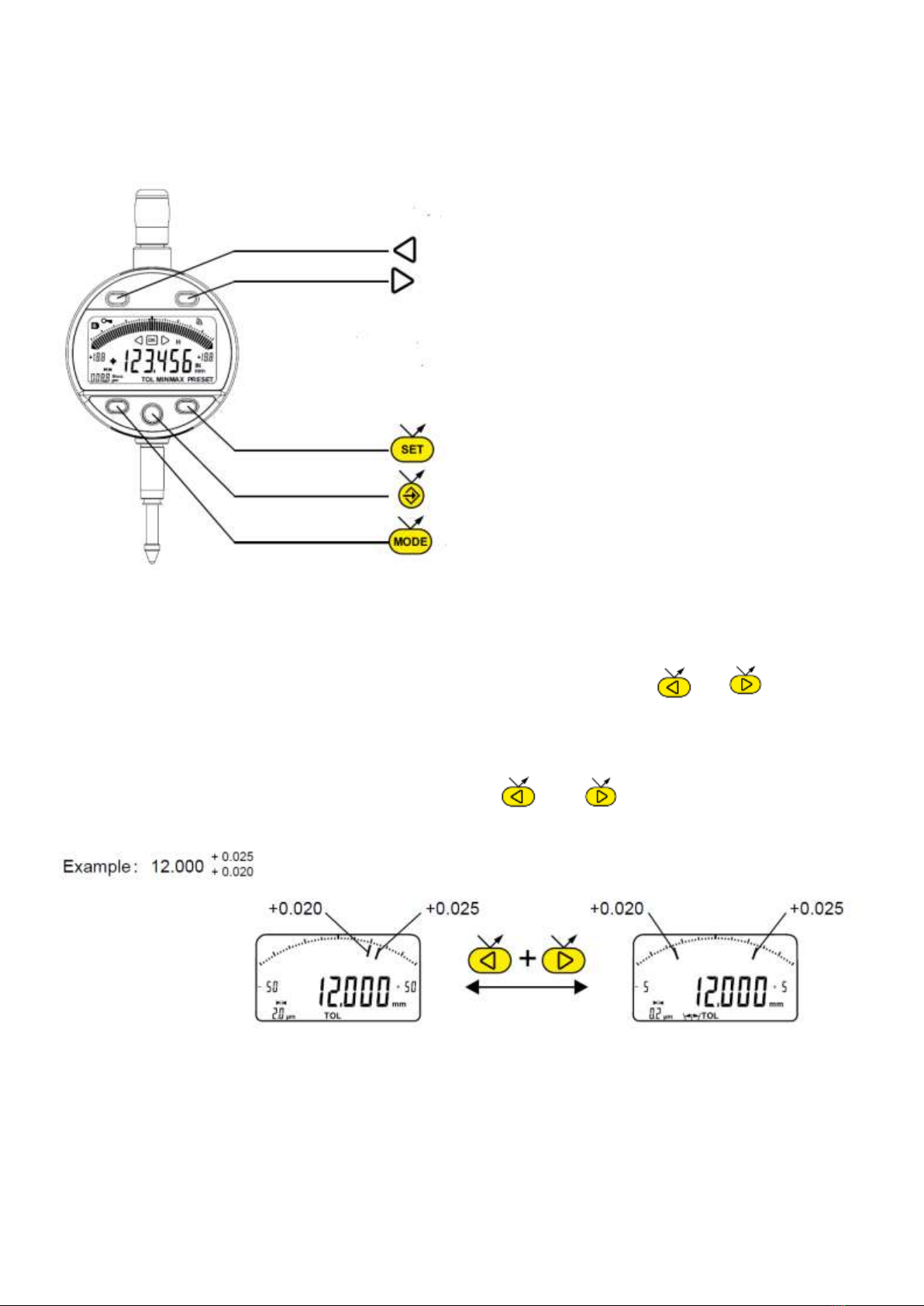
①MODE button
②SET button
③“Favorite” button
④◁button
⑤▷ button
⑥Clamping shaft Ø8 or 3/8”
⑦Contact point Ø2 / M2.5 or 4-48-UNF
⑧Lifting cap
⑨Slot for Proximity cable
⑩Slot for battery or Power cable
⑪Low battery
⑫+ / - Indicator
⑬Keypad lock
⑭7-digit display
⑮Hold measured value
⑯Send data
⑰Measurement units (mm / INCH)
⑱Preset mode
⑲Analogue scale
⑳Lower limit exceeded
㉑Upper limit exceeded
㉒Tolerance mode
㉓Analogue scale lower limit
㉔Analogue scale upper limit
㉕Unit and value of analogue scale
㉖Tolerance mode
㉗MIN/MAX/DELTA mode
㉘Multiplier
㉙Bluetooth connection
㉚Symmetrical tolerances
Diagram for rear fixings

★Installing and replacing the battery
1. Operating features of the instrument
①Button
The instrument has two operating modes: basic functions (direct access) and advanced functions.
In addition to the configuration functions, available access to the MIN, MAX and DELTA mode, or
display of tolerances (see chaps. 3 and 4)
②Button
The <favorite> button gives direct access to the function used most often (see chap. 9).
③Button
Sets a Preset value, resets the MIN/MAX mode, verifies a selection, and controls switching off the
instrument. By default, SIS mode enables automatic switch-off with no loss of origin (see chap. 11).
④Button
With the «Left and Right» buttons, the user may change the extent of the analogue scale as well as
enter the values of the nominal dimension and tolerance limits. (see chap. 6.2)
⑤Serial communication(Bluetooth/RS232/USB)
It is possible to activate or de-activate certain functions of the instrument via serial communication
(see chap. 13).
Data transmission parameters are 4800bps,7bits,even parity, and 2 stop bits.
2. Start
Press any button.
For a Bluetooth connection (see chap. 5).
3
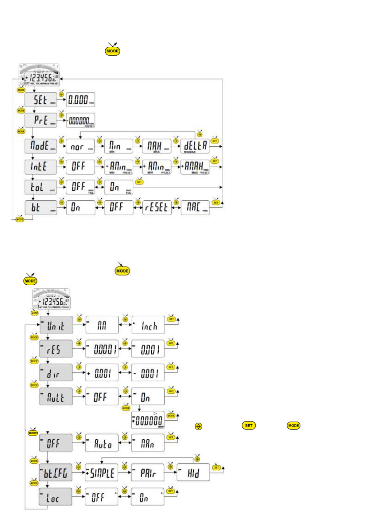
3. Basic functions
Each short press on gives direct access to the basic functions :
4. Advanced functions
Prolonged pressure (>2s) on gives access to the advanced functions. Then, each short press on
accesses the required function:
・Assign NORMAL/MIN/MAX/DELTA mode
(see chap. 5)
・Bluetooth ON/OFF
・Reset Pairing mode
・Display the MAC add.
・Inputting a Preset value
(see chap. 7)
SEt
PrE
ModE
MAX
dELtA
nor
Min
toL
OFF
On
bt(Bluetooth)
On
OFF
rESEt
MAC
IntE
+AMin
+AMAX
OFF
-AMin
・Normal mode : Zero reset
・Min (Max) mode : Preset on the measured
min (max) value
・2 points measurement (Dynamic preset)
(see chapter 11)
・Tolerance display
(inputting tolerance limits, see chap. 6)
Assign Button lock mode(OFF/ON)
Lock mode lock and .
To unlock, Press for 5 sec.
Assign measurement unit(mm/inch)
HId
bt.CFG
SIMPLE
PAIr
Loc
OFF
On
Assign resolution (0.0001mm/0.001mm)
Assign measurement direction (+/-)
Assign multiplier mode OFF/ON
Assign the multiplier value
next digit
0~9
Save Mult.
Activates/deactivates the automatic switch-off
Auto(Automatic):Activates/Man:(Manual)De-activates
Assign Bluetooth profile(Config.)
SIMPLE/Pair/HID
Unit
MM
Inch
rES
dir
MuLt
OFF
On
Auto
OFF
MAn
4
5. Work in MINIMUM, MAXIMUM and DELTA mode :
In this operating mode, the digital display stores the MIN, MAX or DELTA value. On the other hand, the
analogue scale always indicates the current measured value.
- A short press on resets the MIN/MAX stored value (CLEAr)
- A long press (>2s) on assigns the Preset value to the position of current measurement.
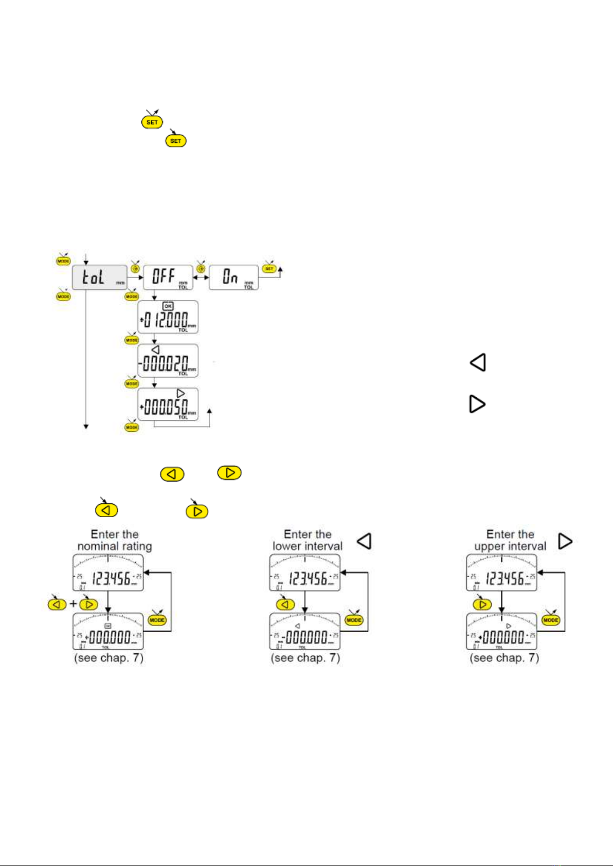
6. Inputting (or modifying) tolerance limits
The tolerance limits are defined by introducing lower and upper intervals, compared to the nominal rating.
Two methods are available :
6.1 Using the TOL mode
6.2 Use of the buttons and :
It is also possible to enter or modify the nominal value or the tolerance limits by prolongedly pressing
(>2s) the and / or button :
Note :
- It is also possible to display the tolerance limits when the instrument is operating in MIN, MAX or DELTA
mode.
- If no tolerance limits have been defined by the user, the instrument will only display the tolerance limit
indicators but will not turn on the indicator lights (red - green - yellow).
- In case of measuring internal ratings, you can cross the indicators (red and yellow) by reversing the
order of entering the tolerance intervals (upper interval < lower interval).
Input the nominal value (see chap. 7)
Input the lower tolerance limit (see chap. 7)
Input the upper tolerance limit (see chap. 7)
5
7. Entering a numeric value
To enter or modify a numeric value (Preset, nominal ratings, tolerance intervals or multiplication factor),
you can proceed in two ways :
8. Scale the analog display
The user may change the analogue display’s scale value by shortly pressing or .
8.1 Centering function of the analogue scale
When the tolerance limits are asymmetric with respect to the nominal ratings, it is possible to realign them
to the analogue scale, by a short simultaneous press on and .
6
7.1 Increases / decreases the current value :
Decreases the current value
Increases the current value
Note: - the scanning speed increases with a long press on the button
- save the value with one of the three lower buttons
7.2 Entering digit by digit :
Increase of the selected digit
Selection of the next digit
Save the value
Asymmetric tolerance limits
Realigned tolerance limits

9. Operation via Bluetooth
9.4. Bluetooth Connection :
1° Activate Bluetooth compatible software and hardware (Master: PC, Display Unit).
2° Start the instrument. By default the Bluetooth® module is active and the instrument is available for
connection (advertising mode).
3° If no connection is established during the advertisement period reactivate the Bluetooth® module
using the bt / On menu.
4° Instrument is ready to communicate (connected mode.)
9.5. Only with paired profile:
Pairing with master is automatically done at first connection.
To connect the instrument to a new master (new pairing), pairing information on the instrument must be
cleared using the bt/ rESEt menu.
9.6. Bluetooth Specifications:
7
9.1. HID mode(External Key board mode)
①Set HID mode by Advanced function.
②Set BT On mode by Advanced function.
③Reset Bluetooth mode by Basic function.
④Pairing connection the instrument to the PC.
(Instrument name:S_Dial Work HID)
⑤Send the measured data by the DATA button.
9.2. Pair mode
①Set Pair mode by Advanced function.
②Set BT On mode by Advanced function.
③Reset Bluetooth mode by Basic function.
④Pairing connection the instrument to the PC.
(Instrument name:SY289)
⑤Send the measured data by the DATA button.
9.3. Bluetooth configuration
Items Specification
Frequency band 2.4GHz
Modulation GFSK
Max output power Class3(1mW)
Range
≦15m(open space),1-5m(industrial environment)
Version Bluetooth4.*
Display status Operating mode
off Bluetooth disconnected
blinkinng Bluetooth advertising
on Bluetooth connected
reset : clear pairing information
MAC : display the MAC address
Simple : profile without pairing
Pair : paired and secured profile
HID : virtual keyboard

10. Favorite key
The «favorite» key gives direct access to a predefined function, and can be configured according to the
needs of the user. In order to assign a function to the «favorite» key, give a prolonged press on ,
and then select the required function :
Validation of selection: By a prolonged press on or a short press on or .
Note : - A function can also be assigned via RS232 using the command <FCT + Function No.>
(FCT 0..9 A..F) example : Toggle unit = <FCT7>, multiplication factor = <FCTA>.
11. Adjustment and use of IntE dynamic measuring mode
Certain applications need to adjust the instrument to the MIN (or MAX) measured value. In this case,
proceed as follows :
11.1 Adjustment of the instrument
- Enter a Preset value corresponding to the actual size of the standard (see chap. 3)
- In the IntE menu, select the mode -AMIN (automatic selection of DIR- and mode MIN) or +AMIN
(automatic selection of DIR+ and mode MIN) or +AMAX (automatic selection of DIR+ and mode MAX)
depending on application
- Make a standard measurement (going through the turnaround point)
- Adjust the instrument by selecting the SEt mode and pressing on the button (see chap. 3)
- The instrument is adjusted and ready to measure.
11.2 Measure
- Make the measurements going through the turnaround point. The digital display stores and displays
the MIN (or MAX) measured value.
- Before each new measurement, reset the measured value by a short press on .
Examples :
8
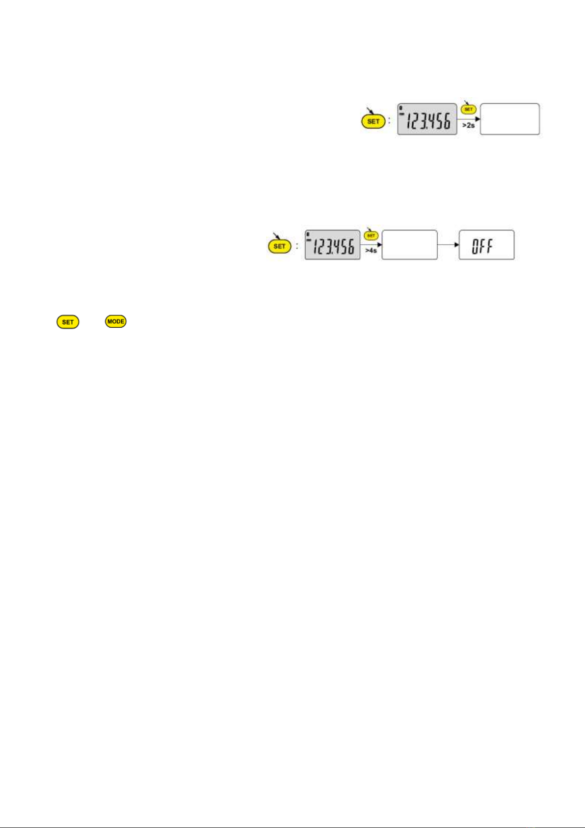
12. Switching off
The dial gauge goes automatically into stand-by if not used for 10 minutes, unless automatic switch-off
mode has been turned off (see Chap. 4, advanced functions).
Stand-by mode can be forced by a prolonged press (> 2 sec) on
In stand-by mode, the value of the origin is retained by the sensor (SIS mode), and the instrument
automatically restarts with any movement of the measurement probe, RS command,
Bluetooth®
request
or press on button.
The instrument can be switched off completely for a long period of non-use, but this will necessitate a
zero reset on restart (the origin will be lost) :
- Prolonged press (>4 sec) on
13. Re-initializing the instrument
The initial instrument settings can be restored at any time by a prolonged press (>4 sec) simultaneously
on and until the message rESEt is displayed.
14. Connecting the instrument
The instrument can be connected to a peripheral via a Proximity (RS or USB), Power (RS or USB) cable
or Bluetooth®. See page 3 for connecting the Power cable.
Measured values can be transmitted and the instrument driven using predefined commands (see chap. 10
for a list of the main commands).
Note : - In Tolerance mode, the tolerance limit lights remain lit only for a few seconds while the
measurement stabilities. On the other hand, they will remain lit continuously if the instrument is
connected to, and powered by, the Power RS (USB) cable.
15.Maintenance
Carefully dry all mechanical parts of the instrument after contact with liquids to ensure proper
operation and avoid corrosion.
Don’t use aggressive products (alcohol, trichloroethylene or others) to clean plastic parts.
Don’t expose the instrument to direct sunlight, heat or humidity.
9
16. Serial communication commands
10
Selection and configuration Interrogation
CHA+ / CHA-
Assign measurement direction
CHA+:positive sense / CHA-:negative sense
CHA?
Measurement direction?
Response : CHA+ / CHA-
FCT0 / FCT1 / … / FCTA / … / FCTF
Assign «favourite» function FCT? «favourite» function ?
Response : FCT0~FCTF
MM / IN
Assign measurement unit
MM:mm/IN:inch UNI? Measurement unit active?
Response : MM/IN
KEY0 / KEY1
Assign Keypad Lock
KEY0:Lock/KEY1:Unlock KEY? Keypad locked?
Response : KEY0/KEY1
MUL +/-xx.xxxx Assign the multiplier value MUL?
Multiplier value?
Response : +/-xx.xxxx
PRE +/-xxx.xxx Assign preset value PRE?
Preset value?
Response : +/-xxx.xxx
STO1 / STO0
Assign Hold mode
STO1:ON / STO0:OFF STO?
Status of HOLD function?
Response : STO1/STO0
TOL1 / TOL0
Assign Tolerance mode
TOL1:ON /TOL0:OFF TOL?
Status of Tolerance mode?
Response : TOL1/TOL0
REF1 / REF2
Change active reference
Two tolerance values are REF1 or REF2
REF?
Active Reference ?
Response : REF1/REF2
ECO1 / ECO 0
Assign Economic mode
ECO1:ON / ECO0:OFF ECO?
Current economic mode?
Response : ECO1/ECO0
INTE1 / INTE0
Assign 2 points measurement mode
INTE1:ON / INTE0:OFF
INTE ?
2 points mode ?
Response : INTE1/INTE0
LCAL dd.mm.yy Modify last calibration date LCAL?
Date of last calibration?
Response : dd.mm.yyyy
NCAL dd.mm.yy Modify next calibration date NCAL?
Date of next calibration?
Response : dd.mm.yyyy
NUM x...x (up to 20 chars) Modify the instrument number NUM?
Instrument number?
Response : NUM x...x
MIN /MAX /DEL /NOR
Assign MIN, MAX, Delta, Normal mode
MIN:Minimum/MAX:Maximum/DEL:Delta=MAX-MIN/
NOR:Normal=Current value
MOD?
Active mode (MIN, MAX, Delta or Normal)?
Response : MIN/MAX/DEL/NOR
AOFF1 /AOFF0
Activates/deactivates the automatic switch-off
AOFF1:Activate/AOFF0:De-activate
AOFF?
Status of the automatic switch-off
Response:AOFF1/AOFF0
CFGBAR NOR / CFGBAR MAX
Assign Bargraph display
CFGBAR NOR:Normal bargraph/
CFGBAR MAX:Keep Bargraph on Max value
CFGBAR?
Bargraph configuration?
CFGBAR NOR/CFGBAR MAX
FACT1 / FACT2 / FACT5 / FACT10
Assingn analogue scale factor
FACT1:1scale=1digit/FACT2:1scale=2digits/
FACT5:1scale=5digits/FACT10:1scale=10digits
FACT?
Status of the analogue scale factor?
Response : FACT1/FACT2/FACT5/FACT10
RES1 / RES2 / RES3
Change of resolution
RES1:0.0001mm/RES2:0.001mm/RES3:0.01mm
RES?
Status of the current resolution?
Response : RES1/RES2/RES3
TOL +/-xxx.xxx +/-yyy.yyy
Inputting current tolerance limits
x:lower tolerance limit/y:upper tolerance limit
?
Current value (the displayed value)?
Response : +/-zzz.zzz ⇒current value
in the case of Tol mode
=+/-zzz.zzz ⇒current value
<+/-xxx.xxx ⇒lower tolerance limit
>+/-yyy.yyy ⇒upper tolerance limit
CLE Reset(Clear) of MIN, MAX or Delta SET?
Main instrument parameters?
Response : CHA+/CHA-,MM/IN,X1/X2/X5,
RES1/RES2/RES3,MIN/MAX/DEL/NOR,
STO0/STO1,KEY0/KEY1,BAT1/BAT0
UNI1 / UNI0
Activate / de-activate UNIT command(MM/IN)
UNI1:ON/UNI0:OFF
ID?
Instrument identification code?
Response : SYxxx
OUT1 /OUT0
Activate / de-activate continued data transmission
OUT1:ON/OUT0:OFF
BAT?
Status of Battery?
Response : BAT1: OK/ BAT0: low battery
PRE ON / PRE OFF Activate / de-activate Preset function(PRE command) VER?
Version No. and date of firmware
Response : Vx.x DD.MM.YYYY
ANA ON / ANA OFF Activate / de-activate the analogue scale MAC?
Bluetooth® MAC address?
Response :XXX…XXX(up to 12 chars)
PRE Recall Preset value
SET Zero reset
SBY xx xx number of minutes before stand-by
BT1 / BT0
Activate/de-activate Bluetooth® module
BT1:ON/BT0:OFF
BTRST Reset Bluetooth pairing information
OFF Switch-off (wake up using a button or RS)
RST Reset the instrument
SBY Put instrument in stand-by mode(SIS)
FAC RST Reset (Restores the factory parameters)
TOL +/-nnn.nnn +/-xxx.xxx +/-yyy.yyy
(In the case of SSI-650)
Inputting current tolerance limits
n :nominal value /
x :lower tolerance limit/y :upper tolerance limit

17. Specifications
18.Description of Bluetooth® module:
This module is based on Nordic Semiconductor nRF8001 μBlue Bluetooth Low Energy Platform. The
nRF8001 is a single chip transceiver with an embedded baseband protocol engine, suitable for ultra-low
power wireless applications conforming to the Bluetooth Low Energy Specification contained within v4.0
of the overall Bluetooth specification. The nRF8001, used in the current revision of ISP091201, is a
product using a ROM for the baseband protocol engine.
19.Certification
11
Items Specification
Measuring range 12.5 mm
Resolution 0.0001 mm
Measureing force 0.65~0.9 N
Indication Error 1.8 µm
Repeatabirity 0.5 µm
MAX. speed of travel 1.7 m/s
No. of measurements /second Normal mode : up to 10 meas/s , MIN/MAX mode : 20 meas/s
Data output Bluetooth/USB/RS232
Data output parameter 4800bauds,7bits,parity,2stop bits
Battery life about 6 months(general using)
Working temperature 5~40℃
Storage temperature -10~60℃
Weight 119g
EMC EN61326-1
IP specification IP54
Battery CR2032
contains bluetooth module ISP091201D
Region Certification
USA FCC ID : 2AAQS-ISP091201
Canada IC : 11306A-ISP091201
Brazil Anatel : 0516-14-4534
Korea South MSIP-CRM-iNs-ISP091201
Mexico IFT : RCPSYIS14-0655
Japan 001-A06167
Taiwan CCAH18LP2040T6
EU
India WPC : ETA-1003/2-17-/RLO(WR)

CERTIFICATE OF CALIBRATION
We hereby certify that this product has been calibrated and found to be in accordance with the
applicable NATIONAL STANDARDS and TECLOCK STANDARDS, Equipment used in this calibration
has traceable accuracy to the NATIONAL LENGTH and FORCE STANDARD.
Notice for use
Be sure to conduct a routine check for this product according to the purpose of use before use. This
product is precision instrument, periodically considering frequency of use, environmental conditions and
method of use.
It is not guaranteed for the performance of this product, which has been repaired or disassembled by
other than TECLOCK.
For appearance and other design improvement, this products
subject to change without advance notice.
TECLOCK Corporation
TECLOCK SmartSolutions Corporation
http://www.teclock.co.jp
HEAD OFFICE
2-10-3 MARUTA-CHO, OKAYA-SHI, NAGANO-KEN 394-0042
PHONE:81-266-22-4912, FACSIMILE:81-266-22-4914
E-mail:[email protected]
Table of contents
Other TECLOCK Measuring Instrument manuals


