Tecnoautomazione T3 300 Series User manual

T3 SERIES
T3 SERIES 300
T3 SERIES 400
T3 SERIES 500
T.A. Tecno Automazione s.r.l. - Via Vicinale snc - 03018 - Paliano - (FR) - Italy - Tel +39 0775 533677 - Fax +39 0775 533299 - [email protected] - www.tecnoautomation.com - www.tecnoautomazione.com
MADE IN ITALY
A) Dichiarazione per AEE Domesche senza Pile o Accumulatori portali
INFORMAZIONE AGLI UTENTI DI APPARECCHIATURE DOMESTICHE O PROFESSIONALI
Ai sensi dell'art. 26 del Decreto Legislavo 14 marzo 2014, n. 49 "Auazione della Direva 2012/19/UE sui rifiu di apparecchiature eleriche ed eleroniche (RAEE)"
Il simbolo del cassoneo barrato riportato sull'apparecchiatura o sulla sua confezione indica che il prodoo alla fine della propria vita ule deve essere raccolto separatamente dagli altri rifiu per permeerne un adeguato traamento e
riciclo. L'utente dovrà, pertanto, conferire gratuitamente l'apparecchiatura giunta a fine vita agli idonei centri comunali di raccolta differenziata dei rifiu elerici ed eleronici, oppure riconsegnarla al rivenditore secondo le seguen
modalità:
- per apparecchiature di piccolissime dimensioni, ovvero con almeno un lato esterno non superiore a 25 cm, è prevista la consegna gratuita senza obbligo di acquisto presso i negozi con una superficie di vendita delle apparecchiature
eleriche ed eleroniche superiore ai 400 mq. Per negozi con dimensioni inferiori, tale modalità è facoltava.
- per apparecchiature con dimensioni superiori a 25 cm, è prevista la consegna in tu i pun di vendita in modalità 1contro1, ovvero la consegna al rivenditore potrà avvenire solo all'ao dell'acquisto di un nuovo prodoo equivalente,
in ragione di uno a uno.
L'adeguata raccolta differenziata per l'avvio successivo dell'apparecchiatura dismessa al riciclaggio, al traamento e allo smalmento ambientalmente compabile contribuisce ad evitare possibili effe negavi sull'ambiente e sulla
salute e favorisce il reimpiego e/o riciclo dei materiali di cui è composta l'apparecchiatura.
Lo smalmento abusivo del prodoo da parte dell'utente comporta l'applicazione delle sanzioni di cui alla corrente normava di legge.
Tecno Automazione ha scelto di aderire a Consorzio Remedia, un primario Sistema Collevo che garansce ai consumatori il correo traamento e recupero dei RAEE e la promozione di poliche orientate alla tutela ambientale.
For private households: Informaon on Disposal for Users of WEEE This symbol on the product(s) and / or accompanying documents means that used electrical and electronicequipment (WEEE) should not be mixed with general
household waste. For proper treatment, recovery and recycling, please take this product(s) to designated collecon points where it will be accepted free of charge. Alternavely, in some countries, you may be able to return your
products to your local retailer upon purchase of an equivalent new product. Disposing of this product correctly will help save valuable resources and prevent any potenal negave effects on human health and the environment,
which could otherwise arise from inappropriate waste handling. Please contact your local authority for further details of your nearest designated collecon point. Penales may be applicable for incorrect disposal of this waste, in
accordance with you naonal legislaon. For professional users in the European Union If you wish to discard electrical and electronic equipment (EEE), please contact your dealer or supplier for further informaon. For disposal in
countries outside of the European Union This symbol is only valid in the European Union (EU). If you wish to discard this product please contact your local authories ordealer and ask for the correct method of disposal.
T3 SERIES 300/400/500
T3 SERIES 400/500
T3 SERIES 500
T.A. Tecno Automazione s.r.l. - Via Vicinale snc - 03018 - Paliano - (FR) - Italy - Tel +39 0775 533677 - Fax +39 0775 533299 - [email protected] - www.tecnoautomation.com - www.tecnoautomazione.com

CONDIZIONI OTTIMALI DI INSTALLAZIONE
SUITABLE CONDITIONS OF INSTALLATION - CONDITIONS POUR UNE CORRECTE INSTALLATION
OPTIMALE BEDINGUNGEN VON INSTALLATION - CONDICIONES IDEALES PARA LA INSTALACIÓN
Fig. 2
112
82
52
BR_A
Fig. 10 A
D
B
Fig. 6
P3 P4
Fig. 4
P1 P2
Fig. 7
BR_A BR_B
PR_A
GR_A
dx dx
sx sx
Fig. 8
Fig. 12
AA
DD
BB
CC
Fig. 3 A
B
T3 300
T3 400
T3 500
A B C
195 195 390
245 245 490
145 145 290
Max. 90°
Max. 120°
Fig. 5
Fig. 11
Fig. 9
BR_C
PR_A
GR_A
2 cm
T.A. Tecno Automazione s.r.l. - Via Vicinale snc - 03018 - Paliano - (FR) - Italy - Tel +39 0775 533677 - Fax +39 0775 533299 - [email protected] - www.tecnoautomation.com - www.tecnoautomazione.com

CRITERI DI SICUREZZA
1Prima di iniziare qualsiasi operazione di installazione è assolutamente necessario Nell’ ipotesi che ciò sia di difficile attuazione procedere come segue;
leggere tutto il presente manuale. - Misurare la quota D (distanza tra l’asse delle cerniere e lo spigolo del pilastrino).
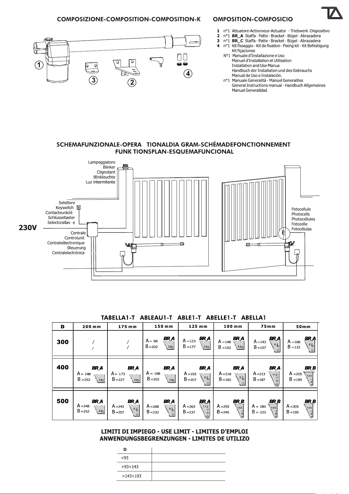
2Verificare che le prestazioni dell’attuatore acquistato corrisponda alle vostre - Consultare la tabella 1 e seguire la riga corrispondente al modello di attuatore
esigenze di installazione. acquistato fino ad incrociare la colonna relativa alla quota D.
3Inoltre verificare che: - Nel riquadro individuato potrete trovare le indicazioni necessarie a stabilire il miglior
- Le cerniere del cancello siano in buono stato e perfettamente ingrassate. utilizzo della staffa BR_A , o in alternativa della staffa BR_B in opzione. (Fig. 7)
- Il cancello sia dotato di fermi meccanici in apertura ed in chiusura. Queste quote sono calcolate per ottenere una velocità tangenziale media che non superi
i 12 mt/min.
CONSIGLI PER L’INSTALLAZIONE
Collegamenti:CANCELLO FISSATO SULLO SPIGOLO DEL PILASTRINO (Fig. 3)
• Vedere “Schema Funzionale” e fare riferimento agli schemi dalla centrale di In questo caso il cancello può aprire con un angolo maggiore di 90° (max 120°).
comando. - Il funzionamento ottimale per un’apertura a 90° si ottiene piazzando le staffe alle
• Il cavo elettrico in uscita dall’attuatore non deve essere teso, ma fare un’ampia misure indicate nel riquadro che sovrasta le fig. 2.
curva verso il basso onde evitare il riflusso di acqua all’interno dell’attuatore stesso. - Per ottenere che l’anta apra con un angolo superiore è necessario fare in modo che
(Fig. 12) la misura A sia superiore della misura B.
• Tutti i collegamenti devono essere effettuati in assenza di alimentazione. La soluzione ottimale si ottiene aumentando la misura A della stessa dimensione di cui
• Prevedere un dispositivo di sezionamento onnipolare nelle vicinanze si dovrà diminuire la misura B.
dell’apparecchio. (i contatti devono essere di almeno 3 mm)
Proteggere sempre l’alimentazione per mezzo di un interruttore automatico da 6A, ALTEZZA DI FISSAGGIO (Fig. 6)
oppure per mezzo di un interruttore monofase da 16A completo di fusibili Determinare l’altezza di fissaggio dell’attuatore in funzione dalla forma del cancello e
• Le linee di alimentazione ai motori, alla centrale e le linee di collegamento agli dalle possibilità di fissaggio su di esso.
accessori devono essere separate onde evitare disturbi che potrebbero generare a) Se la struttura del cancello è robusta si può posizionare a qualsiasi altezza senza
mal funzionamenti dell’impianto. limitazioni.
• Qualsiasi apparecchiatura (di comando o sicurezza) eventualmente asservita alla b) Se la struttura è leggera occorre tenere l’attuatore più vicino possibile alla mezzeria
centrale deve essere libera da tensione (contatti puliti). del cancello (in altezza).
Parti di ricambio:Posizione 1 Traversa centrale del cancello
• Utilizzare solamente parti di ricambio originali. Posizione 2 Rinforzo del cancello
• Non eliminare le batterie con i rifiuti urbani ma smaltirle come rifiuti industriali Tenere presente che tra la base della calotta dell’attuatore ed il terreno devono rimanere
(Legge n.475/88). almeno 10÷15 cm.
Modalità di installazione:
• Per un uso proprio del prodotto e per escludere ogni possibilità di danneggiamenti a FISSAGGIO STAFFE
persone, animali o cose, fare riferimento al foglio "Generalità" allegato che fa Tassellare o saldare sul pilastro a lato del cancello la staffa BR_A o BR_B, ricordando
parte integrante del presente manuale. che le misure A e B sono riferite all’asse delle cerniere del cancello e all’asse di rotazione
• L'impiego di questa apparecchiatura deve rispettare le norme di sicurezza vigenti dell’attuatore.
nel paese di installazione oltre alle norme di buona installazione. Nel caso di fissaggio a mezzo tasselli ad espansione utilizzare tasselli metallici Ø13 mm e
Garanzia: tenere presente che il tassello deve essere posizionato a non meno di 30÷35mm dallo
• La garanzia fornita dal costruttore decade in caso di manomissione, incuria, uso spigolo del pilastrino per evitare la possibile rottura dello spigolo.
improprio, fulmini, sovratensioni o utilizzo da parte di personale non Nel caso di pilastrini in muratura utilizzare tasselli chimici o in resina oppure una staffa
professionalmente qualificato. opportunamente murata.
• Fa inoltre decadere qualsiasi diritto alla garanzia: Non rispettare le istruzioni - Fare attenzione all’utilizzo della staffa BR_A (Fig. 7), la quale dispone di due
riportate sui manuali allegati ai prodotti o l'applicazione anche di un solo particolare versioni, staffa BR_A destra e staffa BR_A sinistra, da utilizzare con il proprio
in modo non rispondente alla legislazione vigente o l'utilizzo di parti di ricambio non attuatore: destro o sinistro.
congeniali e/o non espressamente approvato dalla ditta costruttrice. - Fissare l’attuatore alla staffa BR_A come indicato in “Fig. 8” ricordando che il foro
• Il costruttore non può considerarsi responsabile per eventuali danni causati da usi filettato del perno di rotazione PR_A deve essere rivolto verso il basso.
impropri ed irragionevoli.
STAFFE BR_B (Fig. 7)
SEQUENZA DI INSTALLAZIONE In alcuni casi indicati nella tabella 1 e per particolari applicazioni è consigliabile usare le
1Prima di iniziare la messa in opera, effettuare sull’installazione l’analisi dei rischi staffe BR_B.
facendo riferimento al foglio “Generalità” che fa parte integrante del presente Cadauna staffa è composta da n° 1 piastra quadrata con dimensioni cm 130x130x6,
manuale, riempire le tabella tecnica e eliminare i rischi rilevati. completa di 4 fori da Ø12, e da n° 1 staffa 112x94x55 mm con 3 fori da Ø12.
Nel caso in cui vi siano rischi residui, prevedere l’installazione con sistemi di Modalità di piazzamento
sicurezza completamento. - Tassellare la piastra quadrata al pilastrino con robusti tasselli.
2Verificare le norme di sicurezza citate nei “CRITERI DI SICUREZZA” - Saldare la staffa alla piastra come indicato nella fig. 7
3Identificare l’attuatore destro e l’attuatore sinistro. Ricordare che le misure A e B sono riferite all’asse delle cerniere del cancello e all’asse di
4Verificare tutti i componenti. rotazione.
5Identificare il punto di ancoraggio sul cancello e di conseguenza sul pilastrino.
6Verificare la misura “D” FISSAGGIO DELLA STAFFA ANTERIORE
7Adattare la staffa BR_A o BR_B “Tabella 1” staffa
8Ancorare il pistone alla staffa BR_A o BR_B.
9Sbloccare il l’attuatore. - Sbloccare il motore.
10 Ancorare la staffa BR_C sul cancello. - Far fuoriuscire completamente lo stelo inox fino al raggiungimento di battuta (max
11 Ancorare la manina del pistone alla staffa BR_C. corsa).
12 Stendere i cavi come da “Schema Funzionale” - Far rientrare lo stelo inox di circa 2 cm.
13 Collegare centrale e tutti gli accessori - Posizionare la staffa nella manina con perno PR_A e relativo grano di
14 Programmare il ricevitore radio. tenuta “Fig. L” (N.B.: parte inferiore)
15 Eseguire la programmazione dei “TEMPI DI FUNZIONAMENTO” - Appoggiare la staffa sull’anta mantenendo l’attuatore in posizione
In caso di mal funzionamento, fare riferimento alla tabella “ANOMALIE E orizzontale usando una livella, fissare con vite o saldare.
CONSIGLI”.N.B.: Prima di saldare definitivamente le staffe provare ad aprire manualmente
Nel caso in cui non riusciate a trovare alcuna soluzione telefonare al più vicino l’anta verificando che riesca ad eseguire manovra completa soddisfacente.
centro di assistenza.
FERMI MECCANICI (Fig. 5)
ATTUATORE BLOCCATO A questo punto occorre posizionare i fermi meccanici per effettuare il fermo in apertura
Gli attuatori sono forniti in versione bloccata. dell’anta.
L’elettroserratura deve essere installata sull’anta che si apre per prima e deve essere
collegata ai relativi morsetti della centrale. Posizione dell’elettroserratura: (Fig. 4) CANCELLO CHE APRE ALL’ESTERNO
Posizione 1: Scrocco di chiusura nella battuta Nel caso il cancello apra verso l’esterno è possibile posizionare l’attuatore all’interno.
Posizione 2: Scrocco di chiusura a pavimento In questo caso la quota A (distanza tra asse delle cerniere e asse di rotazione
(in questa posizione l’utilizzo del paletto non è indispensabile). dell’attuatore) deve essere misurata verso il centro del cancello (Fig. 10) ed occorre
Ricordarsi di eliminare la serratura o quanto meno renderla inattiva bloccando lo scrocco modificare la staffa BR_B per renderla adatta alla nuova posizione di fissaggio.
in posizione aperta ed eliminare tutti i paletti di chiusura. Per evitare di ridurre la larghezza del passaggio l’attuatore può essere posizionato nella
parte alta del cancello ad un’altezza non inferiore ai 2 mt.
ATTUATORE DESTRO O SINISTRO (Fig. 5) La posizione della staffa anteriore si trova con il metodo sopra specificato, ma con l’anta
Gli attuatori sono forniti in versione destra e sinistra. del cancello aperta.
Per stabilire se si necessita di un attuatore Destro o Sinistro guardare il cancello dal Data la potenza sviluppata dal motore tutti i fissaggi devono essere robusti.
lato in cui è installato l’attuatore, se le cerniere sono sulla destra l’attuatore è destro, se
sono sulla sinistra l’attuatore è sinistro. SBLOCCO DELL’ATTUATORE
- Inserire e ruotare di 90° anche a più riprese verso il centro del cancello l’apposita
DETERMINAZIONE QUOTE DI FISSAGGIO chiave fornita in dotazione. (Fig.11)
CANCELLO FISSATO AL CENTRO DEL PILASTRINO (Fig. 2) - A questo punto è possibile aprire e chiudere manualmente il cancello.
In questo caso l’angolo massimo di apertura del cancello è di 90°. - Per riagganciare l’attuatore ruotare in senso inverso la chiave in dotazione.
- Il funzionamento ottimale si ottiene piazzando le staffe alle misure indicate. Non è necessario che il cancello sia in una posizione specifica in quanto al prossimo
comando si ripristineranno tutti i valori.
Determinare la posizione della BR_C nel modo seguente:
- Chiudere l’anta del cancello.
BR_C
BR_C
T.A. Tecno Automazione s.r.l. - Via Vicinale snc - 03018 - Paliano - (FR) - Italy - Tel +39 0775 533677 - Fax +39 0775 533299 - [email protected] - www.tecnoautomation.com - www.tecnoautomazione.com

SAFETY CRITERIA GATE FIXED ON THE EDGE PILLAR (Fig. 3)
1 Attention: before beginning anykind of procedure of installation is absolutely In this case the gate can open with a corner superior to 90° (max. 120°)
necessary to read all this manuall. - The correct functioning for a 90° deegrees opening is obtained putting the backets
2Test/Control that the perfornces of the actuator auswer to your installation needs. to the measures indicated in the table above picture A and B.
3Besides control that: - To obtain that the wing will open with a bigger corner is necessary that measure A
• The gare hinges are in good conditions and perfectly fattened. will be superior to measure B.
• The gate has mechanicall stops in the opening and the closing. The best solution can be obtained increasing measure A of the same dimension of wich
must be diminished the measure B.
INSTALLATION ADVICE
Connections: HEIGHT INSTALLATION
• See the “Scheme Functional ” and refer to the control central scheme. Calculate the height of the actuator installation according to the gate's shape and the
• The electric cable in the exit from the actuator must be tight, but do an ample curve fastening possibility. (Fig. 6)
towards the botton in order to avoid the reflux in the inside of the actuator itself. a) If the gate has a big structure you can position it at any highness with no limits.
(Fig. 12) b) If the structure is light is necessary to put the operator as muca as near as possible
• The adjustment must be effected when the device has no power supply. to the centre of the gate (in heigt).
• Foresee a omnipolar breaking device near to the apparatus (the contact must Position 1 Central beam of the gate
measure at least 3 mm) Always protect the power supply using a 6A automatic Position 2 Stiffen of the gate
switch, or a 16A single-phase switch fises. Keep attention from the base of the actuator collar and the floor have to remain more
• The power supply lines the motors, to the control unit and the connection lines to than 10 ÷15cm.
the outfits must be sepated to avoid troubles which could generate problems in the BRAKET FIXING
installation working.
• Any outfits (of control or safety) eventually connected to the control unit must be
tension free. In case of fastening by expansion bolts, use Ø 13 mm metal bolts and place the bolt at no
Spare parts: less than 30÷35mm from the pillar's corner, to avoid any corner breaking.
• use esclusively original spare parts. In case of masonry pillars, use chemical or resin bolts or a perfectly stoned bracket.
Installation: - Be careful to the utilisation of the bracket BR_A (Fig. 7) which disposes of two
• In order to correctly use the product and to exclude the possibility of injury or versions bracket BR_A right end bracket BR_A left, that should be used with its
damage, refer to the "Generals" page enclosure, which is an integrated part of this actuator; left or right.
manual. - Fasten the actuator to bracket BR_A as indicated in “Fig. 8” remenbering that the
• The use of this equipment must be in observance of the safety standards in force in threaded hole of the rotating pivot PR_A must be turned down.
the country where it is installed, as well as the standards governing proper
installation. BRACKETS S2 (Fig. 7)
Warranty: In some ways as indicated in table 1 and for particular installation is suitable to use
• The warranty supplied by the manufacturer becomes void in the event of bracket BR_B. Each bracket is composed of 1 a squared plate with dimensions 130x130x6
interference, carelessness, improper use, lightening damage, power surges or use mm, wiyh 4 holes of Ø12 mm and n°1 112x94x55 mm with 3 holes of Ø 12 mm.
by unqualified personnel. Instructions for sutting up
• The warranty will also become void in the event of the following: Failure to observe - Screw the plate to the pillar wuth strong dowels
the instructions given in the manuals supplied with the product. - To weld the bracket to the plate as indicated in Fig. 7
The application of any part in a manner differing from that provided for current Remember that the measures A and B are refferred to the hinges axis of the gate and
legislation or the use of spare parts which are unsuitable and/or not approved by the rotation axis.
manifacturer.
• The manufacturer cannot be held responsible for damages due to improper or FRONT BRACKET’S FIXING
unreasonable use. Determine the position of bracket BR_C as follows:
- Close the gate's wing.
INSTALLATION INSTRUCTION SEQUENCE - Rotate counterclockwise the actuator's manina until the end-of-stroke position of
1Before the installation, anomalyse the risks referring to the chapter “Generalities” the rod (the rod is completely out), then rotate the manina clockwise until the
of this instructions manual, fill the technic table and eliminate the risks a noticed. In manina fixing screw is down-sided.
case of more risks, foresee th installation with security system. In any case the manina must be rotated of half a turn at least.
2est the security laws of the “Security Criteria”. - Fasten bracket BR_C to the manina of the actuator as indicated in “Fig. 9”
3Identify the rigut actuator and left actuator. remenbering that the threaded hole of the rotation pivot PR_A must be turned down.
4Control all the components. - Position the actuator on the gate's wing keeping it levelled and mark the position of
5Identify the fixing point on the gate and then on the pillar. bracket BR_C on the gate.
6Verufy ponit “D” - Weld or bolt bracket BR_C to the gate.
7Adapt the clampt BR_A o BR_B following “Table1”
8Anchor the piston to the clamp BR_A o BR_B.MECHANICAL STOP (Fig. 5)
9Unclamp the actuator At this point you need to position the mechanical stop to proceed, respectively, to the
10 Anchor the clamp BR_C on the gate wing's closing and opening stop.
11 Anchor the manina of the piston to the clamp BR_C.
12 Strech the wires as in the “Functional Swing ” EXTERNAL OPENING GATE
13 Connect the central and all the accessoires In case of external opening gate is possible to place the actuator towards the internal
14 Program the radio receptor side.
15 Pèrogram working times In this case the quote A (distance between the axe of the hinges and the rotation axe of
In case of badworking, see the “Anomalies and Counsuls” the actuator) has to be mesured towards the center of the gate (Fig. 10).
If you do not find any slution coll the neatest Assistence centre. And is necessary to modify the bracket S2 to adapt it to the new fixing position.
In order not to reduce the lenght of the passage the actuator can be positioned in the
LOCKED ACTUATOR superior part of the gate at a hightness uninferior of 2 mt.
The actuators may be either locked. The position of the front bracket will be founded with the method indicated upon, but
Please notice that the electric lock must be installed on the wing that opens first and with the open wing of the gate.
must be connected with the terminal board of the control unit. Due to the motor's power, all the fastenings must be strong.
Position of the electric lock: (Fig. 4).
Position 1: Lock between the wings RELEASE OF THE ACTUATOR
Position 2: Lock in the floor (in this case the utilisation of the bolt is not essential). - Insert the key (supplied in the kit) and rotate it of 90° many times towards the
Remenber to remove the lock or at least block the lock in opening position and take away center of the gate (Fig. 11).
all the bolts of lock. - At this point the gate may be opened or closed manually.
- Do the inverse operation to clasp the actuator.
RIGHT OR LEFT ACTUATORS (Fig. 5) To link the actuator up turn in opposite direction the provided key.
The actuators are supplied in Right or Left version. It is not necessary that the gate is not in a specific position because to a next start will be
Right or left are established looking the gate from the side where the actuators are restored all the previous value
installed, if the hinges are on the right the actuator is right, if they are on the left the
actuator is left.
DETERMINATION OF FIXING MEASURES
GATE FIXED IN THE MIDDLE OF THE PILLAR (Fig. 2)
In this case the maximal opening corner of the gate is 90°.
- The correct functioning can be obtained putting the fixing brackets at the measures.
In the case that will be difficult to realise do as follows:
- Measure the level D (distance between the hinges’ axis and the pillar’s edge)
- Look the table 1 up and follow the correspondent line of the model of your operator
untill you cross the line correspondent level D.
- In the finded table you can see the necessary indications and establish the most
suitable use of the bracket BR_A or alternatively braket BR_B (Fig. 7).
These quotes are calculated in order to obtain an average tangential speed that does not
exceed of 12 m/minute.
Bolt or weld the bracket BR_A or BR_B on the gate's side pillar, keeping in mind that
the measures A and B refer to the gate hinges axis and to the actuator's rotation axis.
T.A. Tecno Automazione s.r.l. - Via Vicinale snc - 03018 - Paliano - (FR) - Italy - Tel +39 0775 533677 - Fax +39 0775 533299 - [email protected] - www.tecnoautomation.com - www.tecnoautomazione.com

CRITÈRE DE SÉCURITÉ
1Avant de commencer quelconque operation d’installation est absolutament - Dans ce tableau vous avez les indications nécessaires pour établir le meilleur emploi
indispensable de lire tout cet manuel. de la patte BR_A ou bien de la patte BR_B en option (Fig. 7).
2Vérifier l’actionneur en fonction de la largeur du vantail. Ces cotes on été calculées pour obtenir une vitesse tangentielle moyen qui ne dépasse
3Vérifier que: pas les 12 m/min.
- Les charnières du portail soient en bon état.
- Le portail doit avoir de butes mécaniques PORTAIL FIXÉ AU BORD DU PILIER (Fig. 3)
Dans ce cas le portail peut s’ouvrir avec un angle de plus de 90° (max 120°).
CONSIGNE POUR L'INSTALLATION - Pour obtenir un fonctionnement optimal avec une ouverture à 90° il faut placer les
Raccordements : pattes selon les mesures indiquées dans l’encadré sur les fig. A et B.
• Regarder le “Schéma de Functionnement” et le schéma dela centrale - Si vous voulez obtenir un angle supérieure il est nécessaire que la mesure A soit
éléctronique. supérieure à la mesure B.
• Le cable electrique en sortie du moteur ne doit pas être tendu, mais faire une courbe Vous aurez la solution optimal en augmentant la mesure A de la même dimension que
vers le bas pour empecher que l’eau suinte a l’interieur du moteur. (Fig. 12) vous diminurez la mesure B.
• Tous les branchements doivent être effectués en absence d’alimentation électrique.
• Prevoir un dispositif de sectionnement omnipolaire dans les voisinages de l'appareil. HAUTEUR DE FIXATION
(les contacts doivent etre de aumoins 3 mm) Déterminer la hauteur de fixation de moteur en fonction de la forme du portail et des
Protéger toujours l’alimentation parmi un interructeur automatique de 6A, ou parmi possibilités de fixation sur celle-ci. (Fig. 6)
d’un interructeur monofase de 16A complet de fusibles. a) Si la structure du portail est robuste vous pouvez placer le moteur à n’importe quelle
• Les lignes d’alimentation aux moteurs, à la central et les lignes d’enclenchements hauteur.
aux accessoires doivent être sèparèes pour èviter tous dèrangement qui pourraient b) Si la structure du portail est fragile il faut placer le moteur le plus prés possible de la
causer des fonctionnements dèfectueux de l’installation. mi-hauteur du portail.
• N’importe quel appareil (de contrôle ou de sûretè) eventuellement asservit à la Position 1 Traverse centrale du portail
central doit être libre de tension. Position 2 Renfort du portail
Parties de récharge: Veuillez bien noter que la côte entre la base du du moteur et le sol il faut au moins 10÷15
• Utiliser seulement parties de récharge originelles. cm.
• Ne detruisez pas les battries commes des dechés qui sont habituellement enlevés
par le ramassage municipale, mais traitez-les comme des dechéz industrielles. ( lois FIXATION DES PATTES
n. 475/88). Cheviller ou souder sur le poteau à côté du portail la patte BR_A ou BR_B
Modalité d'installation :
• Pour une utilisation appropriée du produit et pour exclure toute possibilité de
dommages aux personnes, animaux ou choses, faire référence à la feuille En cas de fixation avec chevilles utiliser des chevilles de Ø13mm et ne pas oublier que la
"Généralités" en annexe qui fait partie intégrante de ce manuel. cheville doit être positionnée à une distance non inférieure à 30÷35mm de l'arête du
• L'emploi de ce dispositif doit respecter les normes de sécurité en vigueur dans le poteau afin d'éviter la rupture possible de l'angle.
pays d'installation ainsi que les normes de bonne installation. Dans le cas de poteau en materiau creux utiliser des chevilles chimiques ou en résine.
Garantie : - Faire attention à l’utilisation de la patte BR_A (Fig. 7) la quelle dispose de deux
• La garantie fournie par le constructeur est annulée en cas d'altération, de manque versions, patte BR_A droite et patte BR_A gauche, à utiliser avec le correct
d'entretien, d'utilisation impropre, de foudre, de surtension ou d'utilisation de la actuateur droit ou bien gauche.
part de personnel non qualifié professionnellement. - Fixer le moteur à la patte BR_A comme indique en “Fig. 8” en ce rappelant que le
• Tout droit à la garantie s'annulera également en cas de : trou fileté du pivot de rotation PR_A doit etre vers le bas.
Non respect des instructions reportées sur les manuels fournis avec les produits.
L'application même d'une seule pièce suivant une modalité non conforme à la PATTE S2 (Fig. 7)
législation en vigueur ou l'utilisation de pièces de rechange non conformes et/ou Dans certains cas indiqués dans le Tableau 1 et pour des application particulières il est
non expressément approuvées le fabricant. conseillé d’utiliser la patte BR_B. Toutes le patte sont composées par 1 plaque carre (
• Le constructeur ne pourra être tenu responsable des dommages éventuels dimensions 130x130x6 mm) de 4 trous Ø12 mm et d’une patte 112x94x55 mm avec 3
occasionnés suite à une utilisation impropre et inappropriée. trous Ø12 mm.
MISE EN PLACE
SEQUENCE D’INSTALLATION - Fixer la plaque carre au pilier avec des chevilles de qualite.
1Avant de commencer quelconque operation d’installation est absolutament - Souder la bride à la plaque comme indiqué dans la Fig. 7.
indispensable de lire tout cet manuel. Souvenez-vous que les mesures A et B se réfèrent à l’axe des charnières du portail à
2le “CRETÉRE DE SÉCURITÉ” l’axe de rotation du moteur.
3Identifier les actionneurs droite et gauche.
4Vérifier la composition. FIXATION DE LA PATTE ANTÉRIEURE
5Déterminer la position pour la fixation des les pattes
6Vérifier la quote “D”
7Adapter le patte BR_A ou BR_B en corrispondence de la Tableau 1.
8Posittionner le actionneur sur les pattes BR_A or BR_B. Faites tourner completement le tige inox jusqu’à rejoindre la butée mécanique
9Deblocage de l’actionneur (max. course)
10 Fixer le patte BR_C sur le portail.
11 Fixer la patte BR_C à la manina anterieure de l’actionneur.
12 Posittionneir le fil comme da “Schéma de functionnement ”
13 Brancher la centrale a toutes les accessoires
14 Programmez les télécommandes.
15 Programmez le “Temps de Fonctionnement”
16 Au cas de dysfonctionnemnt regarder “Anomalies et conseils”.
Au cas ou ce tableau ne repondrait pas a vos questions et ne resoudrait pas
votre disfonctionnement appler notreservice technique. BUTES MÉCANIQUES (Fig 5)
Il faut alors positionner les butes mécaniques pour effectuer respectivement l'arrêt en
ACTIONNEUR BLOQUE fermeture et l'arrêt en ouverture du portail.
Les actionneurs peuvent être fournis en version bloqué.
L'électroserrure doit être installée sur le vantail qui s' ouvre en premier et doit être PORTAIL A OUVERTURE VERS L’INTERIEUR
reliée à la barrette de raccordement de la centrale. En cas le portail s’ouvre vers l’interieur il est possible de positionner le moteur à
Position de la serrure electrique. (Fig. 4) l’interieur. Pour ce cas la quote A (distance entre l’axe des charnierés et l’axe de rotation
Position 1: Serrure dans la battue du moteur) doit etre mesure vers le centre du portail (Fig. 10) et il faut modifiér la patte
Position 2: Serrure au sol (dans ce cas n’est pa indispensable utiliser le verrou). BR_B pour l’adapter à la nouvelle position de fixation.
Il faut se rappeler d’éliminer la serrure d’origine ou au moins en la bloquand en position Pour eviter de reduire la largeur du passage l’actionneur peut etre positionne en haut du
ouverte et éliminer tous les verrous de fermeture. portail à une hauteur pas inferieur a 2 mt.
La position de la patte anterieure se trouve avec la methode ci dessous specifié, mais
ACTIONNEUR DROITE OU GAUCHE (Fig. 5) avec le vantail du portail ouvert.
Les actionneurs sont fournis en version droite ou gauche. Selon la puissance développée par le moteur toutes les fixations doivent être robustes.
On établit que le vérin est Droit ou Gauche en regardant le portail du côté où
l'actionneur est installé; si les charnières sont à droite l’actionneur est droite, si les DEBLOCAGE DU MOTEUR
charnières sont à gauche l’actionneur est gauche. - Introduire et tourner de 90° même à plusieurs reprises vers le milieu du portail la
cléf en dotation. (Fig. 11)
DETERMINATION DES COTES DE FIXATION - Il est alors possible d'ouvrir et fermer le portail manuellement
PORTAIL FIXÉ AU CENTRE DU PILIER (Fig. 2) - Pour verrouiller à nouveau l’opérateur faire avec la clé une rotayion dans le sens des
Dans ce cas l'angle maximum d'ouverture du portail est de 90°. aiguilles d’une montre.
- Pour obtenir un fonctionnement optimal il faut placer les pattes selon les mesures Il n’est pas nècessaire que le portail soit dans une position particulière parce que lors du
indiquées. prochain cycle toutes les valeurs serons remises à l’état initial.
Dans l’hypothèse ou cela n’est pas possible procédez comme suit:
- Mesures la cote D (distance entre l’axe des charnières et le bord du pilier).
- Consultez le Tableau 1 et suivez la ligne où se trouve le modèle du système que
vous avez acheté jusqu’à trouve la colonne qui correspond à la cote D.
comme
spécifié, sans oublier que les quotes A et B se réfèrent à l'axe des charnières du portail
et à l'axe de rotation du moteur.
Déterminer la position de la BR_C de la façon suivante:
- Fermer le portail.
-
BR_C
BR_C
patte
Déverrouillez le vérin
-
- Faites renter le tube inox à peu prés pour 2cm
- Positionnez la patte dans le vérin avec la cheville PR_A et son grain de
fixation. (Fig. L ) (N.B. section inferieure)
- Appuyez la patte sur le vantail gardant le vérin en position horizontale à
l’aide d’une livelle et fixez avec une vis ou soudez-le.
N.B. Vérifiez l’ouverture manuelle du vantail avant de fixer définitivement les pattes
et controlez que le vantail accomplie une manoevre satisfaisante.
T.A. Tecno Automazione s.r.l. - Via Vicinale snc - 03018 - Paliano - (FR) - Italy - Tel +39 0775 533677 - Fax +39 0775 533299 - [email protected] - www.tecnoautomation.com - www.tecnoautomazione.com

SICHERHEITSKRITERIEN
1Bevor anfangen alle montierungen führungen es ist notwending dieses manual Sollte dies nur schwer machbar sein, ist folgendermaßen vorzugehen;
Vorsichtig lesen. - Das Maß D messen (Abstand zwischen der Scharnierachsen und der Pfeilerkante).
2 Kontrollieren dass den Operator erfullt Ihre Verwendungen - In Tabelle 1 nachschlagen und der Zeile des gekauften Stellgliedmodells folgen, bis
3 Und Kontrollieren Sie auch: man die Spalte von Maß D kreuzt.
- Die Scharnieren der Glittertor sind in gut Bedigungen und gut eingeschmiert. - In diesem Kästchen finden Sie die notwendigen Angaben, um die beste
- Der Glittertor hat mechanishen Befestigung in Offnung und in Verschluss. Verwendung von Bügel BR_A zu bestimmen oder als Alternative dazu vom
wahlfreien BÜGEL BR_B (Fig. 7)
HINWEISE ZUR INSTALLATION Diese Maße sind so berechnet, um eine durchschnittliche Tangensgeschwindigkeit von
Anschlüsse: nicht mehr als 12 Metern/Minute zu erhalten.
• Sehen “ Das Schema Fluegeltor Funktionierung” und merken die Schema von
den Steurung. AN DER PFEILERKANTE BEFESTIGTES TOr (Fig. 3)
• Den elektriche kabel von den Triebwerke muss nicht gespannt sei, aber eine grosse In diesem Fall liegt der maximale Öffnungswinkel des Tores über 90° (max. 120°).
kurve unter machen fuer den Wasser Rueckfluss zu vermeiden hinten den - Die optimale Funktion für eine Öffnung von 90° erhält man, indem man die Bügel
Triebwerke. (Fig. 12) auf den Maßen positioniert, die über der Abb. 2 angegeben sind.
• Die Anschlüsse wie oben beschrieben vornehmen und alle vorgeschriebenen. - Damit sich der Flügel in einem weiteren Winkel öffnet, muss das Maß A größer als
Sicherheitsvorrichtungen installieren, bevor die Zentrale mit Strom versorgt wird. das Maß B sein.
• Alle Anschlüsse müssen ohne elektronische Versorgung angebracht werden. Die optimale Lösung erhält man, indem das Maß A um die gleiche Dimension vergrößert
• Ein Sektional und Polar Vorrichtung es ist notwendig in der nahe von der Apparat wird, um die man das Maß B verringert.
(Die Kontakten mussen mindenstens 3mm).
Es wird empfohlen, die Stromleitung immer mit einem Schaltautomat zu 6A zu BEFESTIGUNGSHÖHE (Fig. 6)
schützen oder mit einem einphasigen Schalter zu 16A, komplett mit Sicherungen. Befestigungshöhe des Triebwerks unter Berücksichtigung der Torform und
• Die Speisungslinien den Motoren, der Zentrale und die Verbindungslinien den Befestigungsmöglichkeiten auf diesem bestimmen.
Zubehörteilen müssen getrennbt sein, um Störungen Zu vermeiden, die problemen a) Wenn die Torstruktur robust ist, kann man ohne
in der Arbeitsweise des Anglegens bewirken Können. Einschränkungen auf beliebiger Höhe positionieren.
• Jeder Einrichtung (Steuerung oder Sicherheitsvorrichtung), die Zu der Zentrale b) Bei einer leichten Struktur muss man das Stellglied so nahe wie möglich an der
verbunden ist, muß Spannungsfrei Sein Mittellinie des Tors (bezogen auf die Höhe) halten.
Ersatzteile: Stellung 1 Mittlere Tortraverse
• nur originale Ersatzteile verwenden. Stellung 2 Torverstärkung
• Bitte: nicht die Batterien zerstoeren wie normalen Abfaellen, sondern wie Bitte beachten, dass zwischen der Basis der Stellgliedhaube un dem Boden ein Abstand
industriellen Abfaellen absondern. (Recht 475/88). von 10÷15cm bleiben muss.
Installation:
• Für einen richtigen Einsatz des Produktes und um jede Möglichkeit von Schäden an BEFESTIGUNG BÜGELN
Personen, Tieren oder Sachen auszuschließen, beachten Sie das beiliegende Blatt Bügel BR_A oder BR_B an den seitlichen Torpfeiler dübeln oder schweißen, dabei
„Allgemeines", das als wesentlicher Bestandteil des vorliegenden Handbuchs bedenken, daß sich die Maße A und B auf die Torscharnierachse beziehen und auf die
anzusehen ist. Rotationsachse des Triebwerks. Falls halbe Expansionsdübel angebracht werden, sollten
• Der Einsatz der Ausrüstung muss den geltenden Sicherheitsvorschriften des 13mm Ø Metalldübel verwendet werden, wobei beachtet werden muß, daß der Dübel
Landes, in dem sie installiert wird, sowie den Vorschriften einer ordnungsgemäßen nicht weniger als 30÷35mm von der Pfeilerkante entfernt ist, um eine mögliche
Installation entsprechen. Beschädigung der Kante zu vermeiden.
Garantie: Falls die Pfeiler sich in der Mauer befinden, chemische Dübel oder Dübel aus Harz
• Die vom Hersteller gewährte Garantie entfällt im Falle von unerlaubten Eingriffen in verwendenoder ein entsprechend eingemauerter Bügel.
die Anlage, Nachlässigkeit, Missbrauch, Blitzschlägen, Überspannungen oder bei - Achtung fürdue anwendung bûgel BR_A (Fig. 7) die ist in zwei versionen, bügel
Bedienung von unzureichend qualifizierten Personen. BR_A rechts und bügel BR_A Links. Zubenutzen mit ihrtantriebe rechts oder
• Auch in folgenden Fällen entfällt jeglicher Garantieanspruch: Nichtbeachtung der links.
Anleitungen des dem Produkt beiliegenden Handbuchs. Anwendung auch nur eines - Triebwerk an Bügel BR_A befestigen wie bezeichnet in “Fig. 8” merken dass den
einzigen Elementes, das nicht den geltenden gesetzlichen Vorschriften entspricht geschnitten Loch ueber den Drehzapfen PR1 muss hinunter gedreht worden sein.
Verwendung von ungeeigneten Ersatzteilen und/oder von solchen, die nicht
ausdrücklich von der Firma genehmigt wurden. BÜGEL S2 (Fig. 7)
• Der Hersteller übernimmt keine Verantwortung für eventuelle Schäden, die auf In einigen in Tabelle 1 angegebenen Fällen und bei besonderen Anwendungen sollte
einen unsachgemäßen und unvernünftigen Einsatz zurückzuführen sind. der Bügel BR_B benutzt werden. Jeder Bügel besteht aus Nr. 1 viereckiger Platte mit
den Abmessungen 130x130x6 mm, komplett mit 4 Löchern zu Ø 12 mm, und Nr. 1 Bügel
INSTALLATIONSFOLGE zu112x94x55 mm mit 3 Löchern zu Ø12 mm.
1Befor der anfang der Schaltanlage, machen der Analyse des Risiko und nehmen Aufttellung.
Bezug den Blatt “Allgemeine Beratungen” einfullen Sie Tabelle und absondern Die viereckige Platte mit starken Dübeln am Pfeiler verdübeln.
die gefunden Risiko. Wenn gibt die Moeglisckeit Risiko zu sein machen Sie die - Den Bügel so an der Platte verschweißen, wie in Abb. 7 dargestellt.
Installation mit Sichereitsysteme fertig. - Daran denken, dass sich die Maße A und B auf die Scharnierachse des Tors und auf
2Kontrollieren die Sichhereit Vorschriften von “Sichereit Anlagen” die Drehachse beziehen.
3Identifizieren den rechten und linkten Operator.
4Nachsehen alle die Komponenten. FIXIERUNG VON VORNIGER BÜGEL
5Identifizieren die Verankerung Punkt auf der Glittertor und auf dem Pfoster. Folgendermaßen die Stellung des Bügels BR_C bestimmen:
6Kontrollieren die messe “ D”. - Torflügel schließen.
7Anpassen Die Buegel BR_A oder BR_B nach die Tabelle 1
8Verankern den Operaton auf den Buegel BR_A oder BR_B. Um das komplette Reutierungsmanöver zu vollenden müssen Sie das Inox Rohr bis
9Entblocken den Operator zum Anschlag drehen (Max Laufweg)
10 Verankern die Buegel BR_C auf der Glittertor
11 Verankern die Endcverschluss den Operator zu den Buegel BR_C
12 Strecken die Kabeln wie in der “ Schema Funktionen Fluegel Tor “
13 Kontrollieren alle die Zubehoren. BR_C
14 Programmieren den Empfaenger
15 Programmieren die “Funktionieung Zeit”
Wenn etwa in Funktionierung nicht stimmt es ist notwending die Tabelle
“Ungewoenlichkeiten und Beratungen” sehr gut lesen. WennSie keine Loesung
finden koennen wenden Sie sich zum naheren Assitenz Zentrum MECHANISCHEN SPERREN (Fig. 5)
An diesem Punkt müßen die mechanischen Sperren positioniert werden, um den
GESPERRTES FLIESSWERK Stillstand beim Öffnen und beim Schließen des Flügels zu garantieren.
Triebwerke können in gesperrter. Bedenken, daß die Elektroverriegelung auf dem Flügel,
der sich zuerst öffnet, installiert werden muß und an das Klemmbrett der Zentrale DER FLÜGELTOR DASS OEFFNET VON AUSSERHALB
angeschlossen sein muß, wie auf Tafel dargestellt. Stellung der Elektroverriegelung: (Fig. 4)Wenn der Flügeltor oeffnet von ausserhalb ist moeglich den Triebwerk von hinten
Stellung 1: Verriegelung zwischen den Toren. stellen.
Stellung 2: Verriegelung auf dem Boden In diesem Fall die Maße A (die Entfernung zwischen den scharnieracse unt den
Fall sich erinnern die Verriegelung abnehmen oder mindestens es unwirksam machen Rotationsachse vom Triebwerke) muss ichtung Zentrum der Flugeltor (Fig. 10)
unt alle Riegeln abnehmen. abmesseu worden sey und ist notwending der Bügel BR_B ändern um der neue
Befestigung.
TRIEBWERKE RECHT UND LINKES (Fig 5) Um den Durchgangsbreite nicht abzukuerzen der Triebwerke kann in der obene tail
Die Triebwerke sind in rechter und linker Version. einordnet sei zu eine Hohe mindestens 2 mt. Die Stellung der VORNIGER BüGEL kann
Zu vershen ob ein Recht oder Linkes Triebwerke notwenging ist, schauen den Glitter Von wie ist gefundber mit der Metode der spezifiert, ober mit den Fluegel geoffnet.
der Seite des installierten Triebwerke, wenn die Scharnieren sint recht der Triebwerke ist Wegen des leistungsstarken Motors sollten alle Befestigungen sehr robust sein.
recht, wenn die sint am linkte seite der Triebwerke ist links.
FREISETZUNG DES TRIEBWERKS
BESTIMMUNG DES BEFESTIGUNGSMASSES - Passenden Schlüssel (beiliegend) hineinstecken und um 90° gegen Tormitte
IN PFEILERMITTE BEFESTIGTES TOR (Fig. 2) drehen. (Fig. 11)
In diesem Fall beträgt der maximale Öffnungswinkel des Tors 90°. - Jetzt ist es moeglich das Gitter handlich zu oeffnen und zu schliessen.
- Die optimale Funktion erhält man, indem die Bügel auf den Maßen positioniert wird, - Um das Stellglied wieder einzuhaken, muss der mitgelieferte Schlüssel gegen den
die über den Abb. 2 angegeben sind. Uhrzeigersinn gedreht werden.
- Den Motor lösen.
-
.
- Das Edelstahlgehäuse ungefähr 2 cm einspringen machen.
- Die Befestigungsplatte drinnen dem Gehäuse einstecken, mit Bolzen PR_A
und Dübel "Fig. L" (N.B. unter Teil)
- Die Befestigungsplatte auf die Flügel anlehnen auf horizontal Stellung.
Eine Libelle wäre nützlich. Verbolzen oder verschweißen.
N.B. Die Torbeweglichkeit handprüfen vor die Platte zu verschweißen.
Die Tor muß eine zufriedenstellende Manöver laufen.
T.A. Tecno Automazione s.r.l. - Via Vicinale snc - 03018 - Paliano - (FR) - Italy - Tel +39 0775 533677 - Fax +39 0775 533299 - [email protected] - www.tecnoautomation.com - www.tecnoautomazione.com

CRITERIOS DE SEGURIDAD
1Antes de empezar cualquier operacion de montaje es sumamente necesario leer Enel caso que esta operacion es demas difficil proceder comesigue:
todo este manual. - Mesurar la cuota D (distancia entre eleje e las charnelasy la esquina de el pilastro
2Averifiguar que las prestaciones del actuator comprado respondan a vuestras pequeño)
exigencias de instalación. - Consultar la table 1 y seguir la linea correspondiente al model de un actuator
3Además averiguar que: comprato fino a cruzar la columna corrispondiente a la cuota D.
- Las branches de la cancelas se encuentre en buen estado y sean perfectamente - En la table lacalizzada se puede encontrar las indicaciones necessarias a establer el
engrasadas. mejor utilizo de la abrazadera BR_A o bien de la abrazadera BR_B en opcion. (Fig.7)
- La cancela haya sido dotado de bloqueos mecánicos en abiertura y en el cierre. Estas cotas son calculadas por obtener una velocidad tangential media de 12/mt./min.
CONSEJOS PARA LA INSTALACIÓN CANCELA FIJADO SOBRE EL CANTO DE EL PILAR (Fig. 3)
Conexiones: In este caso la cancelada puende aprir un angulo major de 90° (max. 120°).
• Ver “Esquema funcional de puerta a hoja” y referirse a los esquema de la - El funcionamiento optimal por una abertura a 90° se realiza ponendo las patas alas
central de mando. mensuras aconsejadas en la tabla Fig. 2.
• El cable electrico a la salida del motor no debe estar tirante, debe hacer una curva - Por uer que la oja abre con un angulo superior es necessario que la mesura A es
amplia hacia abajo para evitar el regreso de agua al interno del mismo motor. (Fig. 12) superior de la mesura B.
• Todos las conexiones se deben efectuar sin alimentación eléctrica. La mejor solucion se realiza aumentando la mesura A de la misma dimension que se
• Prever un dispositivo de repartimiento omnipolar cerca del aparato (los contactos disminuir la mesura B.
tienenque ser de porlo menos 3mm). Proteja siempre la alimentación con un
interruptor automático de 6A, o bien con otro monofásico de 16A completo de ALTURA DE FIJACION
fusibles. La tierra se debe conectar al borne 18 de la centralita. Determine la altura de fijación del dispositivo en función de la forma de la puerta y de las
• Las lineas de alimentacion a los motors, a la central e las lineas de coligamiento a los posibilidades de fijación sobre si misma. (Fig. 6)
accesorios deben ser separadas por evitar disturbios los cuales poderian causar a) Si la estructura de la cancela es robusta se puede posicionar a cuelquier altela sin
problemas de funcionamiento. limite.
• Cualquier apreato (de propulsion y de seguridad) eventualmente coligado a la b) Si la estructura es ligera es necessario poner el actuator mas cerca ala midad de la
central debe ser libre de tension. cancela ( en altura).
Piezas de recambio: Position 1 Travesia central de la cancela
• Utilice solamente piezas de recambio originales. Position 2 Refuerzo de la cancela
• No eliminar las baterias como basuras urbanos sino como basuras industriales. Non olvidar que entre la base de la calotta de el actuator y el terreno debono ser al
(Ley n. 475/88) menos 10 ÷15 cm.
Modalidad de instalación:
• Para un uso adecuado del producto y para excluir cualquier posibilidad de daños a FIÇACIONES DES LAS ABRAZADERAS
personas, animales o cosas, ver la hoja anexa "Generalidades" que forma parte Encajar o soldar en el pilar al lado de la puerta la abrazadera BR_A o bien abrazadera
del presente manual. BR_B, recordando que las medidas A y B se refieren al eje de las bisagras de la puerta
• El uso de este equipo debe respetar las normas de seguridad vigentes en el país que y al eje de rotación del dispositivo.
se instala, además de las normas de buena instalación. En el caso de fijación por medio de tornillos de expansión utilice tacos metálicos de
Garantía: Ø13mm y tenga presente que el taco se debe colocar a no menos de 30÷35mm de la
• La garantía del fabricante caduca en caso de mal uso, desidia, uso impropio, rayos, arista del pilar para evitar la posible rotura de la arista. En el caso de pilares en el muro
sobrecarga de tensión, o utilización por parte de personal no calificado utilice taquetos químicos o en resina o bien una abrazaderas sumamente murada.
profesionalmente. - Hacer muy atencion al’utilisation de la ambrazadera BR_A (Fig.7) la cual se
• Se pierde cualquier derecho de garantía cuando: No se respetan las instrucciones compone de dos versiones, ambrazaderas BR_A derecha y ambrazadera BR_A
de los manuales anexos a los productos. La aplicación, aunque sea en un solo isquierda, que debo ser utilizada con el suo motor: derecho o bien isquierdo.
detalle, en modo que no responda a la legislación vigente o la utilización de - Fijar el motor a la abrazadera BR_A como se indica en la “Fig. 8” recordando que el
repuestos no adaptados y/o no expresamente aprobados por fabricante. agujero fileteado del perno de rotacion PR_A debe estar girado hacia abajo.
• El fabricante no puede considerarse responsable por posibles daños causados de
usos impropios e irracionales. ABRAZADERAS BR_B (Fig. 7)
In algunos casos en la tabla 1 y por applicaciones particulares es aconsejable usar la
SECUENCIA DE INTALACION abrazaderas BR_B. Cada abrazaderas es echa par n°1 planche cuadrada con
1Antes de empezar la instalación afectuar el “Analisy de la riegas” referendose a dimensiones 130x130x6 mm compleda de 4 agujeros da Ø12 mm y da n°1 abrazaderas
las “Genaralidades” pertenencen a este manual, rellenar el esquema tecnico y 112x94x55 mm con 3 agujeros da Ø 12 mm.
eliminar los riegas relativas. Modalidad de colocacion
En el caso en que permanencan unas riegos, eferctuar la instalación con sistemas Taracear la abrazadera cuadrata al pilastro pequeño con robustos taruguillos.
de seguridad de completamento. - Soldar la abrazadera plancha como indicado en la Fig.7.
2Averiguar las normas de seguridad de los “Criterias de seguridad” - Recordarse que las mesuras A y B son referidas al eje de las charnelas de la
3Identificar el actuator Derecho y el actuator Isquierdo. cancela y de el eje rotacion.
4Averiguar todos los componientes.
5Identificar el punto de fijación de la cancela y después sobre el pilar. FIÇACION DE LA ABRAZADERA ANTERIOR
6Averiguar la mesura “D”.
7Adaptar las estafa BR_A, BR_B como en el Tabella 1.
8Fijar el pistón a la estafa BR_A e BR_B.
9Desbloquear el actuador. Hacer girar el vástago inox completamente hasta alcanzar el seguro mecánico (max
10 Fijar la estafa BR_C sobre la cancela. carrera).
11 Fijar la manima del piston a la estafa BR_C.
12 Tirar los cables como en el “Esquema funcional de puerta a hoja”.
13 Colegar la central y todo los accessorios.
14 Programar los tiempos de funcionamiento.
En el caso de funcionamiento malo, referirse al esquema “Anomalies y consejos”.
En el caso en que noencontrais mingunasolución llaman el centro de
asistencia más cerca.
DISPOSITIVO BLOQUEADO
Los dispositivos se pueden suministrar en versión bloqueada.TOPES MECANICOS (Fig. 5)
Recuerde que la cerradura electrica se debe instalar sobre la hoja que se abre primero A este punto es necesario colocar los topes mecánicos para efectuar respectivamente el
y se debe conectar al terminal de bornes de la central. tope de cierre y el tope de apertura de la hoja de la puerta.
Posicion de la cerradura electrica (Fig. 4)
Posicion 1: Cerradura entre las hojas CANCEL QUE ABRE HACIA EL ESTERNO
Posicion 2: Cerradura a pavimento En el caso que el cancel abra hacia el esterno es posible posicionar el motor al interno.
(en este caso el uso del cerrojo no es inmdispensabile) En este caso la medida A (distancia entre el eje de la bisagra y el eje de rotacion del
En todos los demás casos se aconseja utilizar el dispositivo bloqueado. motor) debe ser tomada hacia el centro del cancel (Fig. 10) y ocurre modificar la
En este caso recordarse de eliminar la cerradura o cuanto menos desactivarla abrazadera BR_B para adaptarla a la nueva posicion de fijacion.
bloqueando la cerradura en posicion abierta y eliminar todos los cerrojos de cierre. Para evitar de disminuir el ancho del pasaje el motor puede ser colocado en la parte alta
del cancel a una altura no inferior a los 2 mts.
DISPOSITIVOS DERECHO E IZQUIERDO (Fig 5) La posicion de la abrazadera anterior se encuentra con el metodo indicado arriba, pero
Los dispositivos vienen conseñados en versión derecha e izquierda. con la hoja del cancel abierta.
Derecha e izquierda vienen establecidas mirando el porton desde el lado donde se Dada la potencia desarrollada por el motor todas las fijaciones deben ser robustas.
encuentra instalado el dispositivo, si la bisagra está en la derecha el dispositivo es
derecho, si la bisagra está en la izquierda el dispositivo es izquierdo. DESBLOQUEO DEL DISPOSITIVO
- Introduzca y gire 90° tambien mas veces hacia el centro de la puerta la llave
DETERMINACIÓN CUOTAS FIJACION adecuada (suministrada en dotación). (Fig. 11)
CANCELA FIJATO EN EL CIENTRO DE EL PILAR (Fig. 2) - A este punto es posible abrir y cerrar el cancel manualmente.
En este caso el ángulo máximo de abertura de el cancelo es de 90º. - Para reenganchar el actuator dar vueltas al reverso la llave en dotacion.
- El funcionamiento optimal se tiene ponendo las abrazadera a las mesuras Non es necessario que la cancela sea en una posicion particular porque a el proximo
señaladas. comando restablecean todos los valores.
Determinar la posición de la abrazadera BR_C de la siguiente manera:
- Cerrar la hoja de la cancela.
- Desbloquear el motor.
Retirar el tubo de acero de 2 cm aprox.
Introducir la plancha de fijación abrazadera BR_C dentro el tubo, con su perno
PR_A y grano "Fig. L" (N.B. lado inferior)
Apoyar la plancha de fijación abrazadera BR_C sobre el tubo en posición
horizontal usando un nível de aire. Fixar com um parafuso ou saldar.
N.B. Averiguar a funcionalidade da porta, la puerta abriendola manualmente,
asegurando que la hoja haga una maniobra satisfactoria, antes de saldar las
planchas de fijaciónes .
-
-
-
-
T.A. Tecno Automazione s.r.l. - Via Vicinale snc - 03018 - Paliano - (FR) - Italy - Tel +39 0775 533677 - Fax +39 0775 533299 - [email protected] - www.tecnoautomation.com - www.tecnoautomazione.com

T.A. Tecno Automazione s.r.l. - Via Vicinale snc - 03018 - Paliano - (FR) - Italy - Tel +39 0775 533677 - Fax +39 0775 533299 - [email protected] - www.tecnoautomation.com - www.tecnoautomazione.com
This manual suits for next models
2
Table of contents
Languages:
Other Tecnoautomazione Gate Opener manuals


Popular Gate Opener manuals by other brands


Aprimatic
Aprimatic ALZO EM 51 installation instructions

Chamberlain
Chamberlain MotorLift HC280ML Mechanical installation

CAME
CAME FROGPLUS-S7 Quick setup guide

Assa Abloy
Assa Abloy Rixson 1351 manual

Chamberlain
Chamberlain SL600 installation manual

Life
Life OPTIMO OP 2 24 UNI Instructions and warning for installation, use & maintenance