manuals.online logo
Brands
  1. Home
  2. •
  3. Brands
  4. •
  5. CAME
  6. •
  7. Gate Opener
  8. •
  9. CAME FROGPLUS-S7 User manual

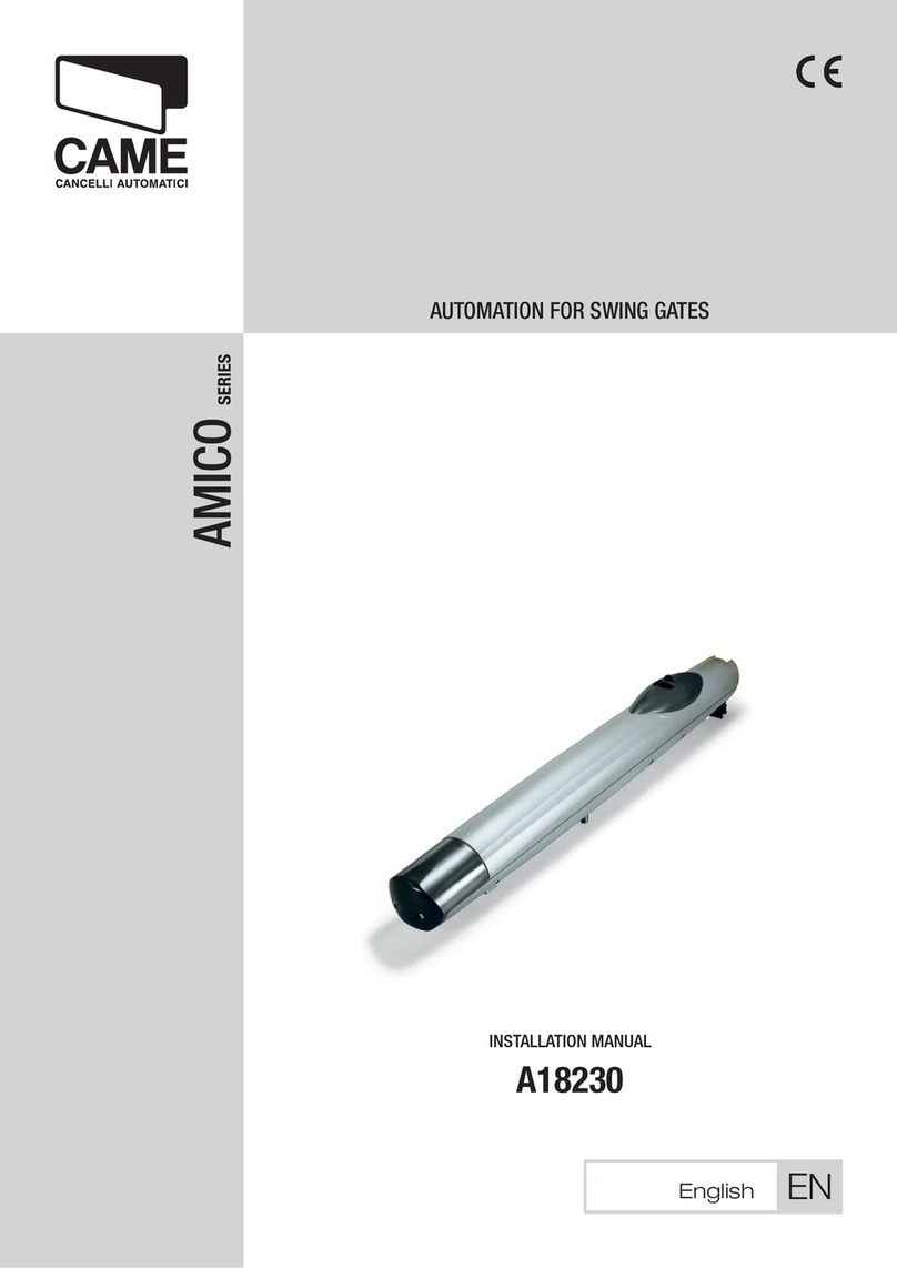
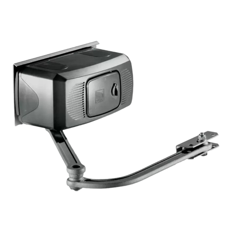
CAME FROGPLUS-S7 User manual

Other CAME Gate Opener manuals

CAME BXV04AGS User manual

CAME

CAME BXV04AGS User manual

CAME 806LA-0050 User manual

CAME

CAME 806LA-0050 User manual

CAME BK-221 User manual

CAME

CAME BK-221 User manual

CAME BKX12AGF User manual

CAME

CAME BKX12AGF User manual

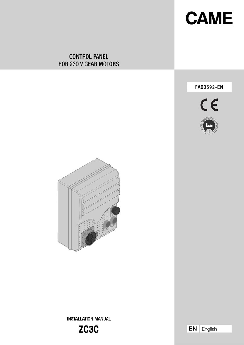
CAME ZC3C User manual

CAME

CAME ZC3C User manual

CAME FA40230CB User manual

CAME

CAME FA40230CB User manual

CAME TOP-864EE User manual

CAME

CAME TOP-864EE User manual

CAME BX-64B User manual

CAME

CAME BX-64B User manual

CAME FROG series User manual

CAME

CAME FROG series User manual

CAME DFW Series User manual

CAME

CAME DFW Series User manual

CAME CBX series User manual

CAME

CAME CBX series User manual

CAME OPS series User manual

CAME

CAME OPS series User manual

CAME FROG A24 User manual

CAME

CAME FROG A24 User manual

CAME BXV1000GF User manual

CAME

CAME BXV1000GF User manual

CAME ATS-P524 User manual

CAME

CAME ATS-P524 User manual

CAME Ferni Series User manual

CAME

CAME Ferni Series User manual

CAME BXV Rapid Series User manual

CAME

CAME BXV Rapid Series User manual

CAME 119RW45 User manual

CAME

CAME 119RW45 User manual

CAME FE40230 User manual

CAME

CAME FE40230 User manual

CAME ATI KIT User manual

CAME

CAME ATI KIT User manual

CAME VER10 User manual

CAME

CAME VER10 User manual

CAME FERNI User manual

CAME

CAME FERNI User manual

CAME BXV400GS User manual

CAME

CAME BXV400GS User manual

CAME F1024 User manual

CAME

CAME F1024 User manual

Popular Gate Opener manuals by other brands

Nortek Security & Control Mighty Mule HD272 installation manual

Nortek Security & Control

Nortek Security & Control Mighty Mule HD272 installation manual

tousek TURN 10 Installation and operating instructions

tousek

tousek TURN 10 Installation and operating instructions

SOMFY AXOVIA 220B RTS installation instructions

SOMFY

SOMFY AXOVIA 220B RTS installation instructions

Nice HySecurity CBOX1050 Installation and programming manual

Nice HySecurity

Nice HySecurity CBOX1050 Installation and programming manual

Aprimatic ONDA 500 installation instructions

Aprimatic

Aprimatic ONDA 500 installation instructions

Turnstiles FSW 900 manual

Turnstiles

Turnstiles FSW 900 manual

Erreka BUL BL33 Quick installation and programming guide

Erreka

Erreka BUL BL33 Quick installation and programming guide

Extel VERA quick guide

Extel

Extel VERA quick guide

Beninca R1-2 WBV quick start guide

Beninca

Beninca R1-2 WBV quick start guide

Erreka VULCAN D user manual

Erreka

Erreka VULCAN D user manual

Motorline professional FORT User& installer's manual

Motorline professional

Motorline professional FORT User& installer's manual

Beninca BOB5024 manual

Beninca

Beninca BOB5024 manual

AGA GATEMASTER 900 HD installation manual

AGA

AGA GATEMASTER 900 HD installation manual

Cardin BL Series manual

Cardin

Cardin BL Series manual

Westfalia 85 27 06 instruction manual

Westfalia

Westfalia 85 27 06 instruction manual

Riello Elettronica CARDIN ACE FAST Instruction handbook

Riello Elettronica

Riello Elettronica CARDIN ACE FAST Instruction handbook

Telcoma ARM Instruction handbook

Telcoma

Telcoma ARM Instruction handbook

Telcoma ACE Instruction handbook

Telcoma

Telcoma ACE Instruction handbook

manuals.online logo
manuals.online logoBrands
  • About & Mission
  • Contact us
  • Privacy Policy
  • Terms and Conditions

Copyright 2025 Manuals.Online. All Rights Reserved.

CAME.COM/UK
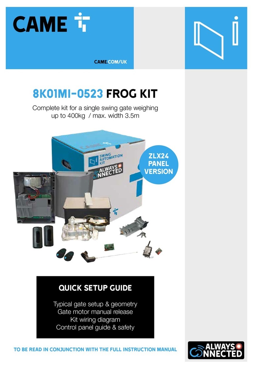
FROGPLUS-S7 kit
Complete kit for a single swing gate weighing
up to 550kg / max. width 7m
TO BE READ IN CONJUNCTION WITH THE FULL INSTRUCTION MANUAL
QUICK SETUP GUIDE
Typical gate setup & geometry
Gate motor manual release
Kit wiring diagram
Control panel guide & safety
CONTENTS
AF43S
Radio Frequency Card
FROG-PC
Foundation Box
frog-PM6
Motor
x2
FROGPLUS-S7: KIT CONTENTS
DIR10
Pair of Photocells
top-a433n
Tuned Antenna
topd4rks
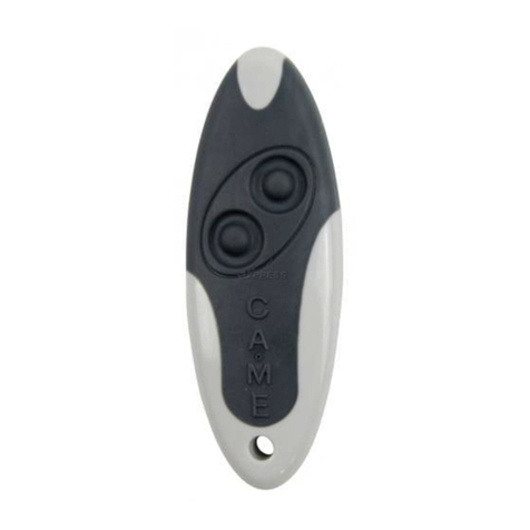
Rolling code Transmitter
ZM3EP
Control Panel
A4364
Release Device with
Lever Key
RGSM001S
Gateway Module
RSE
Connection Card
SIM
May be preinstalled in
RGSM001S
1Kit Contents
2Safety Instructions
3Typical Gate Setup
4Geometry
5Manual Release Instructions
6Wiring Diagram
7Pre-installed SIM Card
8Initial Power On
9Commissioning the RGSM
10 Commissioning via App
11 Commissioning via Panel
12 Safety Options
13 Replacing the SIM Card
14 Optional Accessories
2SAFETY INSTRUCTIONS
When correctly installed in compliance to installation instructions and adhering to all
current electrical, mechanical and manufacturer regulations, your automation system
will provide a high degree of safety and problem free operation.
Please take note of the following warnings that must be followed in order to
prevent accidents during your gate operation:
• Do not allow children to play near the gate.
• Keep all remote control operating devices out of the reach of children.
• Do not pass through the gate whilst in operation. Wait until they are fully open before passing through.
• Do not stop unnecessarily when passing through the gate.
• Keep feet away from the bottom of the gate during operation.
• Do not operate the gate by remote control unless they are in view.
• Do not attempt to block or interfere with the gate movement during operation.
• Under no circumstances should you attempt to modify the gate automation system.
• Ensure that your gate is serviced at 3 to 12 month intervals (dependent on number of openings) by your installation/
maintenance company.
• Report any signs of malfunction to your installation/maintenance company immediately.
• In the case of malfunction, isolate the power supply, release any additional locking mechanism, manually open the
gate (see manual release instruction booklet) and call your installation/maintenance company.
• If you are in any doubt regarding the operation of your gate, call your installation/maintenance company.
3 TYPICAL GATE SETUP
CONTROL PANEL
PHOTOCELLS
• The control panel should be mounted in an accessible position and not directly behind the gates, to avoid a
potential crushing hazard.
• Use cable glands to connect the devices to the control panel. One of these must be used exclusively for the
power supply cable.
• All holes should be sealed to avoid ingression and maintain the IP54 protection rating.
Only a competent service provider should open the enclosure
and adjust the settings.
• The photocells are used in pairs, one transmitter and one receiver.
• They should be installed between 500-600mm from the ground, facing each other.
• Power for the photocells is taken from the control panel 24v AC.
• The maximum range of the photocell should always be observed.
When the photocell beam is broken, the control panel can be programmed on how to react.
Please see ‘Safety’ section for more information.
1
7
8
8
9
2
5
34
6
10
OUTSIDE OF GATES
INSIDE OF GATES
1FROG Plus Motor with
Foundation Box
4Flashing Light (optional) 8Mechanical End Stop (not supplied)
5Selector Keypad (optional) 9Photocell column (optional accessory)
2Control Panel 6Photocells (on outside of gate posts) 10 Latch
3Reception Antenna 72nd set of Photocells (optional)
4 GEOMETRY
Preliminary checks
Tick
1. Check that the gate structure is sturdy enough, the hinges work efficiently and that there is
no friction between the fixed and moving parts
2. Check that the foundation box is correctly installed
3. Make sure that you have fitted opening and closing mechanical gate stops
4. Ensure that the gate corresponds with the motor limits
• Manually open the leaf.
• Position the gearmotor over the threaded pins
of the casing and fasten it.
• Lubricate the transmission lever.
• Fit the transmission lever as shown in the
drawings.
Page 99- Manual code: FA00597- ENFA00597-EN ver. 1105/2018 © CAME S.p.A. - The data and information provided in this manual are subject to change at any time without prior notice byCAME S.p.A.
Open the door to facilitate the placement of the gearmotor in the foundation case and its anchoring.
Secure the gearmotor using the nuts supplied.
M12 nut
UNI 5588
Fastening the gearmotor
Before fastening the gearmotors, fit the adjusting screws into the gearmotor drive arms, as shown in the drawing.
LEFT SIDE RIGHT SIDE
Page
10
10 - Manual code:
FA00597-EN
FA00597-EN ver.
1
105/2018 © CAME S.p.A. - The data and information provided in this manual are subject to change at any time without prior notice by CAME S.p.A.
Lubricate the transmission lever and fit it into the hole of the gearmotor arm and case lever.
Determining the end run points
During opening:
- Fully open the leafs (the maximum aperture is 110 °);
- loosen the screw until it makes contact with the body ;
- tighten the nut to lock the position of the screw.
During closing:
- close the leaves completely;
- loosen the screw until it makes contact with the transmission arm ;
- tighten the nut to lock the position of the screw.
Page
9
9- Manual code:
FA00597-EN
FA00597-EN ver.
1
105/2018 © CAME S.p.A. - The data and information provided in this manual are subject to change at any time without prior notice byCAME S.p.A.
Open the door to facilitate the placement of the gearmotor in the foundation case and its anchoring.
Secure the gearmotor using the nuts supplied.
M12 nut
UNI 5588
Fastening the gearmotor
Before fastening the gearmotors, fit the adjusting screws into the gearmotor drive arms, as shown in the drawing.
LEFT SIDE RIGHT SIDE
Page 1010 - Manual code: FA00597-ENFA00597-EN ver. 1105/2018 © CAME S.p.A. - The data and information provided in this manual are subject to change at any time without prior notice by CAME S.p.A.
Lubricate the transmission lever and fit it into the hole of the gearmotor arm and case lever.
Determining the end run points
During opening:
- Fully open the leafs (the maximum aperture is 110 °);
- loosen the screw until it makes contact with the body ;
- tighten the nut to lock the position of the screw.
During closing:
- close the leaves completely;
- loosen the screw until it makes contact with the transmission arm ;
- tighten the nut to lock the position of the screw.
gate geometry
• It is always advisable to install an electric lock, to
ensure reliable closure of the gate.
• The installation of an electric lock is mandatory with
gate leaves longer than 2.5 m
Gate leaf length (m) 5.5 4.5 3.5 2.5 1.5
Gate leaf weight (kg) 700 900 1100 1400 1800
LIMITS TO USE
Pillar
Leaf - closed
position
Hinge
94mm*
94mm
426mm
*It is critical that the distance between the pillar
and the centre of the hinge be AT LEAST 94mm
in order for the motor to operate correctly.
For installations with gates opening outwards please refer to the main manual
5 MANUAL RELEASE
To manually release the gates:
1. Lift tab.
2. Insert lever into the lock and turn 90 to
realease A1 .
3. The gate should should now be manually
released. With your other hand firmly open the
gate. Now fully open the gate carefully at the
same speed as the automatic operator A2 .
If the gate is heavy please seek assistance to
open/close it.
4. To re-engage, close the gate and turn the
key back to its original position. Attempt to
manually move the gate to ensure it is fully
engaged B.
5. Please note, it may be necessay to operate
the motor once power is restored to fully
engage the system. Please take care when
operating the system in this manner.
The FROG PLUS underground system is supplied with a lever release system 01 .
Basic Maintenance: Hints & Tips
• Lift manual release tabs & spray the locks on both
sides with suitable penetrating lubricant.
• Spray into the lock at the connection point (brass
part) with suitable penetrating lubricant.
• Lubricate gate hinges.
• Manually release the gates at least once per month.
ALWAYS isolate the power supply as
instructed by your installer (even in a
power cut).
Release any additional locking
device fitted to the gate (eg. electric
lock etc).
a
B
01
6 wiring diagram
4
3
2
1
+ -E 10 11 ES TS 1 2 23 3P CX CY CZ4 5 7 GND FA1 FC1 FA2 FC2S1 B1 B2+ -EEYX E3WVU
L N
4
3
2
1
ZM3EP
Control Panel
AF43S
Plug-in
RSE
Set RSE jumper
to OFF
TOP-A433N
Antenna
Cable/length
RG58
Max. 5m
DIR
Photocells
Cable/length
RX 4 Core 0.5mm Flex
TX 4 Core 0.5mm Flex
1m - 30m
+ -
10 2 TX C NC TX 2
RX TX
RGSM001S
Gateway Module
Cable/length
Max 3m power
10 2 A B GND
Mains Supply
230 V AC
Cable/length
1m - 20m = 3 Core 1.5mm
20m - 30m = 3 Core 2.5mm
The Earth cable should
be connected to the
motor chassis.
FROG-PM6
Gate motor
npower Cable/length
1m - 20m = 3 Core 1.5mm
20m - 30m = 3 Core 2.5mm
nencoder cable/length
+ / E / - Cable
Belden 8723 or equivalent
Max 30m
TITLE7pre-installed sim card
The pre-installed SIM card is an IOT/M2M multi SIM complete with 480MB data allowance and 3 year life term.
Under average usage of 3-4 gate manoeuvres per day, the data should last approximately 3 years.
In case you use up the 480MB data volume before the end of the 3-year term, you can easily add another 480MB data
volume by making a top-up, details of which can be found here:
www.cameconnect.co.uk/gsmmodule
Due to situations outside of our control, CAME cannot guarantee signal strength or availability and therefore will not be
held liable for lack of service.
came automation
internet
came cloud
setup app
for the installer
GET IT ON
App Store
GET IT ON
automation app
for the end user
GET IT ON
App Store
GET IT ON
System Frequency Approx. Movements Est. SIM Life Based on Usage
Occasional Usage Approx. 5 gate manoeuvres per
week
4-7 Years*
Average Usage** Approx. 3-4 gate manoeuvres
per day
3-4 Years
High Usage Approx. 5+ gate manoeuvres per
day, multiple scenarios running
1-3 Years
* SIM will expire after 3-4 years. (CAME guarantees 3 years with some tolerance for shelf life consideration)
** We anticipate SIM provided will have sufficient data for Average Usage (as shown above) lasting approx. 3 years
TITLE
7pre-installed sim card
The pre-installed SIM card is an IOT/M2M multi SIM complete with 480MB data allowance and 3 year life term.
Under average usage of 3-4 gate manoeuvres per day, the data should last approximately 3 years.
In case you use up the 480MB data volume before the end of the 3-year term, you can easily add another 480MB data
volume by making a top-up, details of which can be found here:
www.cameconnect.co.uk/gsmmodule
Due to situations outside of our control, CAME cannot guarantee signal strength or availability and therefore will not be
held liable for lack of service.
came automation
internet
came cloud
setup app
for the installer
GET IT ON
App Store
GET IT ON
automation app
for the end user
GET IT ON
App Store
GET IT ON
System Frequency Approx. Movements Est. SIM Life Based on Usage
Occasional Usage Approx. 5 gate manoeuvres per
week
4-7 Years*
Average Usage** Approx. 3-4 gate manoeuvres
per day
3-4 Years
High Usage Approx. 5+ gate manoeuvres per
day, multiple scenarios running
1-3 Years
* SIM will expire after 3-4 years. (CAME guarantees 3 years with some tolerance for shelf life consideration)
** We anticipate SIM provided will have sufficient data for Average Usage (as shown above) lasting approx. 3 years
8initial power ON
OUT1OUT2
Keycode
123456789ABCDE F
MATR
54051 6
300mAE GSM – 900 33dBm
DCS – 1800 30dBm
869.5MHz 14dBm
24V
CONNECT
123 4
GND
A
N
T
10+
2
COM
IN2
COM
IN1
B
A
–
1A 30V
RGSM001S
1 2
1GSM LED (Blue)
After a few seconds the LED will flash 1x/sec indicating the RGSM001S is registered on a GSM network.
2POWER LED (Green)
The LED will flash 5x/sec indicating the RGSM001S is not yet configured on the Connect platform
Power on the control board.
The display will read
26V
0V
17V
0
230V 26V
0V
17V
0
230V
M1 N1 E1 E2M2 11N2 + -E+ -E 10 TS E ES 1 2 3 3P 5 7
BGND GNDS1A B1 B2
CX 2CY CZ4 FA1 FC1 FC2FA2
L N
WWW.CAME.COM
ZM3E
to check motor direction using control panel
CAUTION, Ensure the gate movement area is clear of all obstructions
Check the motor direction TEST MOT
Press and hold =M2
The gate should open, if not reverse the motor cables (Connections M2, N2)
Leave the gate leaf in the halfway position.
Installer Tip
If the RGSM001S is located
in a concealed area and a low
GSM signal observed a 2m
extension cable and bracket is
available to purchase.
This then allows the aerial to
be located in a more suitable
position. Part No:
806SA-0050
TITLE9 commissioning the rgsm
3.1 Open the App and log in
using your technician details
as registered.
3.2 Select “CAME Connect
connection”.
3.3 Select “Site
management”.
3.4 Fill in a site “Name” and
“Description” and then press
“Add”.
2.1 Select “Register as
technician”.
2.2 Fill in your details and
then “Confirm”.You will
receive an email containing
your log in information
and request to confirm the
account. Should the email not
arrive, please check your junk
folder.
download the
connect setup app
adding the rgsm gateway
to your technician account
technician
connect setup app
1
3
2
If you have an existing account, please move to step 3.
Important!
The installation must be carried out
by skilled and qualified personnel
Mr Wilson, Sills Road, DE74 2US
1.1
GET IT ON
App Store
GET IT ON
Installer Tip
The Name and Description entered
here, can be used to identify the
site location.
Name: Mr Wilson, Sills Rd, DE74 2US
Description: Mr Wilson, Sills Rd,
DE74 2US
This shows in the Installers
Setup App, under the site
management list.