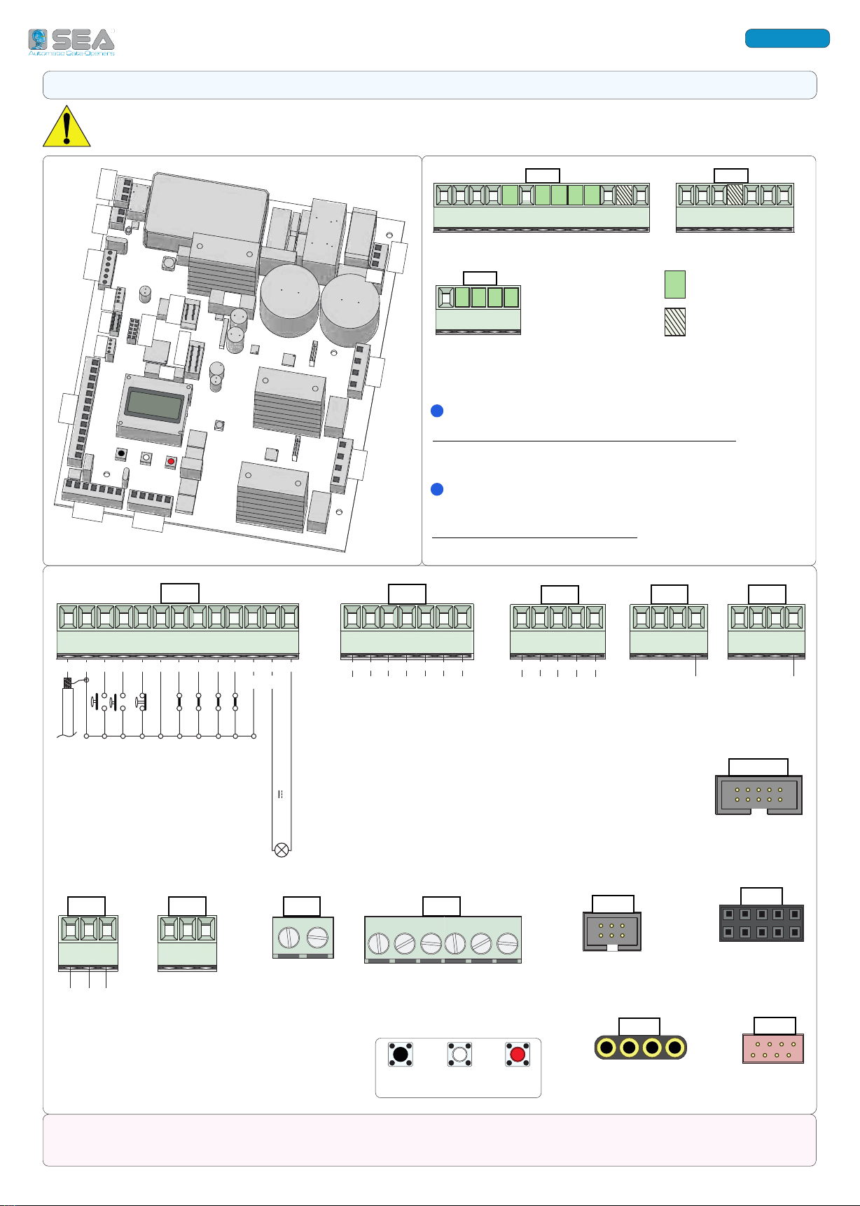
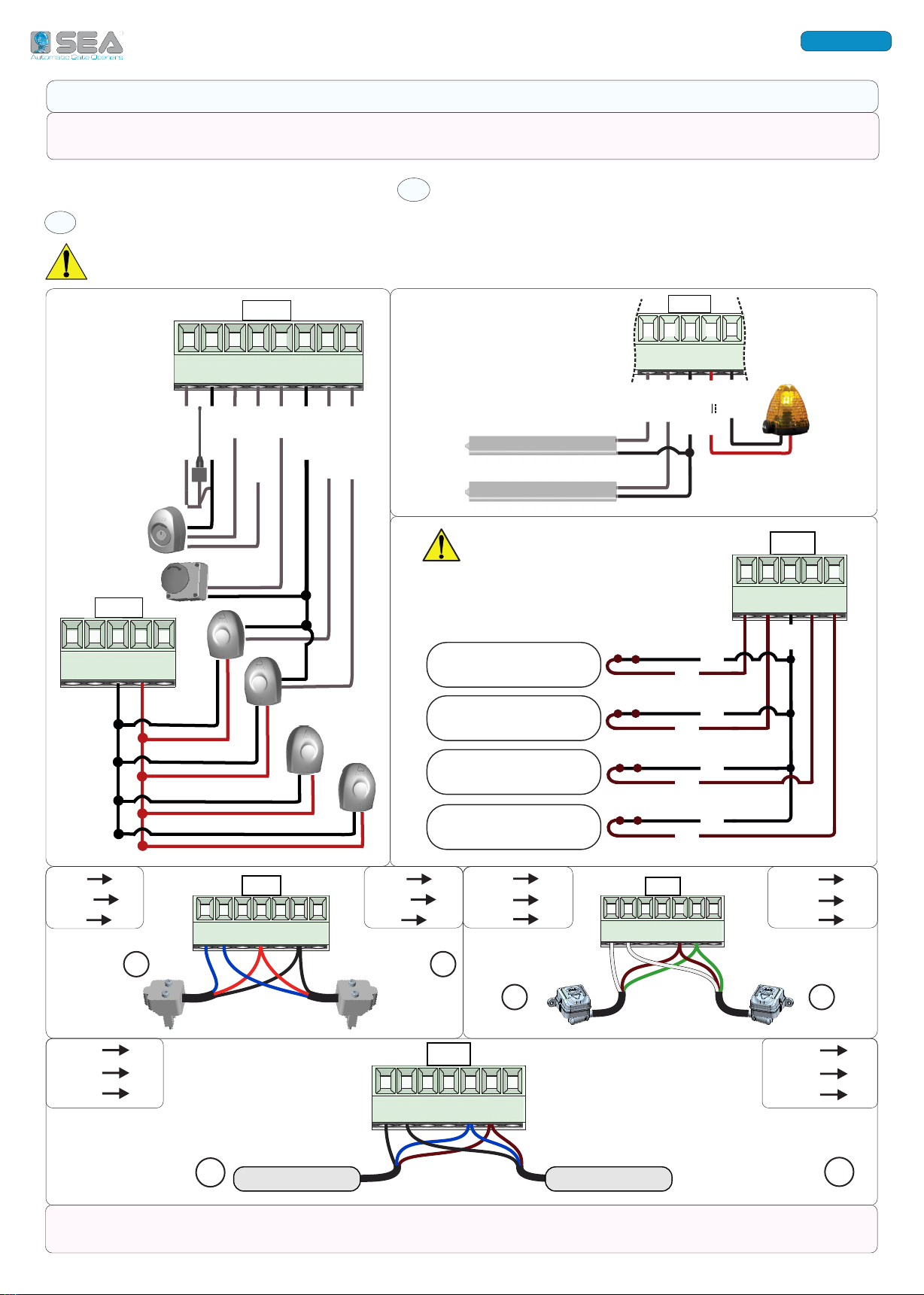
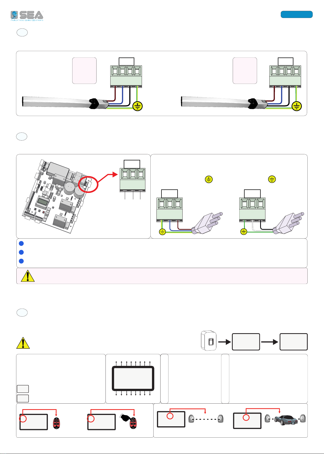
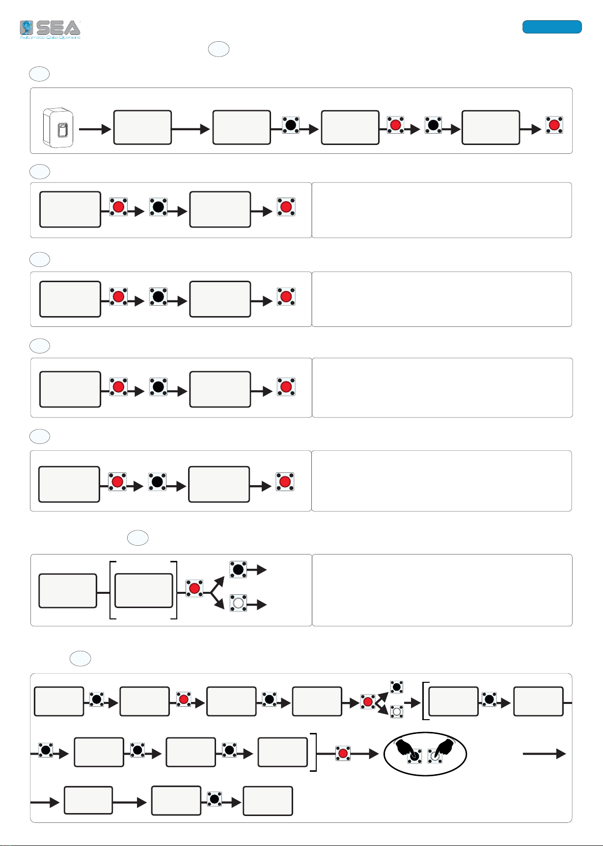
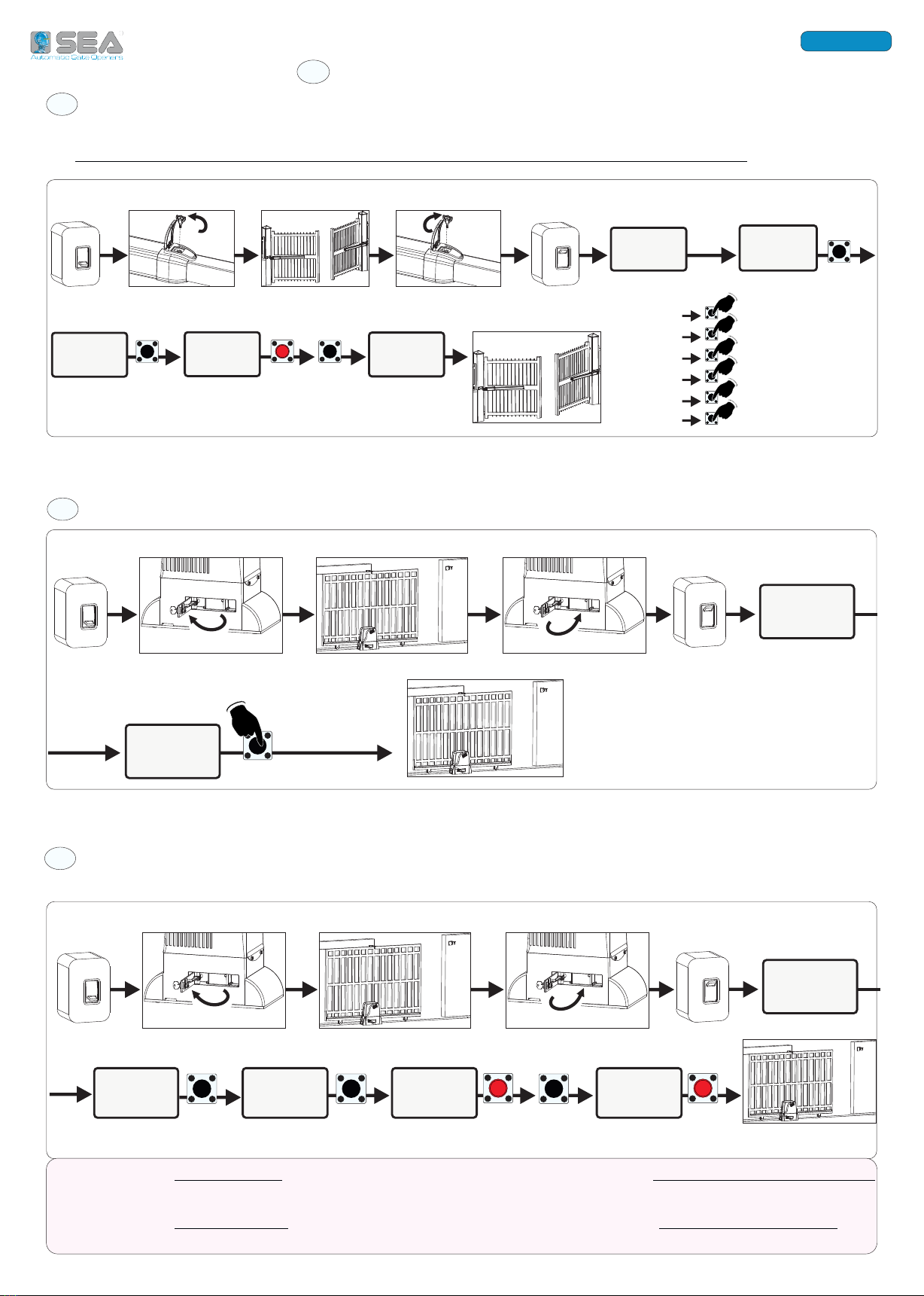
SEA GATE 2 DG INVERTER User manual

IT - EN - FR
QUICK START
International registered trademark n. 804888
67412241 REV. 00 - 05/2023
SEA S.p.A.
Zona Industriale Sant’Atto - 64100 - Teramo - ITALY
Telephone: + 39 0 861 588341
www.seateam.com
GATE 2 DG INVERTER
INVERTER CONTROL UNIT
TO MANAGE
ONE or TWO OPERATORS
(230V/110V)
FULL MANUAL
(Rev. 01)
&
SAFETY
INFORMATION

International registered trademark n. 804888
Italiano
ENGLISH
1 - COMPONENTS
22
2 - QUICK START SEQUENCE:
23
23
WIRINGS
A
23
A1
BBASIC MENU SETTINGS
« »
CMOTORS OPERATION TEST (MENU 192 193)
WORKING TIMES LEARNING
E
GATE 2 INVERTER control unit requires the working times learning procedure!
it is not possible to start the operator correctly without first programming the control unit!
25
25
3 - TMENU TABLE
DACTIVATION OF ENCODER POTENTIOMETER (IF INSTALLED)
25
«»
A2
A3
A4
24
24
24
25
25
25
25
25
B1
B2
B3
B4
B5
26
26
26
27
27
E1
E2
E3
E4
E5
28
30
26
INDEX
- 1
- 6
- 4
- 3
- 7
SEA

International registered trademark n. 804888
Italiano
ENGLISH
14 15 16 17 18 19 20
1 - COMPONENTS
UP DOWN OK
JOLLY
CNA
CNP
OPEN
(Firmware update)
CNS
CN1
ANT COM START STPD STOP COM PH1 PH2 EDGE1 EDGE2 COM AUX FL(-)
98
7
6
5
4
3
2
110 13
12
11
24V DC
TO RESTORE THE EXCLUDED INPUTS , ENTER THE
«INPUTS MANAGEMENT» MENU (SEE PAGE 24)
NO NEED TO SET UP THE UNIT AGAIN!
14 15 16 17 18 19 20
CN2
CN2
CN3
CN3 CN4
GP1 GP2 GP3 24V +PG COM COMIS
31 32 33 34 35
31 32 33 34 35
COM LSO1 LSC1 LSO2 LSC2
AUTOMATIC RECOGNITION OF THE N.C. INPUTS NOT IN USE
NO JUMPERS ARE REQUIRED ON THE N.C. CONTACTS!
Start
Stop
Antenna
Lamp 3W max
-
+
CN1
ANT COM START STPD STOP COM PH1 PH2 EDGE1 EDGE2 COM AUX FL(-)
98
7
6
5
4
3
2
110 13
12
11
*24V - max. 1A
(+) Position Gate
Common
Common
accessories
COM LSO1 LSC1 LSO2 LSC2
W2 V2 U2 PE
Ground
Ground
CN5
Ground
W1 V1 U1 PE
CN7
COM NO NC
CN6
PE N L
Neutral
Line
EXP
A1 COM B1 12V A2 B2
CN9
CN8
12V
ELECTRIC
LOCK RS 485 SERIAL
CONNECTOR
Common
Common
Photocell 1
Common
*AUX programmable
24Vdc 1A max.
Photocell 2
Partial START
Safety edge 2
N.C. CONTACTS
Safety edge 1
Programmable input 1
Programmable input 2
Programmable input 3
Common
Opening limit switch 1
Closing limit switch 1
Opening limit switch 2
Closing limit switch 2
JOLLY 3
SEACLOUD
RF RECEIVER
CONNECTOR
RF FIX RECEIVER
CONNECTOR
PROGRAMMING BUTTONS
RELAY
DRY CONTACT
EXTERNAL
MODULE
CONNECTOR
* All the 24V inputs support a maximum load of 1A - referred to the sum of the loads of all 24V accessories
connected, including the absorption of the receiver on board (30 mA)
BLACK WHITE RED
Keep the power cables separate from the command cables - always run cables in separate sheaths to prevent interferences!
Make all the wirings when the control unit is not powered!
CN7
CN8
CN9
CNS
CNA
CNS
CN1
CN4 CN5 CN6
CN2 CN3
JOLLY EXP
PROG
F2
F1
BT

International registered trademark n. 804888
Italiano
ENGLISH
WIRINGS
A
A1
2 - QUICK START SEQUENCE
F A - B - C - D - E
F , !
WIRING OF THE MAIN ACCESSORIES ON THE CONTROL UNIT
Make all wirings when the unit is not powered!
Do not jumper the N.C. inputs not in use!
14 15 16 17 18 19 20
CN2
CN1
13
12
11
10
9
14 15 16 17 18 19 20
CN2
ENCODER M1 ENCODER M2
14 15 16 17 18 19 20
CN2
M1 M2
SAFETY EDGE 1
SAFETY EDGE 2
24V AUX
Edge 1
Edge 2
Common
Lamp
FL(-)
8
7
6
5
4
3
2
1
CN1
TX1
TX2
24Vaux
CN1
RX1
RX2
Start
Stop
Antenna
13
12
11
910
Common
Common
Common
Photocell 1
Photocell 2
Partial Start
CN3
31 32 33 34 35
N.C.
N.C.
N.C.
N.C.
32
31
33
31
34
31
35
31
Com
IN CASE OF SINGLE LEAF, ONLY WIRE
THE MOTOR 1 LIMIT SWITCHES;
DO NOT JUMPER MOTOR 2 LIMIT SWITCHES!
OPENING LIMIT SWITCH
MOTOR 1
CLOSING LIMIT SWITCH
MOTOR 1
OPENING LIMIT SWITCH
MOTOR 2
CLOSING LIMIT SWITCH
MOTOR 2
«RT» ABSOLUTE
ENCODER «RT» ABSOLUTE
ENCODER
POTENTIOMETER M1 POTENTIOMETER M2
For the wiring of further accessories, for encoder/potentiometer adjustments and for more details on
accessories settings, use the full technical manual!
BLUE 14
BLACK 17
RED 19
BLUE 15
BLACK 17
RED 19
WHITE 14
BROWN 18
GREEN 19
BLACK 14
BLUE 18
BROWN 19
BLACK 15
BLUE 18
BROWN 19
WHITE 15
BROWN 18
GREEN 19

International registered trademark n. 804888
Italiano
ENGLISH
OPERATORS WIRINGS
Wirings of one or two operators to the control unit
A2
Control unit wiring to the main power supply
A3
A4
POWER
00111110
11110000
03.00
ON
CN5
W1 V1 U1 PE
= BROWN
= BLUE
= BLACK
= YELLOW/GREEN
W1
V1
U1
PE
MOTOR 1 (230V)
= BROWN
= BLUE
= BLACK
= YELLOW/GREEN
W2
V2
U2
PE
MOTOR 2 (230V) CN4
W2 V2 U2 PE
M2 (120V)
= BLACK
= WHITE
= RED
= GREEN
W2
V2
U2
PE
M1 (120V)
= BLACK
= WHITE
= RED
= GREEN
W1
V1
U1
PE
(EXAMPLE)(EXAMPLE)
POWER SUPPLY
= BROWN
= BLUE
= YELLOW/GREEN
L
N
PE
(230V ± 5%)~
CN6
PE N L
Ground
Neutral
Line
CN7
CN8
CN9
CNS
CNA
CNS
CN1
CN4 CN5 CN6
CN2 CN3
JOLLYEXP
PROG
F2
F1
BT
CN6
PE N L
= BLACK
= WHITE
= GREEN
L
N
PE
(120V ± 5%)~
CN6
PE N L
F , !
Fuse 16AT delayed on 230V~ and 115V~ power supply
In case of unstable power supply, the use of an external UPS of min. 800VA is recommended
Use a 10A differential switch to protect the power supply system
CHECKING OF THE WIRED ACCESSORIES BY THE «INPUTS STATUS» MENU
Turn on the control unit and check for the correct status of the inputs
S P S N.O. (0)
A N.C. (1)
5
SECONDS
EXAMPLE
SOFTWARE
REVISION INPUTS
STATUS
11110000 11110000 11110000 11110000
00111110
1 2 3 4 5 6 7 8 1
2
3
4
5
6
7
8
9
10
11
12
13
14
15
16
Every input corresponds to a
position on the display, according
to the diagram aside;
Every input can be:
00111110
START
(N.O.)
00111110 00101110
9 10 11 12 13 14 15 16
0
1
N.O. - NORMALLY OPEN
N.C. - NORMALLY CLOSED
START (**)
PARTIAL START
STOP
PHOTOCELL 1
PHOTOCELL 2
SAFETY EDGE 1
SAFETY EDGE 2
NOT IN USE
MOTOR 1 OPENING LIMIT SWITCH
MOTOR 1 CLOSING LIMIT SWITCH
MOTOR 2 OPENING LIMIT SWITCH
MOTOR 2 CLOSING LIMIT SWITCH
NOT IN USE
GP1
GP2
GP3
PHOTOCELL 1
(N.O.)
PHOTOCELL 1
(N.C.)
START
(N.C.)
10111110
11110000

International registered trademark n. 804888
Italiano
ENGLISH
B
B1
B2
B3
B4
B5
4
GATES
NUMBER
7
TIMER TO
CLOSE
CMOTORS OPERATION TEST (MENU 192 193)
BASIC MENU SETTINGS
- 1
- 4
- 3
- 6
- 7
SOFTWARE
REVISION INPUT
STATUS
ON
POWER ON
UP OK UP OK
00111110
03.00
5
SECONDS
1
LANGUAGE
ENGLISH
EXAMPLE
ENCODER POTENTIOMETER ACTIVATION (ONLY IF INSTALLED)
D
11110000
UP OK OK
UP
32
ENCODER
DOWN
UP
UP DOWN
UP
ON
UPUP UP
POSITION
GATE
RT RS 485
OFF
OK
03.00
11110000
00111110
5 SEC.
UP
1
LANGUAGE
1
LANGUAGE
16
SPECIAL
MENU
SPECIAL MENU
17
OPENING
SPEED
CONFIRM THE
TYPE IN USE HOLD PRESSED
5 SECONDS
TO EXIT THE
SPECIAL MENU
SOFTWARE REVISION INPUTS STATUS
OK UP OK
1-HYDRAULIC
When a type is set, the parameters of the special
menu automatically set to the useful values for that
type!
OK UP OK
Choose the number of operators to manage
2
OK UP OK
6
LOGIC
AUTOMATIC
Select the desired operating logic. If a pause time
other than zero is set in the following menu, the
automatic reclosing will always be active.
OK UP OK
10
SECONDS
Set a pause time other than zero to enable the
automatic reclosing. If set to «0» the automatic
reclosing will be disabled (i.e. in this case the «semi-
automatic» logic will be in use)
3
MOTOR
EXAMPLE
EXAMPLE
EXAMPLE
EXAMPLE
192
MOVE
GATE 1
7
TIMER TO
CLOSE
UP
DOWN
OK
193
MOVE
GATE 2
If the gate opens by pressing UP and if the gate
closes by pressing DOWN, then the operators
run correctly, otherwise swap the motor cables.
In case of 2 operators, test the second one in the
same way via menu 193

International registered trademark n. 804888
Italiano
ENGLISH
E
E1
E2
E3
a
a
a
WORKING TIMES LEARNING
WORKING TIMES LEARNING THROUGH MANUAL PULSES ON THE POINTS OF STOP
ie: double hydraulic swing operator)
When the learning cycle starts, press UP on the stop points of each motor (M1 - M2)
}
UP
03.00
11110000
00111110
OK UP
ON
M1 M2
OFF ON
POWER
OFF
POWER
ON
UP
UP
UP
UP
UP
UP
UP
MANUAL
PULSES
ON STOP
POINTS
UNLOCK LOCK
LEAVES ON HALFWAY
(EXAMPLE)(EXAMPLE)(EXAMPLE)
SOFTWARE
REVISION
INPUTS
STATUS
5
SECONDS
1
LANGUAGE
9
PROGRAMMING
THE LEARNING CYCLE STARTS:
M2 CLOSES
M1 CLOSES
M1 OPENS
M2 OPENS
M2 CLOSES
M1 CLOSES
(EXAMPLE)
SEA SLIDING OPERATORS
OFF ON
POWER
OFF
POWER
ON
11110000
00111110
UP
03.00
(EXAMPLE)
(EXAMPLE)
SOFTWARE
REVISION
LEAF ON HALFWAY
UNLOCK LOCK
HOLD
PRESSED
THE LEARNING CYCLE STARTS:
CLOSE - OPEN - CLOSE
5
SECONDS
5 SECONDS
INPUTS
STATUS
LIMIT SWITCH
The limit switches are automatically detected
11110000
00111110
5
SEC.
UP UP OK UP
ON
OK
OFF ON
POWER
OFF
POWER
ON
03.00
(EXAMPLE)
(EXAMPLE)
SOFTWARE
REVISION
LEAF ON HALFWAY
UNLOCK LOCK
INPUTS STATUS
1
LANGUAGE
PROGRAMMING
9
THE LEARNING CYCLE STARTS: CLOSE - OPEN - CLOSE
If the motor starts closing, reaches the limit switch lever and stops, then swap the limit switch cables
and repeat the procedure;
If the motor starts opening, reaches the limit switch lever and stops, then swap the motor cables and
repeat the procedure;
(for operators without limit switch, without encoder and without potentiometer -

International registered trademark n. 804888
Italiano
ENGLISH
E4
E5
POTENTIOMETER or ENCODER «RT»: the learning cycle always includes the slowdown cycle!
a
a
a
a
a
UP
UP
ON
ON
5
5
* procedure valid only for swing operators with ENCODER «RT»
M1 OPENS WITH SLOWDOWN
M2 OPENS WITH SLOWDOWN
M2 CLOSES WITH SLOWDOWN
M1 CLOSES WITH SLOWDOWN
STANDARD ENCODER
POTENTIOMETER OR ENCODER «RT»*
UP
UNLOCK LOCK
03.00
11110000
00111110
ON
M1 M2
OFF ON
POWER
OFF
POWER
ON
UP
UP
OK
LEAVES ON HALFWAY
(EXAMPLE)(EXAMPLE)(EXAMPLE)
(EXAMPLE)
SOFTWARE
REVISION
INPUTS
STATUS
5
SECONDS
1
LANGUAGE
9
PROGRAMMING
THE LEARNING CYCLE STARTS:
M2 CLOSES
M1 CLOSES
M1 OPENS
M2 OPENS
M2 CLOSES
M1 CLOSES
If the learning cycle starts in opening, reverse the motors on menu 5 and repeat the procedure
SINGLE MOTOR or BARRIER: (always starting with the motor or beam halfway) - the learning cycle is: CLOSE - OPEN - CLOSE
REVERSE
MOTOR
REVERSE
MOTOR
UP
UNLOCK LOCK
03.00
11110000
00111110
ON
M1 M2
OFF ON
POWER
OFF
POWER
ON
UP
UP
OK
LEAVES ON HALFWAY
(EXAMPLE)(EXAMPLE)(EXAMPLE)
(EXAMPLE)
SOFTWARE
REVISION
INPUTS
STATUS
5
SECONDS
1
LANGUAGE
9
PROGRAMMING
THE LEARNING CYCLE STARTS:
M2 CLOSES
M1 CLOSES
M1 OPENS
M2 OPENS
M2 CLOSES
M1 CLOSES
SINGLE MOTOR or BARRIER: (always starting with the motor or beam halfway) - the learning cycle is: CLOSE - OPEN - CLOSE
If the learning cycle starts in opening, reverse the motors on menu 5 and repeat the procedure

SET DESCRIPTION DEFAULT NOTE
Italiano
Italian
English
English
Français
French
Español
Spanish
Dutch
Dutch
Start
Start
Partial opening
Partial opening
External module External module
Stop
Stop
Relay To enable the Relay for 3 seconds
Bistable Stop
Pressed once, it stops the gate.
Pressed twice, it reactivates the START input
Latch opening
One impulse opens and keep open.
A second impulse restore the movement
Latch closing
One impulse closes and keep closed.
A second impulse restore the movement
Unlock
To store a command for unlocking the electric brake
Delete a transmitter
To delete a single transmitter (TX)
Move to EEP
To transfer the transmitters stored on the control unit to
the external EEPROM (MEM), if connected
Clear memory
To delete the full transmitters memory on the receiver
End
To exit the menu "transmitters"
1- Hydraulic
Hydraulic operators - Series I (INVERTER)
2- Sliding
Sliding operators - Series I (INVERTER)
3- Reversible Sliding
Reversible sliding operators - Series I (INVERTER)
4- Mechanic Swing
Electromechanic swing operators - Series I (INVERTER)
7- Barrier Barriers - Series I (INVERTER)
10- JOINT Hydraulic operator - Series I (INVERTER)
4
GATES NUMBER From 1 to 2 To set the number of motors to be managed 1
On
To reverse the opening with the closing and vice-versa
(both motors and limit-switches are reversed)
Off Off
Automatic
Automatic logic - automatic reclosing enabled
Open-stop-close-stop-open
Step by step type 1
Open-stop-close-open
Step by step type 2
2 button
Two buttons
Safety
Safety
Dead man
Dead man
GATE 2 INVERTER MENU FUNCTIONS TABLE
MENU
1
LANGUAGE
English
5
REVERSE MOTOR
Off
6
LOGIC
Auto-
matic
2
TRANSMITTERS
Start
Partial
Opening
3
MOTOR
Mechanic

SET DESCRIPTION DEFAULT NOTE
Off
Semi-automatic logic enabled
(a START command opens and another START closes the
gate - automatic reclosing disabled)
1 240
To set a pause time (from 1 second to 4 minutes) before
the automatic reclosing
Off
The Start command is not accepted during pause
On
The Start command is accepted during pause
9
PROGRAMMING Off On To start the working times learning Off
10
TEST START Off On
To give a Start command for testing the automation
(It can be used only on units already programmed!)
Off
11 LEAF LENGTH
2m - 3m - 4m - 5m - 6m
This menu will be shown only if the option
10-JOINT is set in the menu 3-MOTORS.It allows to set
the leaf length (values in meters)
- - - -
14
RESET
192
MOVE GATE 1 *
- - - -
193
MOVE GATE 1 *
- - - -
15
END
16
SPECIAL MENU
MENU
7
TIMER TO CLOSE
Off
8
START IN PAUSE
Off
A count-down of 5 seconds will start by holding the UP button; at its end "INIT" will appear on the
display as confirmation of the control board reset
Allows the movement of the gate in a temporary "dead man" mode
(for example to test the correct running of the motor)
HOLD UP PRESSED = THE GATE OPENS
HOLD DOWN PRESSED = THE GATE CLOSES
Allows the movement of the gate in a temporary "dead man" mode
(for example to test the correct running of the motor)
HOLD UP PRESSED = THE GATE OPENS
HOLD DOWN PRESSED = THE GATE CLOSES
* The command is accepted only at the end of the cycle or after a STOP command; it is not accepted during the cycle and
during the pause
Press OK to return to the display of the firmware version
and to the one of inputs state
Press OK to enter the special menu

SET DESCRIPTION DEFAULT NOTE
17 OPENING SPEED 1 10 100 Speed in opening Motor 1 80
18 CLOSING SPEED 1 10 100 Speed in closing Motor 1 80
19 OPENING SPEED 2 10 100 Speed in opening Motor 2 80
20 CLOSING SPEED 2 10 100 Speed in closing Motor 2 80
21
SLOWDOWN SPEED IN
OPENING 1
From 10% to 60%
of the maximum speed
slowdown speed in opening Motor 1 30
22
SLOWDOWN SPEED IN
CLOSING 1
From 10% to 60%
of the maximum speed
slowdown speed in closing Motor 1 30
23
SLOWDOWN SPEED IN
OPENING 2
From 10% to 60%
of the maximum speed
slowdown speed in opening Motor 2 30
24
SLOWDOWN SPEED IN
CLOSING 2
From 10% to 60%
of the maximum speed
slowdown speed in closing Motor 2 30
25 LEARNING SPEED 10% 100 %
To adjust the working times learning speed. This
parameter can change according to the motor type set
50
26
LEAF DELAY IN OPENING Off 6 Setting from OFF to 6 seconds 1,5
27
LEAF DELAY IN CLOSING Off 20 Setting from OFF to 20 seconds 2,5
28
OPENING TORQ 1 30% 100%
Motor 1 opening torque:
by increasing the torque, more strength will be required
to execute the inversion in case of obstacle.
with hydraulic motors the torque will be on 100%
100
29
CLOSING TORQ 1 30% 100%
Motor 1 closing torque:
by increasing the torque, more strength will be required
to execute the inversion in case of obstacle.
with hydraulic motors the torque will be on 100%
100
30
OPENING TORQ 2 30% 100%
Motor 2 opening torque:
by increasing the torque, more strength will be required
to execute the inversion in case of obstacle.
with hydraulic motors the torque will be on 100%
100
31
CLOSING TORQ 2 30% 100%
Motor 2 closing torque:
by increasing the torque, more strength will be required
to execute the inversion in case of obstacle.
with hydraulic motors the torque will be on 100%
100
32
ENCODER
On
(only if connected via LSE
management unit)
ON = Encoder enabled
OFF = Encoder disabled
(when OFF, the working times learnt are only shown)
Off
47 ENCODER PAR. M1 xxx.
48 ENCODER TOT. M1 xxx.
49 ENCODER PAR. M2 xxx.
50 ENCODER TOT. M2 xxx.
SPECIAL MENU
PRESS AT THE SAME TIME FOR 5 SECONDS TO ENTER OR TO EXIT THE SPECIAL MENU
SPECIAL MENU
Impulses read by Encoder during operation (Motor 1)
Impulses stored during programming (Motor 1)
NOTE: The range of values that can be set in all the TORQUE menus may vary according to the operator model
Impulses read by Encoder during operation (Motor 2)
Impulses stored during programming (Motor 2)
NOTE: The range of values that can be set in all the SPEED menus may vary according to the operator model

SET DESCRIPTION DEFAULT NOTE
Position Gate To enable the reading of the potentiometer
RT To enable the reading of the Absolute Encoder
RS 485 To enable the reading of the "RS485" Absolute Encoder
51 I.PAR.M1 *- - - - - - - -
52 I.AP.M1
From the value learned
to ± 100 pulses
53 I.CH.M1
From the value learned
to ± 100 pulses
54 I.PAR.M2 *- - - - - - - -
55 I.AP.M2
From the value learned
to ± 100 pulses
56 I.CH.M2
From the value learned
to ± 100 pulses
32
ENCODER Off
ON = Encoder enabled
OFF = Encoder disabled
(when OFF, the working times learnt are only shown)
Off
65 OPENING TIME M1 xxx.s
66 CLOSING TIME M1 xxx.s
67 OPENING TIME M2 xxx.s
68 CLOSING TIME M2 xxx.s
10% (Fast intervention)
99% (Slow intervention)
To adjust the Encoder or Potentiometer intervention time
on Motor 1 in opening
Off (Intervention excluded) Disabled
10% (Fast intervention)
99% (Slow intervention)
To adjust the Encoder or Potentiometer intervention time
on Motor 1 in closing
Off (Intervention excluded) Disabled
10% (Fast intervention)
99% (Slow intervention)
To adjust the Encoder or Potentiometer intervention time
on Motor 2 in opening
Off (Intervention excluded) Disabled
10% (Fast intervention)
99% (Slow intervention)
To adjust the Encoder or Potentiometer intervention time
on Motor 2 in closing
Off (Intervention excluded) Disabled
10% (Fast intervention)
99% (Slow intervention)
To adjust the sensitivity in slowdown
Function available only on electro-mechanic operators
Off
With potentiometer
To set the inversion time in slow-down from 0to 5
seconds (= 99%) - available only if the potentiometer or
the RT absolute encoder have been wired and enabled
30%
(= 1,5s)
To show the current position of the potentiometer on the leaf moved
by Motor 2. This parameter is useful to see if the potentiometer is
correctly read
To show the impulses stored by the control unit when the leaf moved
by Motor 2 is fully open
To show the impulses stored by the control unit when the leaf moved
by Motor 2 is fully close
* While the partial impulses are displayed, it is possible to OPEN (by pressing UP) or CLOSE (by pressing DOWN) the operator
to verify the correct reading of the potentiometer
To show the current position of the potentiometer on the leaf moved
by Motor 1. This parameter is useful to see if the potentiometer is
correctly read
To show the impulses stored by the control unit when the leaf moved
by Motor 1 is fully open
To show the impulses stored by the control unit when the leaf moved
by Motor 1 is fully close
34
CLOSING SENSITIVITY
MOTOR 1
Off
35
OPENING SENSITIVITY
MOTOR 2
Off
To display the learnt value during the working times self learning, in
opening and closing (Motor 1) . With UP or DOWN it is possible to
increase or reduce the working times
To display the learnt value during the working times self learning, in
opening and closing (Motor 2) . With UP or DOWN it is possible to
increase or reduce the working times
33
OPENING SENSITIVITY
MOTOR 1
Off
36
CLOSING SENSITIVITY
MOTOR 2
Off
37
SLOWDOWN
SENSITIVITY MOTOR
SPECIAL MENU
32
ENCODER
Off

SET DESCRIPTION DEFAULT NOTE
38
POTENTIOMETER
THRESHOLD
OPENING 1
39
POTENTIOMETER
THRESHOLD
CLOSING 1
40
POTENTIOMETER
THRESHOLD
OPENING 2
41
POTENTIOMETER
THRESHOLD
CLOSING 2
42
POTENTIOMETER
SLOWDOWN THRESHOLD
IN OPENING M1
43
POTENTIOMETER
SLOWDOWN THRESHOLD
IN CLOSING M1
44
POTENTIOMETER
SLOWDOWN THRESHOLD
IN OPENING M2
45
POTENTIOMETER
SLOWDOWN THRESHOLD
IN CLOSING M2
Total
In case of obstacle or safety edge it totally reverses the
movement during closing. If the automatic reclosing is
enabled (automatic logic) , it is attempted for 5 times
Partial
In case of obstacle, safety edge or potentiometer, it
partially reverses direction (of about 30 cm) then stops
57
WORKING CURRENT 1 …... Ampere To display the absorbed current during Motor 1 working - - - -
58
WORKING CURRENT 2 …... Ampere To display the absorbed current during Motor 2 working - - - -
59
OPENING SLOWDOWN
10 50
From 0% to 50% of the stroke
(0% = slowdown excluded)
30
60
CLOSING SLOWDOWN 1 0 50
From 0% to 50% of the stroke
(0% = slowdown excluded)
30
61
OPENING SLOWDOWN
20 50
From 0% to 50% of the stroke
(0% = slowdown excluded)
30
62
CLOSING SLOWDOWN 2 0 50
From 0% to 50% of the stroke
(0% = slowdown excluded)
30
63
DECELERATION 0 %
100%
To adjust the change from normal speed to slowdown
speed
It
depends
on motor
64
ACCELERATION
0,1 s
5 s
Acceleration ramp.
To adjust the motor start
It
depends
on motor
Off
To disable the anti-overlapping control of the leaves
allowing their separate control
On
To enable the anti-overlapping control of the leaves
0 1000
(available only if the
Menu 32-Encoder is set
to "Position Gate" or
"RT")
To adjust the threshold of the Potentiometer or "RT"
Encoder intervention. This parameter self-determines
during the working times learning but can also be
adjusted later, on the condition that the set value is
higher than the value shown in VP1 or VP2 (instantaneous
speed values which can be shown by accessing the
DEBUG menu). NOTE: The lower the threshold value, the
slower will be the response of the potentiometer.
It
depen
ds on
model
0 100
(available only if the
Menu 32-Encoder is set
to "Position Gate" or
"RT")
To adjust the threshold of the Potentiometer or "RT"
Encoder intervention in slowdown.
The value can be manually increased on the condition
that the set value is higher than the value shown in VP1
or VP2
(instantaneous speed values which can be shown by
accessing the DEBUG menu)
It
depen
ds on
model
The menus 51 - 52 - 53 - 54 - 55 - 56 are shown only if the menu 32- ENCODER = Position Gate or RT
The menus 65 - 66 - 67 - 68 are shown only if the menu 32- ENCODER = OFF or 32- ENCODER = ON
69
ANTI OVERLAP
Off
46
CLOSING INVERSION
Total
The menus 47 - 48 - 49 - 50 are shown only if the menu 32- ENCODER = ON
SPECIAL MENU

SET DESCRIPTION DEFAULT NOTE
70
OPENING POSITION
RECOVERY
0 20 seconds
(only if 32-Encoder is OFF)
To retrieve the inertia of the motor in opening after the
Stop or the reversing
It
depends
on motor
71
CLOSING POSITION
RECOVERY
0 20 seconds
(only if 32-Encoder is OFF)
To retrieve the inertia of the motor in closing after the
Stop or the reversing
It
depends
on motor
72
OPENING TOLERANCE
MOTOR 1
0% 100% (*)
To adjust the Motor 1 tolerance between the stop and
the obstacle, in opening
20%
73
CLOSING TOLERANCE
MOTOR 1
0% 100% (*)
To adjust the Motor 1 tolerance between the stop and
the obstacle, in closing
20%
74
OPENING TOLERANCE
MOTOR 2
0% 100% (*)
To adjust the Motor 2 tolerance between the stop and
the obstacle, in opening
20%
75
CLOSING TOLERANCE
MOTOR 2
0% 100% (*)
To adjust the Motor 2 tolerance between the stop and
the obstacle, in closing
20%
Time
Pushing Off - 3 sec
Stroke
Before opening, the motor starts in closing for the time
set, in order to simplify the lock release
Repeat
Lock Off – On
Release
If ON, the lock will be released both before and after the
pushing stroke
End
To exit the menu
77 LOCK TIME Off 5 seconds To adjust the lock release time from 0 to 5 seconds 3
Only opening
Lock enabled only before opening
Only closing
Lock enabled only before closing
Opening and closing
Lock enabled before opening and closing
Only opening
Only closing
Opening and closing
Off
Off
Opening and closing
Only closing
Only opening
81
PERIODIC PUSHOVER Off 8h
To activate the repetition of the pushover function at a
time distance adjustable from 0to 8 hours, at hourly
intervals
Off
Opening 1 Off - 3 s
Closing 1 Off - 3 s
Opening 2 Off - 3 s
Closing 2 Off - 3 s
End
Opening 1 Off - 10 s
Closing 1 Off - 10 s
Opening 2 Off - 10 s
Closing 2 Off - 10 s
EXIT
80
PUSHOVER
The gate leaf makes an extra movement at the maximum
torque to ensure the tightening of the gate
In case of a STOP command, the Pushover function is
restored only after a new START command
Off
76
PUSHING STROKE
Off
78
LOCK
Only
opening
* With "RT" Encoder: 0% = 20 impulses 100% = 200 impulses
With "POSITION GATE" : 0% = 20 impulses 100% = 500 impulses
83
EXTRA TIME
If the limit switches are installed, it is possible to add an
extra time (max. 10 seconds) to the movement of the
operators after the reading of the limit switches ;
Note: if the Encoder is installed, the space can be set by
impulses (from 0 to 100)
1.0 s
SPECIAL MENU
82
MOTOR RELEASE
If different from OFF, the operator slightly reverses its
direction at the end of the cycle
It
depends
on
motor
79
ANTI INTRUSION
If the gate is forced manually, the control unit starts the
motor and restores the state of the gate before forcing
(function only available if limit switches are installed)
Off

Only closing
To enable the pre-flashing only before closing
(to access: press DOWN button when 0.0 value is shown)
0.0 5.0 s To set the pre-flashing duration
Normal
Normal
Light
Warning lamp function
Always
Always ON
Buzzer
Buzzer
Off
Flashing light will be OFF with enabled timer and open
gate
On
Flashing light will be ON with enabled timer and open
gate
Off
Disabled
1 240
Adjustable from 1 second to 4 minutes
In cycle
Courtesy light only in cycle
89
TRAFFIC LIGHT
RESERVATION
Off On
To get the priority in entry (via a START command) or in
exit (via a PARTIAL START command) .The function is
available only with a traffic light wired via SEM
management unit
Off
90
PARTIAL OPENING 5% 100% Adjustable from 5% to 100% 50%
= Start
The pause time in partial opening is the same as in total
opening
Off
Disabled
1 240
Adjustable from 1 second to 4 minutes
Off
On Photocell 2
On Partial Start
Clock
Off Disabled
On Photocell 2
The function can be enabled on the Photocell 2 input
On Partial Start The function can be enabled on the Partial Start input
Always
AUX output always powered
In cycle
AUX output powered only during cycle
Opening
AUX output powered only during opening
Closing
AUX output powered only during closing
In pause
AUX output powered only during pause
Phototest
AUX output powered for safety devices testing
In cycle and phototest
AUX output powered only during cycle and for safety
devices testing
In cycle and pause AUX output powered during cycle and during pause
Courtesy light
(connected via relay)
To connect an additional courtesy light via relay.
Management according to the Menu-88 settings
Barrier and Bollard
LED lights
Closed operator - the light is switched-on
Open operator - the light is switched-off
Moving operator - the light blinks
Open gate
warning light
(connected via relay)
1 flash per second during opening
2 flashes per second during closing
Steady lit in "Stop" or "Open" status
93
FIRE SWITCH
Off
87
FLASHING LIGHT AND
TIMER
Off
88
COURTESY LIGHT
In cycle
85
PRE-FLASHING
Off
86
FLASHING LIGHT
Normal
94
24V AUX
(Max. 1 A)
The AUX output allows
the connection of a relay
for the additional
accessories management
Always
91
PARTIAL PAUSE
= Start
92
TIMER
To turn the selected input into an input to which an
external clock can be connected
Off

SET DESCRIPTION DEFAULT NOTE
Photocell 1
Self-test enabled only on photocell 1
Photocell 2
Self-test enabled only on photocell 2
Photocells 1 and 2
Self-test enabled on photocells 1 and 2
Off
Disabled
Safety Edge 1 Self-test enabled only on safety edge 1
Safety Edge 2 Self-test enabled only on safety edge 2
Safety Edges 1 and 2 Self-test enabled on safety edges 1 and 2
Off Disabled
Closing
If the photocell is occupied during closing, the gate
reverses the movement; If the photocell is occupied
during the pause, it prevents the gate reclosing
Opening and closing
If the photocell is occupied during opening or closing, it
stops the gate movement; when the photocell is released,
the movement continues
Stop
If the photocell is occupied before the Start input, the
Start will be ignored. If the photocell is occupied after the
Start input, the photocell will be ignored. If the photocell
is occupied during closing, the gate will reopen
Stop and close
If the photocell is occupied during closing, it stops the
gate movement; when released, the closing movement
continues
Close
The photocell stops the gate until it is occupied in both
opening and closing; when released, it send a closing
input (the gate closes 1s after the photocell release)
Closing
Pause reloading
If the photocell is occupied during the pause, it reloads
the same pause time set. If the photocell is occupied in
closing, it reverses the gate movement
Opening and Closing
Pause reloading
If the photocell is occupied during the pause, it reloads
the pause time set. If the photocell is occupied during the
closing, it reverses the movement; If the photocell is
occupied during the opening, it stops the gate and when
released, the opening continues
Shadow loop
When the gate is open, the shadow loop prevents the
reclosing until it is occupied. The Shadow loop is switched
off during closing
Delete pause time
If the photocell is occupied during opening, pause or
closing, the gate reopens completely and closes without
observing the pause time set
Shadow loop PR
(pause reloading)
When the gate is open, the shadow loop prevents the
reclosing until it is occupied. When released, the gate
repeats the pause time set, then it closes. The Shadow
loop is switched off during closing
SPECIAL MENU
96
SAFETY EDGE
SELF-TEST
Off
95
PHOTO-TEST
Off
97
PHOTOCELL 1
Closing

SET DESCRIPTION DEFAULT NOTE
Closing
If the photocell is occupied during closing, the gate
reverses the movement; If the photocell is occupied
during the pause, it prevents the gate reclosing
Opening and closing
If the photocell is occupied during opening or closing, it
stops the gate movement; when the photocell is released,
the movement continues
Stop
If the photocell is occupied before the Start input, the
Start will be ignored. If it is occupied after the Start input,
the photocell will be ignored. If the photocell is occupied
during closing, the gate will reopen
Stop and open
If the photocell is occupied during opening, the gate will
stop; when released, the gate continues the opening
movement. The photocell is ignored during closing
Stop and close
If the photocell is occupied during closing, it stops the
gate; when released the closing movement continues
Close
The photocell stops the gate until it is occupied in both
opening and closing; when released, the photocell gives a
closing command (the gate closes one second after the
photocell release)
Opening
Pause reloading
If the photocell is occupied during the pause, it recharges
the same pause time set. If the photocell is occupied
during the opening, the gate stops and when released,
the movement continues
Opening and Closing
Pause reloading
If the photocell is occupied during the pause, it reloads
the pause time set. If the photocell is occupied during the
closing, it reverses the movement; If the photocell is
occupied during the opening, it stops the gate and when
released, the opening continues
Shadow loop
When the gate is open, the shadow loop prevents the
reclosing until it is occupied. The Shadow loop is switched
off during closing
Delete pause time
If the photocell is occupied during opening, pause or
closing, the gate reopens completely and closes without
observing the pause time set
Shadow loop PR
(pause reloading)
When the gate is open, the shadow loop prevents the
reclosing until it is occupied. When released, the gate
repeats the pause time set, then it closes. The Shadow
loop is switched off during closing
Pause reload
Photo closing
If the photocell is occupied during the pause, it reloads
the pause time set. If the photocell is occupied during
closing, the gate reverses the movement
Normal Standard safety edge - N.C. contact
8K2 N.C. Safety edge protected by a 8K2 resistor enabled
8K2 N.C. Double Two safety edges protected by 8K2 resistor enabled
8K2 RES Resistive edge protected by 8K2 resistor enabled
8K2 RES Double Two resistive edges protected by 8K2 RES enabled
Normal Standard safety edge - N.C. contact
8K2 N.C. Safety edge protected by a 8K2 resistor enabled
8K2 N.C. Double Two safety edges protected by 8K2 resistor enabled
8K2 RES Resistive edge protected by 8K2 resistor enabled
8K2 RES Double Two resistive edges protected by 8K2 RES enabled
100
SAFETY EDGE 1
Normale
101
SAFETY EDGE 2
Normale
SPECIAL MENU
98
PHOTOCELL 2
Opening
and
Closing

SET DESCRIPTION DEFAULT NOTE
Opening and closing Safety edge enabled in opening and closing
Only opening Safety edge enabled only in opening
Only closing Safety edge enabled only in closing
Opening and closing Safety edge enabled in opening and closing
Only opening Safety edge enabled only in opening
Only closing Safety edge enabled only in closing
N. C.
Limit switch type N.C. (Normally Closed)
Example: inductive limit switch or with lever
Ext
Limit switch connected on the external interface
for 4 cams limit switches
N.O.
Limit switch type N.O. (Normally Open)
Example: magnetic limit switch
106
DIAGNOSTICS 1 10 To display the last event (See alarms table) - - - -
107
MAINTENANCE CYCLES 100 240000 Adjustable from 100 to 240000 cycles 100000
108
PERFORMED CYCLES 0 240000
To display the executed cycles.
Hold pressed OK to reset the cycles
0
109
THERMOMETER *xx °C (xx °C )
To display the temperature if a probe is connected. The
connection of up to two temperature probes is allowed
and in this case, the display will show both
temperatures detected
Off
110
LOWER TEMPERATURE
THRESHOLD *
From -20° to +50°
To adjust the temperature threshold to enable the oil
heater
-10°
111
UPPER TEMPERATURE
THRESHOLD *
From -20° to +50°
To adjust the temperature threshold to disable the oil
heater
0°
112
PASSWORD
Note: "0000" setting is
not allowed
To enter a password for blocking the control unit
parameters modification
- - - -
115 DECELERATION RAMP 0,1 s 5s
Deceleration management in case of inversion or Stop
command
0,5 s
116
REPEAT LEAF DELAY On Off
In case of a STOP command when the gate is halfway, the
leaves will repeat the "leaf delay" set (menu 26-27)
On
117 ALWAYS CLOSE Off 240 seconds
In case of power failure, if the gate has been manually
open, it closes only after the set time has elapsed (from 0
to 240 seconds) as soon as the power is restored
Off
Off Disabled
Opening
The gate opens and stay open till a new Start input.
The latch function uses the "Safety Edge 1" N.O. input
(Safety Edge 1 function is so disabled)
Closing
The gate closes and stay closed till a new Start input. The
latch function uses the "Safety Edge 2" N.O. input
(Safety Edge 2 function is so disabled)
Opening and closing
To enables both the opening and closing functions above
described. The function uses the "Safety Edge 1" and
"Safety Edge 2" inputs (both safety edges disabled)
119
DISPLAY WRITING
SPEED From 30% to 100% See Note 2 at the end of the table 80%
120
BASIC MENU
SPECIAL MENU
102
SAFETY EDGE 1
DIRECTION
Opening
and
Closing
118
LATCH
Off
103
SAFETY EDGE 2
DIRECTION
Opening
and
Closing
104
SELECT LIMIT SWITCH
N.C.
*The menus are shown only if the temperature probe is connected to the GP3 input and the menu 139-GP3 is set to
«THERMOMETER»; in case of two probes, also set menus 130-GP1 or 131-GP2 to «THERMOMETER»
Press OK to exit the special menu.
The special menu switches off automatically after 20 minutes

SET DESCRIPTION DEFAULT NOTE
Normal Standard photocell without 10K control
Photo 1 10K Photocell with 10K control
Photo 1 10K DOUBLE Double photocell with 10K control
Normal Standard photocell without 10K control
Photo 2 10K Photocell with 10K control
Photo 2 10K DOUBLE Double photocell with 10K control
123 DATE AND TIME
Mon - Sun
dd/mm/yyyy
Time
To set the day, the date and the time for the
management of the programmed openings.
(Only with full charge buffer battery)
- - - -
Opening time
Closing time
Days
Modify To modify the pre-set time and day
Exit Exit from menu
Opening time
Closing time
Days
Modify To modify the pre-set time and day
Exit Exit from menu
Opening time
Closing time
Days
Modify To modify the pre-set time and day
Exit Exit from menu
Opening time
Closing time
Days
Modify To modify the pre-set time and day
Exit Exit from menu
Off Disabled
Open
To connect an opening button allowing the automation to
operate in "Dead Man" logic. The button will only work
when the gate is closed or after a Stop command
Emergency open
To connect an opening button allowing the automation to
operate in "Dead Man" logic. The button will work in case
of safety devices failure or of stuck Start button
Thermometer
To enable the temperature probe wired to the GP1 input
(to detect hydraulic motors oil temperature). The menu
109 displays the detected value
Off Disabled
Close
To connect a closing button allowing the automation to
operating in "Dead Man" logic. The button will only work
when the gate is closed or after a Stop command
Emergency close
To connect a closing button allowing the automation to
operating in "Dead Man" logic. The button will work in
case of safety devices failure or of stuck Start button
Thermometer
To enable the temperature probe wired to the GP2 input
(to detect hydraulic motors oil temperature). The menu
109 displays the detected value
130
GP1 *
Off
131
GP2 *
Off
*The menus 130-GP1 and 131-GP2 are not shown if a Potentiometer is wired on the GP1 and GP2 inputs
126
CLOCK 3
To set a third time band for planned openings . It is
possible to set: opening time, closing time and the days
on which you want to open and keep the gate open
Off
127
CLOCK 4
To set a fourth time band for planned openings . It is
possible to set: opening time, closing time and the days
on which you want to open and keep the gate open
Off
124
CLOCK 1
To set a first time band for planned openings . It is
possible to set: opening time, closing time and the days
on which you want to open and keep the gate open
Off
125
CLOCK 2
To set a second time band for planned openings . It is
possible to set: opening time, closing time and the days
on which you want to open and keep the gate open
Off
SPECIAL MENU
121
PHOTO 1 TYPE
Normal
122
PHOTO 2 TYPE
Normal

SET DESCRIZIONE DEFAULT NOTE
Off Disabled
Start 3s
To enable the Relay for 3 seconds at every Start or reopening
command
Traffic light 1
Traffic light management: the green light is switched-on only
when the gate is open
Lock copy The Relay 1 will be ON for the time set on 78-LOCK menu
Flashing light copy The Relay 1 repeats the flashing-light functions
Courtesy light copy
The Relay 1 will be ON for the time set on 88-COURTESY LIGHT
menu
Fire-switch copy The Relay 1 repeats the menu 93-fireswitch functions
Opening 1 limit switch NOT IN USE
Closing 1 limit switch NOT IN USE
Opening 2 limit switch NOT IN USE
Closing 2 limit switch NOT IN USE
Tx Relay
It is possible to activate the Relay 1 for 3 seconds by giving an
impulse from the remote control
Negative brake and
Photocell 1 management
The negative electric-brake is not active on the photocell
intervention
Negative brake 1
management
Negative electric-brake (in ON with the gate in cycle and 1
second before the Start input)
Positive brake 1
management
Positive electric-brake
(in ON with stationary gate)
Opening electric-valve The Relay 1 is active during opening
Closing electric-valve The Relay 1 is active during closing
Clock
The Relay will be active in the same time band set on menus 124 -
125 - 126 - 127
137 COMIS 0 350 mA
To show the absorption of the accessories connected on input 20
(only if an accessory is connected at least)
- - - -
138 COMIS THRESHOLD Off 500mA
To set a max. absorption threshold over which an error message
appears (it appears also when it's over 500 mA)
Off
Off Disabilitato
Open
To connect an opening button allowing the automation to
operate in "Dead Man" logic. The button will only work when the
gate is closed or after a Stop command
Close
To connect a closing button allowing the automation to
operating in "Dead Man" logic. The button will only work when
the gate is closed or after a Stop command
Emergency open
To connect an opening button allowing the automation to
operate in "Dead Man" logic. The button will work in case of
safety devices failure or of stuck Start button
Emergency close
To connect a closing button allowing the automation to
operating in "Dead Man" logic. The button will work in case of
safety devices failure or of stuck Start button
Thermometer
To enable the temperature probe wired to the GP3 input (to
detect hydraulic motors oil temperature). The menu 109
displays the detected value
140 NOT IN USE
141 NOT IN USE
142 NOT IN USE
143 NOT IN USE
144 NOT IN USE
145 NOT IN USE
146 NOT IN USE
147 NOT IN USE
190 BASIC MENU
Press OK to exit the special menu. The special menu switches off automatically after 20 minutes
Note 1: after initialization, the parameters set on menu 3 - MOTOR and 104 - SELECT LIMIT SWITCH always remain set to the value chosen
during the programming operation
Note 2: if the menu 119 - DISPLAY WRITING SPEED is set to the minimum value of 30%, the display writing speed will be low. On the contrary, if
it is set to the maximum value of 100%, the writing speed will be very high
Please note: the writing speed will not change on the JOLLY 3 programmer
MENU SPECIALE
132
RELAY 1
Off
139
GP3
Off
Other SEA Gate Opener manuals

SEA
SEA HALF TANK User manual

SEA
SEA Cougar 270 User manual

SEA
SEA LEPUS BOX 120V/24V User manual

SEA
SEA ALPHA 330 STANDARD Original instructions

SEA
SEA 1110 User manual

SEA
SEA COMPACT Series Original instructions

SEA
SEA SURF K 500 User manual

SEA
SEA Libra Mini Tank User manual

SEA
SEA ARM Instruction manual

SEA
SEA SEAGEAR 1180MEC0 Original instructions