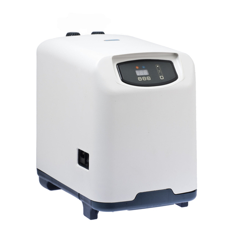
TECO CP5 Service manual

TECO S.r.l. – Via G. Ricci Curbastro, 8 – 48124 Fornace Zarattini – Ravenna (Italy) – Tel. +39 0544 408333 – Fax +39 0544 280084 www.tecoonline.com
[email protected] Reg.Imprese di Ravenna, C.F. e P.IVA 01075610392 –R.E.A.n.118737 - Cap.Soc. 60.000 Euro – Registro A.E.E. IT08020000002839
The information contained within this manual may be subject to changes without prior notice by TECO.
Pag. 1 di 15
INSTALLATION, USE AND MAINTENANCE MANUAL
CPA# CHILLER LINE
Model: CP5
Language: English - art. cod. 6.1.199.0.00 - 09/2023

TECO S.r.l. – Via G. Ricci Curbastro, 8 – 48124 Fornace Zarattini – Ravenna (Italy) – Tel. +39 0544 408333 – Fax +39 0544 280084 www.tecoonline.com
[email protected] Reg.Imprese di Ravenna, C.F. e P.IVA 01075610392 –R.E.A.n.118737 - Cap.Soc. 60.000 Euro – Registro A.E.E. IT08020000002839
The information contained within this manual may be subject to changes without prior notice by TECO.
Pag. 2 di 15
Introduction
This installation, use, and maintenance manual has been prepared for those responsible for installing the
appliance and for those tasked with using or operating the appliance. We recommend that you carefully read
this manual, follow safety precautions, and ensure proper installation.
The user manual contains important instructions and information on how the appliance can be used safely,
professionally, and economically.
This manual is intended to be consulted by all individuals involved in the lifecycle of the appliance and
should therefore be kept and made accessible to the user at all times.
The chiller may only be installed and used after reading this manual in its entirety and following the
instructions provided therein.

TECO S.r.l. – Via G. Ricci Curbastro, 8 – 48124 Fornace Zarattini – Ravenna (Italy) – Tel. +39 0544 408333 – Fax +39 0544 280084 www.tecoonline.com
[email protected] Reg.Imprese di Ravenna, C.F. e P.IVA 01075610392 –R.E.A.n.118737 - Cap.Soc. 60.000 Euro – Registro A.E.E. IT08020000002839
The information contained within this manual may be subject to changes without prior notice by TECO.
Pag. 3 di 15
IMAGES

TECO S.r.l. – Via G. Ricci Curbastro, 8 – 48124 Fornace Zarattini – Ravenna (Italy) – Tel. +39 0544 408333 – Fax +39 0544 280084 www.tecoonline.com
[email protected] Reg.Imprese di Ravenna, C.F. e P.IVA 01075610392 –R.E.A.n.118737 - Cap.Soc. 60.000 Euro – Registro A.E.E. IT08020000002839
The information contained within this manual may be subject to changes without prior notice by TECO.
Pag. 4 di 15

TECO S.r.l. – Via G. Ricci Curbastro, 8 – 48124 Fornace Zarattini – Ravenna (Italy) – Tel. +39 0544 408333 – Fax +39 0544 280084 www.tecoonline.com
[email protected] Reg.Imprese di Ravenna, C.F. e P.IVA 01075610392 –R.E.A.n.118737 - Cap.Soc. 60.000 Euro – Registro A.E.E. IT08020000002839
The information contained within this manual may be subject to changes without prior notice by TECO.
Pag. 5 di 15
WIRING DIAGRAM

TECO S.r.l. – Via G. Ricci Curbastro, 8 – 48124 Fornace Zarattini – Ravenna (Italy) – Tel. +39 0544 408333 – Fax +39 0544 280084 www.tecoonline.com
[email protected] Reg.Imprese di Ravenna, C.F. e P.IVA 01075610392 –R.E.A.n.118737 - Cap.Soc. 60.000 Euro – Registro A.E.E. IT08020000002839
The information contained within this manual may be subject to changes without prior notice by TECO.
Pag. 6 di 15
ENGLISH
SUMMARY
1. INSTRUCTION MANUAL ...................................................................................................... 7
1.1 PREFACE ....................................................................................................................... 7
1.1.1 IMPORTANT WARNINGS ............................................................................................. 7
1.2 PERSONNEL QUALIFICATIONS ........................................................................................... 8
1.3 WARRANTY ....................................................................................................................... 8
1.4 MANUAL ORGANIZATION/CONSULTATION METHODS ....................................................... 8
1.4.1 MANUAL STRUCTURE ................................................................................................. 8
1.4.2 DESCRIPTION OF PICTOGRAMS ................................................................................... 8
1.5 PRODUCT DESCRIPTION .................................................................................................... 8
1.5.1 TECHNICAL DATA AND SPECIFICATIONS ...................................................................... 9
1.6 GENERAL CONDITIONS OF USE .......................................................................................... 9
1.6.1 ALOWED USES ............................................................................................................ 9
1.6.2 PROHIBITED USES ....................................................................................................... 9
1.7 INSTALLATION AND OPERATION ..................................................................................... 10
1.7.1 PACKAGE CONTENTS ................................................................................................ 10
1.7.2 UNPACKING THE APPLIANCE .................................................................................... 10
1.7.3 APPLIANCE INSTALLATION AND OPERATION ............................................................. 10
1.7.4 ELECTRICAL CONNECTION ......................................................................................... 11
1.7.5 TURNING ON, OPERATION, AND TURNING OFF OF THE APPLIANCE ........................... 11
1.7.6 DISPLAY INDICATIONS .............................................................................................. 12
1.7.7 THERMOSTAT ADJUSTMENT ..................................................................................... 12
1.8 TRANSPORT AND STORAGE ............................................................................................. 12
1.9 DISMANTLING AND DISPOSAL ......................................................................................... 12
1.10 MAINTENANCE ............................................................................................................. 13
1.10.1 CLEANING .............................................................................................................. 13
1.11 DIAGNOSTICS, ISSUES, CAUSES, AND REMEDIES ............................................................ 13
2. SPARE PARTS .................................................................................................................... 13
3. TABLE OF ISSUES, CAUSES, AND REMEDIES ........................................................................ 14

TECO S.r.l. – Via G. Ricci Curbastro, 8 – 48124 Fornace Zarattini – Ravenna (Italy) – Tel. +39 0544 408333 – Fax +39 0544 280084 www.tecoonline.com
[email protected] Reg.Imprese di Ravenna, C.F. e P.IVA 01075610392 –R.E.A.n.118737 - Cap.Soc. 60.000 Euro – Registro A.E.E. IT08020000002839
The information contained within this manual may be subject to changes without prior notice by TECO.
Pag. 7 di 15
1. INSTRUCTION MANUAL
1.1.1 IMPORTANT WARNINGS
All reproduction rights of this manual are reserved by TECO S.r.l. This manual may not be shown to third
parties without written authorization from TECO S.r.l. The text may not be used in other publications without
written authorization from TECO S.r.l. The descriptions and illustrations in this publication are not binding,
while maintaining the essential characteristics of the described type of chiller or air conditioner. The company
reserves the right to make any modifications it deems necessary for product improvement, constructional or
commercial needs, at any time and without committing to promptly update this publication. The updated version
of this manual is available at "www.tecoonline.eu/resources".
THIS MANUAL IS THE PROPERTY OF TECO S.r.l. ANY REPRODUCTION, EVEN IN PART, IS
PROHIBITED. © TECO S.r.l.
NOTE: Please keep these instructions for future reference.
Do not insert fingers or foreign objects into the air grilles. This may cause injuries due to blade rotation.
Do not scratch or pull the power cord.
If you notice an anomaly (burning smell, etc.), disconnect the power and contact the dealer. If the unit
continues to operate abnormally, there is a risk of fire, breakage, etc.
If the power cord is damaged, it must be replaced by the manufacturer, dealer, or qualified technical
personnel to avoid hazards.
Repairs should not be carried out by the user but only by technical personnel. Incorrectly performed
repairs can lead to fire or electrical shock.
Disconnect the power before performing any maintenance on the aquarium.
Ensure that the electrical supply characteristics match those indicated on the "technical data" plate
affixed to the appliance.
WARNING: This product is not suitable for children under eight years of age. It is essential to
ensure that children do not play with the device. This device is not intended for use by persons
(including children) with limited physical, sensorial or mental abilities, or lacking in experience and
know-how, unless supervision or instructions for using the device are provided by the person
responsible for their safety. Cleaning and maintenance shall not be made by children without
supervision.
WARNING: Modifications or repairs made by the user without written authorization from TECO
S.r.l. will void the warranty and release TECO S.r.l. from any liability for damages caused by a defective
product. The same considerations apply when using non-original or different replacement parts not
explicitly indicated by TECO S.r.l.
WARNING: Provide adequate ventilation for the chiller, and do not obstruct the free flow of air
around the chiller.
WARNING: Do not damage the refrigerant circuit.
WARNING: The appliance contains flammable R290 gas. Any service work must be performed
exclusively by experienced personnel trained in R290 gas handling procedures.
WARNING: To prevent hazards due to the appliance's instability, it must be properly secured
according to the instructions.
WARNING: Before disconnecting the appliance from the pipes, it is necessary to clamp the tubes
with the appropriate clamps (Ref. B5 Fig. 10) to prevent water from leaking out of the aquarium. Once
the appliance is reconnected, reopen the appropriate clamps (Ref. P6 Fig. 10). The operator must be
able to verify from all accessible positions that the plug remains disconnected.

TECO S.r.l. – Via G. Ricci Curbastro, 8 – 48124 Fornace Zarattini – Ravenna (Italy) – Tel. +39 0544 408333 – Fax +39 0544 280084 www.tecoonline.com
[email protected] Reg.Imprese di Ravenna, C.F. e P.IVA 01075610392 –R.E.A.n.118737 - Cap.Soc. 60.000 Euro – Registro A.E.E. IT08020000002839
The information contained within this manual may be subject to changes without prior notice by TECO.
Pag. 8 di 15
1.2 PERSONNEL QUALIFICATIONS
All personnel involved in the operation, installation, inspection, and maintenance of the appliance must be
qualified to perform their assigned tasks. If the personnel do not already possess the necessary knowledge
and skills, appropriate training and education must be provided. Always organize repair activities with
consideration for the activity, health, and safety of the personnel, and ensure compliance with all safety
requirements for the appliance, adhering to the regulations and laws in force concerning safety and health.
REQUIRED QUALIFICATIONS:
CERTIFIED REFRIGERATION TECHNICIAN FOR USE WITH FLAMMABLE REFRIGERANTS:
Qualified technician capable of working on refrigeration systems containing flammable refrigerants.
1.3 WARRANTY
The appliances manufactured by TECO S.r.l. are covered by a WARRANTY provided by the authorized
dealer from whom the purchase was made, as required by the legal provisions of the country in which they
are marketed. If, during the validity period, there are faulty operations or malfunctions of appliance parts that
fall within the warranty terms, the authorized dealer, after appropriate checks on the appliance, will proceed
with the repair or replacement of the defective parts. To claim warranty coverage, it is necessary to provide
the documentation required by the legal provisions of the country in which the appliance is marketed, and
comply with the conditions specified by your dealer or TECO's authorized service center.
1.4 MANUAL ORGANIZATION/CONSULTATION METHODS
1.4.1 MANUAL STRUCTURE
The manual is divided into chapters, which gather all the necessary information by topic to use the product
without any risk.
1.4.2 DESCRIPTION OF PICTOGRAMS
The purpose of safety signage is to quickly and easily draw attention to areas where it has not been possible
to eliminate residual risks inherent in operation. Below are the safety symbols applied and their meanings:
WARNING: This symbol indicates safety regulations for the operator and/or any exposed
individuals.
CAUTION: This symbol signifies the possibility of causing damage to the product and/or its
components.
NOTE: This symbol conveys useful information.
This symbol is a warning and indicates a fire hazard or flammable material.
This symbol is a warning and indicates an electrical hazard.
This symbol indicates an earth terminal for protection against electrical shocks.
This symbol indicates to read the manual carefully.
1.5 PRODUCT DESCRIPTION
The appliance is suitable for cooling the water contained in tanks for domestic and/or commercial sports
recovery. The appliance must not be used for purposes other than those specified above. Using it for purposes
other than its intended use may lead to hazardous conditions.

TECO S.r.l. – Via G. Ricci Curbastro, 8 – 48124 Fornace Zarattini – Ravenna (Italy) – Tel. +39 0544 408333 – Fax +39 0544 280084 www.tecoonline.com
[email protected] Reg.Imprese di Ravenna, C.F. e P.IVA 01075610392 –R.E.A.n.118737 - Cap.Soc. 60.000 Euro – Registro A.E.E. IT08020000002839
The information contained within this manual may be subject to changes without prior notice by TECO.
Pag. 9 di 15
1.5.1 TECHNICAL DATA AND SPECIFICATIONS
Specifications
Model
CP 5
Power supply¹ 230V - 50Hz
Power Consumption 440 W
Water Inlet/Outlet 16 mm - 3/4 in
Water flow² 900 l/h ÷ 1200 l/h - 238 USgal/h ÷ 317 USgal/h
Maximum Pressure 100 kPa - 1 bar - 14,4 PSI
Weight 25 kg - 54,9 lb
Dimensions 310 x 310 x 500 (h) mm - 12,2 x 12,2 x 19,69 (h) in
Refrigerant¹ R290
All data is indicative and subject to change without notice by TECO.
Refer to the technical data label Ref. A3 Fig.4. Contact TECO for other power supplies.
²The indicated flow is the actual flow, not the maximum flow of the pump. Please contact the distributor for pump selection.
Tab. 3-1
1.6 GENERAL CONDITIONS OF USE
1.6.1 ALLOWED USES
To correctly use the appliance, it is advisable to follow the following guidelines:
The appliance described in this manual has been specifically designed for cooling water.
The appliance is suitable for operation in environments with an ideal operating temperature between
+16°C and +32°C (60°F – 90°F).
The appliance must be installed on a flat surface.
Any operation involving manual actions on the appliance must only be done when the appliance is
stationary.
.
1.6.2 PROHIBITED USES
Using the appliance in contrast to the recommended usage guidelines constitutes non-compliant usage.
Here are the guidelines:
It is prohibited to use the appliance in areas with high heat and direct radiation exposure.
It is prohibited to use the appliance in areas with potentially explosive atmospheres.
It is prohibited to use the appliance in excessively dusty areas and/or in the presence of a high
concentration of solid particulates in the air.
It is prohibited to introduce water into the refrigeration unit at a temperature exceeding 30°C (86°F)
or lower than 5°C (41°F).

TECO S.r.l. – Via G. Ricci Curbastro, 8 – 48124 Fornace Zarattini – Ravenna (Italy) – Tel. +39 0544 408333 – Fax +39 0544 280084 www.tecoonline.com
[email protected] Reg.Imprese di Ravenna, C.F. e P.IVA 01075610392 –R.E.A.n.118737 - Cap.Soc. 60.000 Euro – Registro A.E.E. IT08020000002839
The information contained within this manual may be subject to changes without prior notice by TECO.
Pag. 10 di 15
1.7 INSTALLATION AND OPERATION
1.7.1 PACKAGE CONTENTS
Upon opening the cardboard box, please check for the presence of all accessories (Fig. 5):
D Extension conveyor 1
E Conveyor 1
F Installation, usage, and maintenance manual 1
H Adhesive drilling template for the hot air outlet 1
I Cable ties for securing tubes 4
L Air conveyor fixing key 1
M Tube connection fittings complete with gaskets 2
N Tube clamps 2
Verify through the technical data label (Ref. A3 Fig. 4) that the appliance contained in the packaging
matches the purchased model.
1.7.2 UNPACKING THE APPLIANCE
WARNING: Do not overturn the packaging or the appliance. Keep the packaging intact for future
handling.
1) Open the packaging and remove the accessories (Ref. A Fig. 2).
2) Remove the contents without turning them over; gripping them by the side handles (Ref. B Fig. 3).
3) Remove the polystyrene (Rif.C Fig.3).
4) Remove the plastic bag.
1.7.3 APPLIANCE INSTALLATION AND OPERATION
WARNING: Installation must not be carried out by the user but only by qualified technicians.
1) Do not install or attempt to repair the appliance if it has been damaged during transport.
2) Do not connect the power cord to the electrical supply unless specifically required..
3) To ensure the proper operation of the appliance under safe conditions, it is strictly forbidden to expose it to
weather conditions and direct heat sources (Fig. 1). The temperature in the installation environment should be
between 16°C and 32°C (60°F – 90°F).
4) Position the refrigerator so that the refrigerator itself and the parts containing live parts are not accessible
in any way to a person inside the tank.
5) Position the chiller in a way that it cannot fall into the tank under any circumstances
6) Choose the direction for the hot air outlet by rotating the conveyor (Ref. O Fig. 6) and secure it by turning
the two screws a quarter turn counterclockwise (Ref. Q Fig. 6) using the provided wrench (Ref. P Fig. 6).
7) If the installation is not inside a technical compartment, proceed to step 10.
8) If the installation is inside a technical compartment, make an opening on the chosen wall for the evacuation
of hot air, respecting the recommended minimum distances (Fig. 7). The supplied label (Ref. B9 Fig. 7) can
be helpful. The minimum internal dimensions of the cabinet are 390x390x525(h) mm; 15.35x15.35x20.67(h)
in.
9) Provide an opening of 400 cm² – 62 in² to allow air to enter the compartment (Ref. P1 Fig. 8).
Tab. 1-1
10) Prepare the tubes as follows:
10.1) If necessary, first slide on the tube clamp (Ref. P2 Fig. 9) and then the tube locking clamp (Ref. P3 Fig.
9).
10.2) Insert the fitting (Ref. P4 Fig. 9) into the tube and bring the tube locking clamp over the fitting (Ref. P5
Fig. 9).
10.3) Rotate the fitting (Ref. P7 Fig. 11) clockwise, orienting it according to your needs, and tighten it securely.
Hot Air Exhaust Opening Position
S 260 mm – 10,24 in
T 74 mm – 2,91 in
U > 60 mm – 2,36 in
V CP 5 427 mm – 16,8 in
Minimum distances from the walls
Z (filter side) 30 mm – 1,18 in
X (Cable output side)
50 mm – 1,97 in

TECO S.r.l. – Via G. Ricci Curbastro, 8 – 48124 Fornace Zarattini – Ravenna (Italy) – Tel. +39 0544 408333 – Fax +39 0544 280084 www.tecoonline.com
[email protected] Reg.Imprese di Ravenna, C.F. e P.IVA 01075610392 –R.E.A.n.118737 - Cap.Soc. 60.000 Euro – Registro A.E.E. IT08020000002839
The information contained within this manual may be subject to changes without prior notice by TECO.
Pag. 11 di 15
10.4) When connecting the tubes, ensure that the tube coming from the pump (not provided) (Ref. A1 Fig. 12-
13) and/or from the filter unit (not provided with the appliance) (Ref. A2 Fig. 12) is connected to the position
marked as IN (Ref. P8 Fig. 11), and that the water outlet tube from the refrigerator is connected to the position
marked as OUT (Ref. P9 Fig. 11).
11) Position the appliance in the chosen location, ensuring visibility of the instrument.
CAUTION: The appliance must be installed at a height lower than the water level.
CAUTION: Do not position the appliance above the tank.
WARNING: When positioning the appliance, ensure that the power cord is not trapped or damaged.
12) Start the pump if necessary. If needed, reopen the tube clamps (Ref. P6 Fig. 10). Ensure that the water
circulates smoothly within the circuit and that there are no leaks. In case of hydraulic circuit anomalies or leaks,
review the connections. Verify that the water flow matches the requirements specified in Table Tab.3-1. If the
flow is too high, restrict the pipes until the required flow is achieved. If the flow is too low, consider using a
more powerful pump.
13) CAUTION: To avoid damage, the appliance cannot operate without water circulation (pump off)
and with an actual water flow different from what is indicated in Table Tab. 3-1.
CAUTION: Ensure that the water supplied to the appliance is filtered.
14) With the pump in operation, make the electrical connection of the chiller to the electrical network as
described in point 14. The display will show the word OFF.
1.7.4 ELECTRICAL CONNECTION
The appliance, before being placed on the market, has undergone
electrical and functional testing.
The appliance is supplied with the power cord. The installer must connect
the appliance in compliance with current safety regulations.
Check the integrity of the power cord.
Connect the brown wire to the phase of the system, the blue wire to the
neutral of the system, and the yellow-green wire to the ground.
Ensure that the circuit supplying power to the appliance is protected by a
residual current circuit breaker with a nominal tripping current not
exceeding 30 mA.
WARNING: Ensure that the power cord is never subjected to tension and is not placed in contact
with heat sources.
WARNING: Check the integrity of the power cord.
WARNING: Ensure that the electrical supply characteristics match those indicated on the technical
data label applied on the back of the appliance (Ref. A3 Fig. 4).
WARNING: Ensure that the power cord is never subjected to tension and is not placed in contact
with heat sources.
WARNING: The chiller must be permanently connected to the fixed electrical network, and the
connection must be equipotential.
WARNING: The chiller must be powered through a residual current circuit breaker with a nominal
tripping current not exceeding 30 mA.
1.7.5 TURNING ON, OPERATION, AND TURNING OFF OF THE APPLIANCE
1) By pressing the power button (Ref. A7 Fig. 15) for at least 3 seconds, your appliance will start functioning,
and the water temperature will be displayed on the screen. To view the target temperature, press the SET
button (Ref. A8 Fig. 15). To return to the current water temperature, press the SET button again (Ref. A8 Fig.
15) or wait for 5 seconds.
2) CAUTION: To prevent compressor damage, a 2-minute delay has been programmed for the initial
startup.
3) To stop the appliance, press the power button (Ref. A7 Fig. 15) for at least 3 seconds, and the display will
show "OFF.".

TECO S.r.l. – Via G. Ricci Curbastro, 8 – 48124 Fornace Zarattini – Ravenna (Italy) – Tel. +39 0544 408333 – Fax +39 0544 280084 www.tecoonline.com
[email protected] Reg.Imprese di Ravenna, C.F. e P.IVA 01075610392 –R.E.A.n.118737 - Cap.Soc. 60.000 Euro – Registro A.E.E. IT08020000002839
The information contained within this manual may be subject to changes without prior notice by TECO.
Pag. 12 di 15
1.7.6 DISPLAY INDICATIONS
On: Appliance in cooling mode (Ref. A9 Fig. 15).
On: Appliance in heating mode (NOT ACTIVE) (Ref. B1 Fig. 15).
Flashing: Appliance ready for cooling (Ref. A9 Fig. 15).
On: Alarm condition (Ref. A1 Fig. 15).
1.7.7 THERMOSTAT ADJUSTMENT
Refer to Figure 15 for button identification
1) The water temperature can be set between 5°C and 15°C (41°F - 59°F). To change it:
a. Press and hold the SET button (Ref. A8) for 3 seconds. The currently set value will be displayed, and the
unit of measurement icon (C or F Ref. C3) will start flashing.
b. Adjust the value using the buttons. and (Rif. C2 e A7).
c. Press the SET button (Ref. A8) to confirm the set value.
2) To adjust other parameters such as operating hysteresis (Hy) or sensor calibration (Ot). Access the
programming menu by pressing and holding the SET+ (Ref. A8 e A7). The icon of the selected unit of
measurement begins to flash (C or F Ref. C3) and Hy appears. Scroll through the parameters using the buttons
and (Ref. C2 and A7) until you see the desired parameter.
f. Press the SET button (Ref. A8), and the currently set value will be displayed.
g. Adjust the value using the buttons and (Ref. C2 e A7).
h. Press the SET button (Ref. A8) to confirm the set value and proceed to the next parameter.
i. Press SET + (Ref. A8 and C2) to exit the programming mode.
NOTE: If no button is pressed for 30 seconds, all the set values will be saved, and the appliance
will be ready to operate.
Parameter Pre-set Value
Description
Adjustment
Range
Hy 1°C This parameter regulates the hysteresis, which is the
differential for the operation of the appliance
0,5 ÷ 10°C
1 ÷ 45°F
rL xx.x Thermostat firmware version.
Read-only parameter. -
Tab. 1-2
1.8 TRANSPORT AND STORAGE
The appliance should be handled gently and positioned in an upright position using the provided handles. It
should be placed on a flat surface.
1.9 DEMOLITION AND DISPOSAL
The label with the crossed-out waste bin symbol on the product indicates that the product should
not be disposed of through the normal household waste disposal procedure. To prevent potential
harm to the environment and human health, please separate this product from other household
waste so that it can be recycled in accordance with environmentally responsible procedures. For
more information on available collection centers, please contact your local government office or
the product retailer. These instructions apply only to customers within the European Union, in accordance with
the European Parliament directive on Waste Electrical and Electronic Equipment (WEEE) and the regulations
governing its transposition and implementation into various national legal systems. For other countries, please
contact your local government to explore the possibility of recycling your product.

TECO S.r.l. – Via G. Ricci Curbastro, 8 – 48124 Fornace Zarattini – Ravenna (Italy) – Tel. +39 0544 408333 – Fax +39 0544 280084 www.tecoonline.com
[email protected] Reg.Imprese di Ravenna, C.F. e P.IVA 01075610392 –R.E.A.n.118737 - Cap.Soc. 60.000 Euro – Registro A.E.E. IT08020000002839
The information contained within this manual may be subject to changes without prior notice by TECO.
Pag. 13 di 15
1.10 MAINTENANCE
Scheduled routine maintenance includes inspections, checks, and interventions that systematically monitor
the condition of various parts to prevent interruptions and breakdowns. These operations must be carried out
by Qualified Personnel. Maintenance tasks should be performed in accordance with the times indicated in the
following table:
Component Frequency Operation
Appliance
Every month Check the tightening of the components.
Every year Check the integrity of electrical components and electrical cables
Every year Efficiency and safety checks
Every year Inspection of informative labels
Fan Every month Check the operation.
Capacitor Every month Visual inspection to check if it is clean or not.
Compressor Every month Check the mechanical operation.
Filter Every month Check and clean
Tab. 1-3
1.10.1 CLEANING
Cleaning the filter should be done at least once a month and as needed based on the level of dustiness in the
installation environment. Open the plastic grille (Ref. A6, Fig. 14) from the top and remove the filter (Ref. A5,
Fig. 14). Clean the filter by washing it with lukewarm water.
CAUTION: Do not use hard brushes or abrasive materials to avoid damaging the filter.
Reposition the filter (Ref. A5, Fig. 14) and close the plastic grille (Ref. A6, Fig. 14).
1.11 DIAGNOSTICS, ISSUES, CAUSES, AND REMEDIES
Below, we present a table that is useful for the operator to recognize the defects observed in the operation.
Repairs on the appliance will be carried out by a specialized and trained maintenance technician.
2. SPARE PARTS
To ensure satisfactory and consistent operation, it is necessary to use exclusively original parts and
accessories. The use of non-original spare parts is not recommended. In the event that this occurs, Teco S.r.l.
disclaims any responsibility for any damage to persons or property resulting from non-compliance with the
above instructions.
3. TABLE OF ISSUES, CAUSES, REMEDIES Tab. 2-1
Issues
Causes
Remedies
The display doesn’
t
turn on Loss of electrical power.
Check that the plug is fully inserted into the power
outlet (Ref. A5, Fig. 4).
Poor water cooling.
Insufficient water flow.
Check the proper operation of the pump (not
supplied) (Ref. A1, Fig. 12-13).
Insufficient thermal insulation.
Provide insulation for the tank walls and pipes to
reduce thermal losses.
Air exiting from the ventilation
grille at room temperature.
Lack of refrigerant in the compressor, please
contact the local TECO S.r.l. dealer.

TECO S.r.l. – Via G. Ricci Curbastro, 8 – 48124 Fornace Zarattini – Ravenna (Italy) – Tel. +39 0544 408333 – Fax +39 0544 280084 www.tecoonline.com
[email protected] Reg.Imprese di Ravenna, C.F. e P.IVA 01075610392 –R.E.A.n.118737 - Cap.Soc. 60.000 Euro – Registro A.E.E. IT08020000002839
The information contained within this manual may be subject to changes without prior notice by TECO.
Pag. 14 di 15
Issues
Causes
Remedies
On the display, the
message “HA2”
appears
(overheating).
Dirty air filter. Clean the filter as indicated in the Cleaning
chapter.
Room temperature too high.
Restore optimal environmental conditions. The
maximum allowable room temperature is 32°C
(90°F)
Blocked ventilation ducts. Clear the vents or place the conditioner in a
suitable environment.
Ventilation system malfunction. Contact the local TECO S.r.l. dealer.
On the display, the
message “P1”
appears
Water temperature probe
malfunction. Contact the local TECO S.r.l. dealer.
On the display, the
message “P2”
appears
Overheating probe malfunction. Contact the local TECO S.r.l. dealer.
On the display, the
message “HA”
appears.
High water temperature.
Check the proper operation of the pump (not
provided) (Ref. A1 Fig. 12-13).
Ensure that there are no pipe obstructions.
Verify that the cooling function is active.
On the display, the
message “LA”
appears.
Low water temperature.
Check the proper operation of the pump (not
provided) (Ref. A1 Fig. 12-13).
Ensure that there are no pipe obstructions.
The temperature
displayed on the
device's screen
does not match the
actual temperature
of the aquarium
The water does not circulate
correctly within the hydraulic
circuit.
Ensure that there are no pipe obstructions.
Check the efficiency of the pump (not provided).
Long and uninsulated pipes. Shorten the pipes as much as possible and
thermally insulate them.

TECO S.r.l. – Via G. Ricci Curbastro, 8 – 48124 Fornace Zarattini – Ravenna (Italy) – Tel. +39 0544 408333 – Fax +39 0544 280084 www.tecoonline.com
[email protected] Reg.Imprese di Ravenna, C.F. e P.IVA 01075610392 –R.E.A.n.118737 - Cap.Soc. 60.000 Euro – Registro A.E.E. IT08020000002839
The information contained within this manual may be subject to changes without prior notice by TECO.
Pag. 15 di 15
Table of contents
Other TECO Chiller manuals

TECO
TECO SEACHILL TK 2800 User manual

TECO
TECO TK Series Instruction Manual

TECO
TECO JSDG2S Series User manual

TECO
TECO TK3000 User manual

TECO
TECO Tank TK 150 Instruction Manual

TECO
TECO TK Series Instruction Manual

TECO
TECO TR 10 User manual

TECO
TECO ra 200 User manual

TECO
TECO TK Series Instruction Manual

TECO
TECO seachill tr5 User manual
Popular Chiller manuals by other brands

D-D The Aquarium Solution
D-D The Aquarium Solution DC750 Product user manual

Emerson
Emerson Fluid Chiller user manual

lancer
lancer PRESTO Installation, operation & service manual

AERMEC
AERMEC NRB Series Installation and maintenance manual

Trane
Trane 2TTZ9C Installer's guide

Traulsen
Traulsen KROGER RBC100 Specifications