Valve Assembly
Plumbing
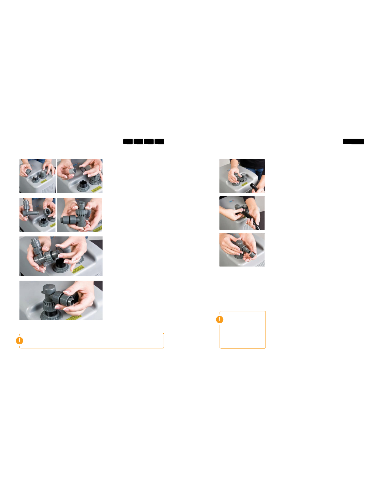
1
Unscrew the Ring Nuts for the
shut off valves from the chiller
inlet and outlet. Remove the In/
Out plugs from the In/Out ports
ofthe chiller. Removethe O-rings
SeaChill Chillers can be plumbed using flexible plastic tubing or hard
plumbedusingPVC.
Flexible Tubing
Above photos are of a TR5 model
from In/Out plugs. (do not discard
In/Out plugs–store for use should
you ever need to transport or ship
the chiller to another location).
2
Slide the Ring Nutsonto the Shut
Off Valves past the two small clips
of plastic projecting from the side
of the Shut Off Valves.
Note: Once Ring Nuts have been
pushed past the plastic clips on the Shut
Off Valves, do not remove Ring Nut
from Shut Off Valves, this will break the
plastic clips, causing the valve to leak.
3
Roll the O Rings onto the Shut
Off Valve below the Ring Nut.
Do not push O Ring past plastic
clips on Shut Off Valves.
4
Place the Shut Off Valve into
the Outlet of the chiller, do not
use much force. Hand tighten
the Ring Nuts to seat the O-Ring
and attach the Shut Off Valve
Securely to the chiller.
Note: the first nipple on the Shut Off
Valves will take 5/8” id tubing. The
second, larger nipple will accept 3/4” id
tubing. Remove compresssion fitting for
5/8” tubing before using 3/4” tubing.
Use the tubing size you prefer.
1
PVC
1
2
3
4
Attach flexible plastic tubing from the pump to the chiller
by sliding tubing over nipple on Shut Off Valves. Tighten
Compression Fitting over the end of the flexible plastic tubing
byturningfittingcounter-clockwise until tubing is secure.
Note: If the chiller should ever need maintenance, it will be necessary to remove the
chiller cover. Do not hard plumb PVC to the chiller. Plan ahead and use ball valves or
gate valves to allow water flow to be shut off. Install unions to allow for the removal
of the chiller cover.
Recommended PVC parts
(may be either schedule 40 or schedule 80 PVC)
For installation using PVC solvent socket type fittings:
•
1” FPT x Slip adapters (2)
•
1” PVC pipe, 1” Slip x Slip Ball Valves (2)
•
1” Slip X Slip Unions (2)
•
Teflon tape or pipe thread sealant with Teflon
Unscrewthe Ring Nuts for the shut off valves from the chiller inlet
andoutlet.RemovetheIn/OutPlugsfromthe In/Out portsof
the chiller (do not discard In/Out plugs –store for useshould you
everneedto transportor shipthechillerto anotherlocation).
Keep the Housing Ring Nuts in place, wrap the male threaded
inlet and outlet from the chiller in Teflon tape or pipe thread
sealant with teflon to prevent leaks. Wrap Teflon tape at least
twice around threads. Check carefully for leaks. Slow leaks
may occur.
Screw the 1” FPT x Slip adapters over inlet and outlet to chiller.
Tightenfirmly but do not use excessive force.
Assemble the remaining PVC as you wish making sure you can
easily unscrew the 1” FPT x Slip adapters to maintenance the
chillerifnecessary.