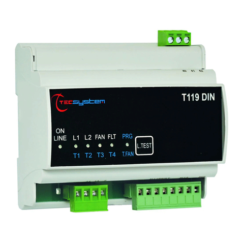
TECSYSTEM T119 Manual

http://www.tecsystem.it
T119
T119 DIN
INSTALLAZIONE E
PROGRAMMAZIONE
TECSYSTEM S.r.l.
20094 Corsico (MI)
Tel.: +39-024581861
Fax: +39-0248600783
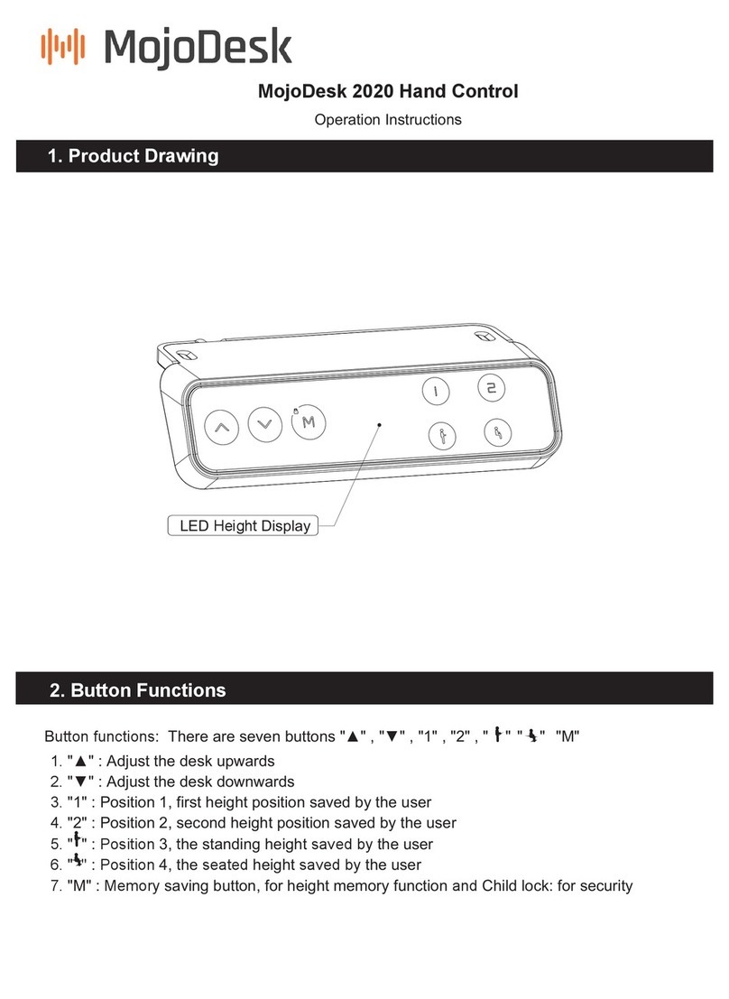
T119
TECSYSTEM S.r.l ®
R. 1.5 07/09/12
• Italiano

2T119
TECSYSTEM S.r.l ®
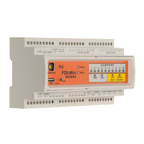
La T119 rappresenta quanto di più avanzato esista oggi sul mercato per il controllo della temperatura di tra-
sformatori di MT inglobati in resina, che utilizzano sensori PTC. L’apparecchio fornisce i segnali di pre-allarme
L1 e allarme-sgancio TRIP quando sono raggiunti i limiti di temperatura rilevati dalle PTC inserite negli avvol-
gimenti. La T119 è predisposta per controllare la ventilazione di raffreddamento del trasformatore. Il vantaggio
offerto dalla T119 è quello di diagnosticare continuamente lo stato delle sonde PTC e qualora una di queste si
dovesse rompere, si ha istantaneamente un segnale di sonda in avaria. Il relay di FAN resta eccitato sino a
che la temperatura resta superiore al valore di dNAT; quando la temperatura scende al di sotto di tale valore il
relay resta ancora eccitato per il tempo (5-10-20-40’) di ventilazione impostato (funzione DELAY OFF). Dato
che le PTC attualmente prodotte dai vari costruttori europei hanno caratteristiche variabili tra loro, Tecsystem
Srl non risponde dei malfunzionamenti del sistema di controllo causati da PTC che hanno valori di re-
sistenza diversi da quelli indicati nella tabella seguente (tabella 1):
ALIMENTAZIONE
• valori nominali 24-240 Vca-cc
• max.valori sopportabili 20-270 Vca-cc
• Vcc con polarità invertibili
DIMENSIONI T119
• 48x96mm-DIN43700-prof.150mm (compreso mor-
settiera)
• foro pannello 44x92mm
DIMENSIONI T-119 DIN
• 106x58 mm DIN43880 prof.90 mm
INGRESSI
• 3 gruppi in serie di ingressi Ptc
• -1 serie per ALL1
• -1 serie per ALL2
• - 1 serie per FAN
• collegamenti su morsettiere estraibili
• canali ingresso protetti contro i disturbi elettroma-
gnetici
USCITE
• 2 relays di allarme (ALL1-ALL2-FAULT)
• 1 relay di gestione ventilazione (FAN) con autorite-
nuta temporizzata (5-10-20-40 min.) delay OFF
• relay di uscita con contatti da 5A-250Vca
TEST E PRESTAZIONI
• costruzione in accordo normative CE
• protezione contro disturbi elettrici CEI-EN50081-
2/50082-2
• rigidità dielettrica 2500 Vca per 1 minuto tra relay
di uscita e sonde, relay e alimentazione, alimenta-
zione e sonde
• temperatura di lavoro da -20°C a +60°C
• umidità ammessa 90% senza condensa
• contenitore in ABS autoestinguente NORYL 94V0
• opz. trattamento protettivo parte elettronica
• frontale in policarbonato IP54
• assorbimento 2VA
• memoria dati 10 anni minimo
• circuito di autodiagnosi
• (*)Test di vibrazioni IEC 68-2-6
Ampiezza ± 1 mm da 2Hz a 13.2Hz
Accelerazione ± 0.7G da 13.2Hz a 100Hz.
• (*)Test sismico secondo la normativa IEEE 344-
1.987
*T119 Cross reference T154 per analogia costruttiva.
VISUALIZZAZIONE E GESTIONE DATI
• LED indicanti il canale in allarme, lo sgancio o il fan
• LED indicante il FAULT
• 2 soglie di allarme
• 1 soglia controllo ON ventilazione
• accesso alla programmazione tramite pulsante
frontale
• uscita automatica dalla programmazione dopo 1
minuto di inattività
1) CARATTERISTICHE TECNICHE
FUNZIONE RESISTENZA PER SINGOLA PTC O MULTIPLA IN SERIE
NON ALLARME
Temperatura della macchina sotto le so-
glie di allarme
MAGGIORE DI 50 OHM
ALLARME
Raggiungimento delle soglie di allarme di
FAN-ALL-TRIP
MAGGIORE DI 1800 OHM
FOC diagnostica di sonda interrotta MAGGIORE DI 200 KOHM Con incremento rapido Í 3”
FCC diagnostica di sonda in c.c. MINORE DI 15 OHM

3
T119
TECSYSTEM S.r.l ®
2) USO E PROGRAMMAZIONE
Programmazione del ciclo di ventilazione
passo azione effetto
1 accendere l’unità si accende il LED verde
2 premere TEST per due volte in sequenza il led rosso PRG lampeggia
3 entro 5” premere TEST fino ad avere il led PRG
acceso fisso il led PRG è acceso fisso
4 entro 5” premere TEST per scegliere il tempo di
FAN
il led rosso commuta da T1-T2-T3-T4
(tempo di FAN 5’-10’-20’-40’)
5
fermarsi dal premere TEST quando il led è sul Tx
corrispondente al tempo desiderato. Attendere che
tutti i leds si spengano.
6 fine della programmazione tutti i leds sono spenti
7 spegnere e riaccendere l’unità
Per scegliere il tempo di FAN (passo 4):
Premere una volta TEST per selezionare 5’ (T1 acceso)
Premere due volte TEST per selezionare 10’ (T2 acceso)
Premere tre volte TEST per selezionare 20’ (T3 acceso)
Premere quattro volte TEST per selezionare 40’ (T4 acceso)
Se non si desidera alcun ciclo di ventilazione premere 5 volte TEST (tutti i led sono spenti).La centralina è
programmata solo per ALL1 e ALL2 ( allarme e sgancio )
Test del relay di allarme
1 premere TEST per tre volte di seguito i leds T1,2,3,4 si accendono in sequenza
2 entro 5” premere e tenere premuto TEST fino a
che i leds si accendano tutti insieme i leds T1,2,3,4 lampeggiano tutti insieme
3 dopo 5” si accende il relay di FAN dopodichè si
accendono i relays ALL1 e ALL2 leds e relays di FAN 1-ALL1-ALL2 sono accesi
4 Fine del ciclo di test tutti i leds rossi si spengono
Guasto sonde PTC
una delle PTC va in corto circuito il led giallo FLT e il corrispondente led (ALL1-ALL2-
FAN) lampeggiano
sostituire o riparare la PTC i leds si spengono
ATTENZIONE: Se alla centralina non viene connesso l’esatto modello di PTC i leds lampeggiano.
CICLO DI VENTILAZIONE RITARDATO (DELAY ON)
1 la sonda PTC di FAN è attivata il relay di FAN è attivato e il led rosso è acceso
2 la temperatura diminuisce sotto il valore della
PTC
il relay di FAN rimane attivato per il tempo stabili-
to e il led rosso lampeggia
3 la temperatura supera nuovamente la soglia pre-
stabilita dalla PTC il led resta acceso fisso
Dispositivo diagnostica sonde PTC
Questa nuova funzione prevede la possibilità di disinserire o inserire la diagnostica sonde PTC.
Modalità di disinserimento diagnostica:
dare alimentazione allo strumento tenendo premuto il tasto TEST e mantenerlo premuto fino all’accensione
del solo LED di FAULT.
Con la diagnostica disinserita il LED giallo di FAULT sarà acceso fisso.
Modalità di reinserimento diagnostica
dare alimentazione allo strumento tenendo premuto il tasto TEST fino allo spegnimento di tutti i LED.
Con la diagnostica inserita il LED giallo di FAULT sarà spento; lampeggerà in caso di anomalia sonde.
La centralina T119 viene fornita con la diagnostica sonde INSERITA.

4T119
TECSYSTEM S.r.l ®
3) DIAGNOSI GUASTO SONDE PTC
Se una delle PTC è in corto circuito oppure interrotta si hanno le seguenti segnalazioni:
PTC allarme ALL1 lampeggia il LED di FAULT+ALL1
PTC TRIP sgancio ALL2 lampeggia il LED di FAULT+ALL2
PTC FAN FAN lampeggia il LED di FAULT+FAN
4) FUNZIONAMENTO DEI RELAY DI ALLARME 1 E ALLARME 2
Il relay L1 funziona nella sua normalità quando la centralina è alimentata, quindi il contatto N.O. è chiuso. Nel caso di un
allarme sulla PTC di L1, o di un’avaria della centralina stessa, il relay si diseccita e si ha quindi la chiusura del contatto
N.C. Il relay L1 condivide inoltre la funzione del FAULT sonde PTC: l’intervento di questo relay, in concomitanza con il
LAMPEGGIO del LED di FAULT sonde PTC, significa un errore nella lettura di una sonda PTC, individuabile grazie al lam-
peggio di un secondo LED, corrispondente al canale in errore.
Il relay ALL2 è normalmente diseccitato e si eccita nel caso di un allarme sulla PTC di L2.
5) FUNZIONAMENTO DEL RELAY DI FAN (VENTILAZIONE)
In programmazione è possibile impostare un tempo di ventilazione o escludere il funzionamento del FAN. Se il FAN viene
escluso, il relay non si eccita e può essere omessa dal montaggio anche la relativa PTC. Se il FAN viene invece imposta-
to, il relay si attiva alla prima segnalazione della relativa PTC ed il LED FAN è acceso fisso: il relay resta attivo durante
tutto il tempo in cui la PTC rileva il ritorno alla normalità della temperatura, la T-119 mantiene attivo il relay per il tempo
impostato durante la programmazione ed il LED di FAN lampeggia. Allo scadere del tempo, se permane la situazione di
temperatura normale, il relay si diseccita ed il LED si spegne.
6) NORME PER LA GARANZIA
Il Prodotto acquistato è coperto da garanzia del produttore o del venditore nei termini ed alle condizioni indica-
ti nelle “Condizioni Generali di Vendita Tecsystem s.r.l.”, consultabili sul sito www.tecsystem.it e/o al contratto
di acquisto stipulato.
La Garanzia viene riconosciuta solo quando il Prodotto si dovesse guastare per cause imputabili alla TE-
CSYSTEM srl, quali difetti di produzione o di componenti utilizzati.
La Garanzia non è valida quando il Prodotto risultasse manomesso/modificato, erroneamente connesso, cau-
sa tensioni di alimentazione fuori dei limiti consentiti, non rispetto dei dati tecnici d’impiego e montaggio, come
descritto in questo manuale di istruzione.
La Garanzia è sempre intesa f.co ns. sede di Corsico come stabilito dalle “Condizioni Generali di Vendita”.
7) AVVISO IMPORTANTE
Prima di effettuare la prova di isolamento sul quadro elettrico su cui è installata la centralina, si deve staccare la
stessa dalla linea di alimentazione onde evitare che venga seriamente danneggiata.
Nel caso si debba sostituire una centralina esistente con una nuova, al fine di garantire un sicuro e corretto fun-
zionamento della stessa, si devono sostituire i morsetti di collegamento sonde/relè/alimentazione con i morsetti
nuovi dati in dotazione, sempre che questi siano di marca differente da quelli precedentemente installati.
NOTA IMPORTANTE
Quando la centralina è alimentata direttamente dal secondario del trasformatore da proteggere, può venire fulminata da
sovratensioni di elevata intensità: tali inconvenienti si verificano se l’interruttore principale viene inserito senza il carico.
Quanto sopra è molto più evidente quando la tensione di 220 Vca viene prelevata direttamente dalle barre del secondario
del trasformatore ed esiste una batteria di condensatori fissa di rifasamento del trasformatore stesso.
Per proteggere la centralina dalle sovratensioni di linea, si consiglia l’utilizzo dello scaricatore elettronico PT-73-220, stu-
diato dalla TECSYSTEM S.r.l. per questo scopo specifico. Si consiglia in alternativa di adottare tensioni di alimentazione
da 24 Vca o, meglio ancora, 24 Vcc.
RAEE: Il presente simbolo riportato sull’apparecchiatura indica che il rifiuto deve essere oggetto di “raccolta separata”.
L’utente dovrà quindi conferire i rifiuti ai centri di raccolta differenziata predisposti, oppure consegnarlo al rivenditore a
fronte di un acquisto di una nuova apparecchiatura di tipo equivalente.

5
T119
TECSYSTEM S.r.l ®
INSTALLATION ET
PROGRAMMATION
http://www.tecsystem.it
T119
T119 DIN
TECSYSTEM S.r.l.
20094 Corsico (MI)
Tel.: +39-024581861
fax: +39-0248600783
• Français

6T119
TECSYSTEM S.r.l ®
1) CARACTERISTIQUES TECHNIQUES
ALIMENTATION
• Valeurs nominales 24-240 Vca-cc
• Max. valeurs supportables 20-270 Vca-cc
• Vcc avec polarité inversables
DIMENSIONES T119
• 48x96mm DIN43700 profondeur 150mm (compris la
serra-câble)
DIMENSIONS T119 DIN
• 106X58mm DIN43880 profondeur 90mm
• trou de panneau 44x92
ENTREES
• 3 sets en série d’entrées PTC
• 1 série pour ALL1
• 1 série pour ALL2
• 1 série pour FAN
• connexion sur serre-câble extractibles
• canaux entrées protegés contre les dérange-
ments électromagnétiques
SORTIES
• 2 relais d’alarme (FAULT-ALL1-ALL2)
• 1 relais de gestion ventilation (FAN) avec autorete-
nue temporisée (5-10-20-40 min) delais OFF
• relais de sortie avec contacts de 5A-250Vca
VISUALISATION ET GESTION DES DONNEES
• LED indiquant le canal en alarme, le décrochement
ou le fan
• LED indiquant le FAULT
• 2 seuils d’alarme
• 1 seuil de contrôle ON ventilation
• accés á la programmation par poussoir frontal
sortie automatique de la programmation aprés 1 min.
d’inactivité
TESTS ET PRESTATIONS
• construction conformes aux normes CE
• protection contre les dérangements électro-
magnétiques CEI EN50081-2/50082-2
• rigidité diélectrique 2500 Vca pour 1 min. en-
tre relais de sortie et sondes, relais et alimen-
tation, alimentation et sondes
• température de travail de –20°C á +60°C
• humidité admise 90% sans condensat
• boitier en ABS autoextinguible NORYL 94V0
• opt: traitement protection partie eléctronique
• façade en polycarbonate IP54
• puissance absorbée 2VA
• mémoire des données 10 ans min
• circuit d’autodiagnostique
• (*) À la norme IEC 68-2-6 vibrations
Amplitude ± 1 mm de 2 Hz à 13.2Hz
Accélération de 13.2Hz à 100Hz ± 0,7 G.
• (*) Essai sismique selon la norme IEEE 344-
1987
* T119 Cross reference T154 pour la construction analogie
La T119 représente l’unité la plus avancée qui existe dans le marché aujourd’hui en ce qui concerne le
contrôle de la température des transformateurs MT enrobes en résine qui utilisent des sondes PTC. L’ap-
pareil fournit les signaux de pre-alarme L1 et alarme-décrochage TRIP quand sont obtenues les limites de
température relevées des PTC inserées dans bobinages. La T119 est prouve pour contrôler la ventilation
de refroidissement du transformateur. L’avantage offert par la T119 est de diagnostiquer continuellement
l’état des sondes PTC dans le cas oú l’une de ces sondes endommagée, on a instantanément un signal
de sonde en avarie. Le relais de FAN est excité tant que la température reste supérieur à la valeur de
dNAT; quand la température descend au-dessous de cette valeur le relais reste encore exicité pour le
temps (5-10-20-40’) de ventilation établi (fonction DELAY OFF). Du moment que les PTC actuellement
produites par les différent constructeurs européens ont des caractéristiques variables entre elles, la TEC-
SYSTEM srl ne répond pas des fautes du système de contrôle causée par des PTC qui ont des va-
leurs de résistance différente de celles indiquées dans la tableau suivant (tableau 1).
Tableau 1
FONCTION RESISTANCE POUR SIMPLE PTC OU
MULTIPLE EN SERIE
PAS D‘ALARME température de la machine sous les seuils
d’alarme Plus que 50 ohm
ALARME obtention des seuils d’alarme de FAN-ALL-TRIP Plus que 1800 ohm
FOC diagnostique de sonde interrompue Plus que 2000 ohm (avec augmentation
rapide < 3”)
FCC diagnostique de sonde en cour circuit Moins que 15 ohm

7
T119
TECSYSTEM S.r.l ®
2) EMPLOI ET PROGRAMMATION
Cycle de programmation du FAN (ventilateur)
action effet
1 donnez tension à l’unité le led VERT s’allume
2 appuyer le poussoir TEST pour deux fois le led rouge PRG clignote
3 dans 5” appuyer le poussoir jusqu’à avoir le led
PRG allumé fixe le led PRG est allumé fixe
4 appuyer sur le poussoir TEST le led rouge commute de T1÷T4
(temps de FAN 5’÷40’)
5 relâchez le poussoir quand le led se trouve sur le
temps désiré
6 fin de la programmation du FAN tous les leds sont éteints
7 Èteindre et rallumer l’unitè
Pour choisir le temps de FAN (point 4):
Appuyer une fois sur TEST pour sélectionner 5' (T1 allumé)
Appuyer deux fois sur TEST pour sélectionner 10' (T2 allumé)
Appuyer trois fois sur TEST pour sélectionner 20' (T3 allumé)
Appuyer quatre fois sur TEST pour sélectionner 40' (T4 allumé)
Si on veut aucune cycle de ventilation, appuyer 5 fois sur TEST (tous les LED sont éteints).
Le central est programmé seulement pour ALL1 et ALL2 (alarme et déclenchement).
Test du relais d’alarme
1 appuyer le poussoir TEST pour trois fois en sé-
quence les leds T1,2,3,4 s’allument en séquence
2 dans 5” appuyez TEST jusqu’à avoir tous les leds
allumés les leds T1,2,3,4 sont allumés
3 après 5” le relais FAN est allumé, puis ils s’allu-
ment les relais L1/L2 les leds et les relais FAN-ALL1-ALL2 sont allumés
4 FIN DU CYCLE DE TEST tous les leds rouges sont éteints
Sonde PTC en panne
une des sondes PTC est en court circuit le led jaune FLT et le led correspondante
(ALL1-ALL2-FAN) clignotent
remplacez ou réparez la sonde PTC les leds sont éteints
ATTENTION :
Si vous ne connectez pas le correct model de sonde les leds clignotent.
FONCTIONNEMENT DE VENTILATION
1 la sonde PTC de FAN est en function le relais de FAN est en fonction et le led est allumé fixe
2 la température diminue sous le valeur relevé
par la PTC
le relais FAN est en fonction pour le temps établi et le led
rouge clignote
3 la température dépasse encore la seuil établie
par la PTC le led est allumé fixe

8T119
TECSYSTEM S.r.l ®
Dispositif autodiagnostique des PTC
Cette nouvelle fonction prévoit la possibilité de desinsérer ou insérer le diagnostique des sondes PTC.
Modalité de débranchement diagnostique:
établir et donner alimentation de l’appareil en tenant appuyé le poussoir TEST et le mantenir appuyé jusqu’à l’allumage du
seul LED de FAULT.Avec le diagnostique disinséré le LED jaune de FAULT sera allumé fixe.
Modalité de réinsérement diagnostique:
établir l’alimentation de l’appareil en tenant appuyé le poussoir TEST jusqu’à l’extinction de toues les LED. Avec la dia-
gnostique inseré, le LED jaune de Fault será éteint; clignoterá en cas de anomalie des sondes.
Les unités T119 seront fournies avec le diagnostique sondes INSERE.
3) DIAGNOSTIQUE DES DOMMAGES SONDES PTC
Si une des PTC est en court circuit ou est interrompe on a les signalisations suivantes:
PTC alarm ALL1 LED de FAULT + ALL1 clignotants
PTC TRIP décrochage ALL2 LED de FAULT + ALL2 clignotants
PTC FAN FAN LED de FAULT + FAN clignotants
4) FONCTIONNEMENT DU RELAIS D’ALARME 1 ET RELAIS D’ALARME 2
Le relais ALL1 marche quand l’appareil est alimenté avec le contact N.O. fermé.
Dans le cas ou il y a un signal d’alarme sur la PTC de L1 ou l’appareil devient défecteux, le relais se désexite et on a la
clotûre du contact du N.C. Le relais ALL1 a la fonction de FAUL des capteurs PTC.
C’est possible de trouver l’erreur grâce à un autre LED qui correspond au canal de FAULT.
Le relais L1 partage en autre la fonction du FAULT sondes PTC; l’intervention de ce relais en concomitance avec le cli-
gnotement du LED de FAULT sondes PTC, signifie une erreur dans la lecture d’une sonde PTC localisable grâce au cli-
gnotement d’une deuxième LED, qui correspond au canal en erreur.
Le relais ALL2 marche quand il y a un signal d’alarme sur la PTC de L2.
5) RELAIS DE FAN ( VENTILATION )
Pendant la programmation c’est possible de programmer un temps de ventilation ou exclure la fonction de FAN. Si le FAN
est exclu, le relais ne marche pas. Pour cette raison, le relais n’est pas excité et le relatif capteur PTC peut être omis du
montage. Si le FAN est en fonction, le relais est actif quand la PTC rélève le dépassement de la seuil de température éta-
blie. Quand la PTC rélève une température normale, l’appareil T-119 maintien le relais actif pour le temps établi pendant
la programmation et le LED de FAN clignote. Au temps échu, s’il y a une température normale le relais ne marche plus et
LED s’éteint.
6) RÈGLES DE GARANTIE
Le produit acheté est couvert par la garantie fabricant ou les modalités et conditions du vendeur exposées dans les
"Conditions Générales de vente TECSYSTEM srl" disponibles sur www.tecsystem.it et/ou le contrat d'achat.La garantie
est valable seulement si le produit est endommagé par des causes attribuables à TECSYSTEM srl., telles qu'assemblage
ou composants défectueux.
La garantie est nulle si le produit est altéré / modifié, incorrectement connecté, à cause de tensions hors limites, non-
conformité avec les données techniques d'utilisation et montage, telles que décrites dans ce manuel d'utilisation.Toute ac-
tion en garantie est toujours à faire à notre usine de Corsico-MI, Italie tel qu'indiqué dans les "Conditions Générales de
vente TECSYSTEM srl".
7) AVIS IMPORTANT
Avant d’affectuer le test d’isolement sur la consolle de commande, il faut de couper l’alimentation de l’appareil au
fin d’eviter sa foudroiement.
En cas de remplacement d'un contrôleur, pour assurer son bon fonctionnement, il faut aussi remplacer tous les
borniers (alimentation, sondes relais) par ceux fournis avec le nouvel appareil, uniquement si la marque des
nouveaux borniers est différente de celle des anciens.
REMARQUE IMPORTANTE: quand la centrale est alimentée directement par le secondaire du transformateur à protéger,
elle peut être foudroyée par des surtensions de intensité élevée: ces inconvénients se vérifient si l’interrupteur principal est
connecté sans la charge. Ca est beaucoup plus évident quand la tension de 220 Vca est prise directement par les barres
du secondaire du transformateur et existe une batterie de condensateurs fixe de rephasage du transformateur même.
Pour protéger la centrale contre les surtensions de ligne, on conseille d’utiliser des éclateurs électroniques PT-73-220,
étudié par TECSYSTEM S.r.l. pour ce but particulier.
En alternative on conseille d’adopter tensions d’alimentation de 24 Vca ou, encore mieux, 24 Vcc.
RAEE: Ce symbole indique que, conformément à la directive DEEE (2002/96/CE) et à la réglementation de votre pays, ce produit
ne doit pas être jeté avec les ordures ménagères. Vous devez le déposer dans un lieu de ramassage prévu à cet effet, par
exemple, un site de collecte officiel des équipements électriques et électroniques (EEE) en vue de leur recyclage ou être
retourné à votre vendeur contre l'achat d'un produit similaire.

9
T119
TECSYSTEM S.r.l ®
http://www.tecsystem.it
T119
T119 DIN
TECSYSTEM S.r.l.
20094 Corsico (MI)
Tel.: +39-024581861
Fax: +39-0248600783
• Español
INSTALLACION Y
PROGRAMACION

10 T119
TECSYSTEM S.r.l ®
ALIMENTACIÓN
• Valores nominales 24-240 Vca-cc
• Valores máximos admitidos 20-270 Vca-cc
• Vcc con polaridades invertibles
DIMENSIONES T-119
• 48x96mm DIN43700 prof.150mm (incluido el
tablero de bornes)
• taladro en el panel 44x92 mm
DIMENSIONES T-119DIN
• 106x58mm DIN43880 prof.90mm
ENTRADAS
• 3 grupos de entradas Ptc en serie
- 1 serie para ALL1
- 1 serie para ALL2
- 1 serie para FAN
• conexiones mediante tableros de bornes extraibles
• canales de entrada protegidos contra las
perturbaciones electromagnéticas
SALIDAS
• 2 relés de alarma (FAULT-ALL1-ALL2)
• 1 relé de gestión de la ventilaciòn (FAN) con
autorretención temporizada (5-10-20-40 min.)
delay OFF
• relés de salida con contactos de 5A-250Vca
PRUEBAS Y PRESTACIONES
• construcción conforme a las normas CE
• protección contra las perturbaciones eléctricas CEI-
EN50081-2/50082-2
• rigidez dieléctrica 2500Vca/1 min. entre relés de salida
y sondas, relés y alimentaciòn, alimentaciòn y sondas
• temperatura de trabajo de –20°C a +60°C
• humedad admitida 90% sin condensación
• contenedor de ABS autoextinguible NORYL 94V0
• opc. Tratamiento protector de la parte electrónica
• frontal de policarbonato IP54
• absorción 2VA
• memoria de datos para 10años min.
• circuito de autodiagnosis
• (*) Prueba de vibraciones IEC 68-2-6
Amplitud ± 1 mm, da un 13,2 Hz 2Hz
Aceleración da un 13,2 Hz 100Hz ± 0,7 G.
• (*) Prueba Sismica segun la norma IEEE 344-1.987
•
* T119 Cross reference T154 po analogía de la construcción.
VISUALIZACIÓN Y GESTIÓN DE LOS DATOS
• LEDs de señalización del canal de alarma, del
disparo o del FAN
• LED de señalización de FAULT
• 2 umbrales de alarma
• 1 umbral de control ON ventilación
• acceso a la programaciòn mediante pulsador
frontal
• salida automática de la programación después
de 1 min. de inactividad
1) CARACTERÍSTICAS TECNICAS
La T119 es lo más avanzado existente hoy en día en el mercado para el control de la temperatura de transformadores de
MT encapsulados en résina que utilicen sensores PTC. El aparato da las señales de prealarma L1 y alarma-disparo TRIP
cuando se hayan alcanzado los límites de temperatura detectados por las PTC insertadas en los arrollamientos. La T119
està predispuesta para controlar la ventilación de refrigeración del transformador. La ventaja ofrecida por la T119 es la de
diagnosticar continuamente el estado de eficiencia de las sondas PTC, y en caso de que una de ellas se rompa,
instantáneamente da la señal de sonda averiada. Mientras la temperatura quede por encima del valor de δNAT, el relé de
FAN quedarà activado; al bajar la temperatura por debajo de este valor, el relé permanecerà activado durante el tiempo (5-10
-20-40 min) de ventilaciòn programado (funciòn DELAY OFF). Dado que las PTC actualemente producidas por los varios
constructores europeos poseen entre ellas caracteristicas distintas, TECSYSTEM srl no responde de los
malfuncionamientos del sistema de control causados por PTC cuyos valores de resistencia sean distintos a los indicados en
la tabla seguiente (tabla 1).
Tabla 1
FUNCIÓN RESISTENCIA W POR PTC ÚNICA O MÚLTIPLE EN
SERIE
NINGUNA ALARMA
Temperatura de la máquina bajo los umbrales MAYOR DE 50 ohm
ALARMA
Se han alcanzado los umbrales de alarma de FAN-ALL-
TRIP
MAYOR DE 1800 ohm
FOC
Diagnosis de sonda interrumpida MAYOR DE 200 Kohm
FCC
Diagnosis de sonda en corto circuito MENOR DE 15ohm

11
T119
TECSYSTEM S.r.l ®
paso acción efecto
1 dé tensión a la unidad se enciende el led verde
2 apriete TEST dos veces consecutivas el led PRG parpadea
3 antes de 5” apriete TEST y manténgalo apretado
hasta que los leds PRG permanezcan encendidos. el led PRG permanecen encendido
4 apriete TEST el led rojo conmuta de T1-T2-T3-T4
(tiempo de FAN 5’-10’-20’-40’)
5 deje de apretar TEST cuando el led esté en Tx
correspondiente al tiempo deseado
6 fin de la programación todos los leds están apagados
7 Apagar y volver a encender la unidad
Para elegir el tiempo de FAN (paso 4):
prese una vez TEST para seleccionar 5’ (T1 encendido)
prese dos veces TEST para seleccionar 10’ (T2 encendido)
prese tres veces TEST para seleccionar 20’ (T3 encendido)
prese cuatro veces TEST para seleccionar 40’ (T4 encendido)
Si no quiere algún ciclo de ventilación, prese 5 veces TEST (todos los Leds están apagados). La centralita
está programada sólo para ALL1 y ALL2 (alarma y disparo)
La centralita sólo está programada para L1 y L2 ( alarma y apertura ).
1 apriete TEST tres veces consecutivas los leds T1,2,3,4 se encienden en secuencia
2 Antes de 5” apriete TEST y manténgalo apretado
hasta cuando todos los leds se enciendan los leds T1,2,3,4 parpadean a la vez
3 después de 5” se enciende el relé de FAN y a
continuación se encienden los relés L1/L2 leds y relés de FAN 1-L1-L2 están encendidos
4 FIN DEL CICLO DE TEST Todos los leds rojos se apagan
Averìa en las sondas PTC
una de las PTC va en cortocircuito el led amarillo FLT y el led correspondiente (L1-L2-
FAN) parpadean
sustituya o repare la PTC los leds se apagan
ATENCIÓN: Si a la centralita mod.T119/DIN no se conecta el modelo exacto de PTC los leds parpadean.
FUNCIONAMIENTO DE VENTILACIÓN
1 la sonda PTC de FAN está activada el relé de FAN está activado y el led rojo está
encendido
2 la temperatura baja hasta un valor inferior a el de
la PTC
el relé de FAN queda activado durante el tiempo
establecido y el led rojo parpadea
3 la temperatura vuelve a superar el umbral
preestablecido por la PTC
el led permanence encendido
Test de los relés de alarma
2) PROGRAMACIÓN DEL CICLO DE VENTILACIÓN
Dispositivo de autodiagnosis
Con la nueva función, existe la posibilidad de desconectar o volver a conectar la diàgnosis de las sondas PTC
(Foc y Fcc):
Como se desconecta la diagnosis:
alimente el aparato, apredando a la vez el pulsador TEST y mantenga este pulsador apretato hasta que se
encienda solamente el LED de FAULT. Con la diagnosis desconectada, el LED amarillo de FAULT quedará
permanentemente encendido.
Como se vuelve a conectar la diagnosis:
alimente el aparato apretando a la vez el pulsador TEST hasta cuando todos los LEDs se apaguen.
Con la diàgnosis conectada, el LED amarillo de FAULT se apagarà y parpadearà en caso de anomalìa de las
sondas. La centralita T119 será provista con la diàgnosis de las sondas CONECTADA.

12 T119
TECSYSTEM S.r.l ®
Dispositivo de autodiagnosis
Con la nueva función, existe la posibilidad de desconectar o volver a conectar la diàgnosis de las sondas PTC (Foc y
Fcc):
Como se desconecta la diagnosis:
alimente el aparato, apredando a la vez el pulsador TEST y mantenga este pulsador apretato hasta que se encienda
solamente el LED de FAULT. Con la diagnosis desconectada, el LED amarillo de FAULT quedará permanentemente
encendido.
Como se vuelve a conectar la diagnosis:
alimente el aparato apretando a la vez el pulsador TEST hasta cuando todos los LEDs se apaguen.
Con la diàgnosis conectada, el LED amarillo de FAULT se apagarà y parpadearà en caso de anomalìa de las sondas.
La centralita T119 será provista con la diàgnosis de las sondas CONECTADA.
3) DIAGNOSIS DE AVERIA EN LAS SONDAS PTC
En caso de cortocircuito o de sonda interrumpida en una de las PTC, aparecen las siguientes indicaciones:
PTC alarma ALL1 parpaedo del LED de FAULT+ALL1
PTC TRIP disparo ALL2 parpeado del LED de FAULT+ALL2
PTC FAN FAN parpeado del LED de FAULT+FAN
En caso de que una serie de PTC quede interrumpida cuando su resistencia total ya haya superado el umbral de TRIP,
no habrá señalización de la avería.
4) FUNCIONAMIENTO DEL RELE DE ALARMA 1 Y DE ALARMA 2
El relé ALL1 funciona normalmente cuando la centralita es alimentada y por consiguiente el contacto N.O. está cerrado.
En caso de alarma en la PTC de L1, o de avería de la misma centralita, el relé se desactiva y por consiguiente se cierra el
contacto N.C. El relé ALL1 comparte además la función del FAULT sondas PTC: la intervención de este relé, en
concomitancia con PARPADEO del LED de FAULT sondas PTC, indica un error en la lectura de una sonda PTC, que es
posible individuar por el parpadeo de un segundo LED, correspondiente al canal en error.
El relé de ALL2 queda normalmente desactivado y se activa en caso de alarma en la PTC de L2.
5) FUNCIONAMIENTO DEL RELE DE FAN (VENTILACIÓN )
Durante la programaciòn es posible plantear un tiempo de ventilación o excluir el funcionamiento de FAN. Si el FAN està
excluido, el relé no se activa y en el montaje se puede prescindir también de la PTC correspondiente. Si en cambio se
plantea el FAN, el relé se activa con la primera señal de la PTC correspondiente y el LED FAN queda permanentemente
encendido: el relé se mantiene activo durante todo el tiempo en el que la PTC señale que se ha superado el umbral de
temperatura. Cuando la PTC detecte la vuelta a la normatidad de la temperatura la T-119 mantiene activo el relé durante
el tiempo planteado en la programación, y el LED de FAN parpadea. Al acabar del tiempo y si permanece la situación de
temperatura normal, el relé se desactiva y el LED se apaga.
6) NORMAS DE GARANTÍA
El Producto adquirido está cubierto por la garantía del fabricante o del vendedor en los términos y condiciones estableci-
dos en las "Condiciones Generales de Venta Tecsystem srl", disponible en www.tecsystem.it y / o contrato de compra.
Esta garantía sera reconocida solo cuando el producto se dañe por causas imputables a TECSYSTEM srl, tales como
defectos de fabricación o de componentes utilizados.
La garantía no sera válida cuando el Producto resultara alterado / modificado, conectado incorrectamente, por causa de
tensiones de alimentacion fuera de los límites permitidos , el incumplimiento de los datos técnicos de uso y montaje, como
se describe en este manual de instrucciones. La garantía se cumplira en nuestra fabrica de Corsico-MI, Italia según lo
indicado en las "Condiciones de Venta".
7) AVISO IMPORTANTE
Antes de efectuar la prueba de aislamiento en el tablero eléctrico en el que se instala la centralita, es preciso desenchufar
la misma de la línea de alimentación, para evitar serios daños.
En el caso de tener que sustituir la centralita existente por una nueva, con el fin de garantizar un funcionamiento
correcto de èsta, se debe sustituir las bornas de conexiòn de las sondas, de los relès y de alimentaciòn con las
bornas de la nueva centralita, siempre que las nueva bornas no cumplan las mismas caracteristicas que la ya in-
staladas.
Cuando la centralita se alimenta directamente del secundario del transformador a proteger, puede resultar quemada por
sobretensiones de elevada intensidad: dichos inconvenientes se verifican cuando el interruptor principal es insertado sin
carga. Lo mencionado es aún más evidente cuando la tensión de 220 Vca es tomada directamente de las barras del
secundario del transformador y existe una batería de condensadores adelantadores de fase del transformador mismo.
Para proteger la centralita de las sobretensiones de línea, se aconseja utilizar el descargador electrónico PT73-220,
proyectado por TECSYSTEM S.r.l. para esta finalidad específica. Como alternativa se aconseja adoptar tensiones de
alimentación de 24 Vca o,
mejor aún, 24 Vcc.
RAEE: Este símbolo, que aparece en la unidad, indica que los residuos deben ser objeto de la "recogida selectiva". El usuario
final tiene que enviar la unidad a los "centros de recogida de residuos", o devolver la unidad al distribuidor en contra de la
compra de un nuevo un dispositivo equivalente.

13
T119
TECSYSTEM S.r.l ®
http://www.tecsystem.it
T119
T119 DIN
TECSYSTEM S.r.l.
20094 Corsico (MI)
Tel.: +39-024581861
Fax: +39-0248600783
• Deutsch
BEDIENUNGSANLEITUNG

14 T119
TECSYSTEM S.r.l ®
1) TECHNISCHE DATEN
ENERGIEVERSORGUNG
• Nominalwerte 24-240 Vac-dc
• Max. erträgliche Werte 20-270 Vac-dc
• Nicht notwendige Beachtung der Polung für Vdc
BMESSUNGEN
• 48x96mm DIN43700 – Tiefe: 150mm
(inkl.Klemmbrett)
• Loch auf der Blechtafel 44x92mm
ABMESSUNGEN T119DIN
• 106x58mm DIN43880 tiefe90mm
EINGÄNGE
• 3 serielle Gruppen von Ptc-Eingängen
- 1 Reihe für ALL1
- 1 Reihe für ALL2
- 1 Reihe für FAN
• Anschlüsse auf ausziehbaren Klemmbrettern
• vor elektromagnetischen Störungen geschützte Eingangskanäle
AUSGÄNGE
• 2 Alarmrelais (FAULT-ALL1-ALL2)
• 1 programmierbares abfallverzögertes Ventilation-
srelais (5-10-20-40 min.) - delay OFF
• Ausgangsrelais mit 5A-250Vac-Kontakten
TESTE UND LEISTUNGEN
• in Anlehnung an die EG-Vorschriften hergestellt
• Schutz gegen elektrische Störungen nach CEI-EN50081-2/50082-2
• Durchschlagsfestigkeit: 2500 Vac/1 Min. zwischen Ausgangsrelais und Son-
den, Relais und Netz, Netz und Sonden
• Betriebstemperatur: von –20° bis +60°
• Zulässige Feuchtigkeit: 90% nicht kondensierend
• Gehäuse aus selbstlöschendem ABS NORYL 94V0
• Opt. Schutzbehandlung der Elektronik
• Vorderteil aus Polykarbonat IP54
• Aufnahmeleistung: 2VA
• Ablage der Daten über einen Zeitraum von 10 Jahren min.
Selbstdiagnosekreis
• (*) IEC 68-2-6 Schwingungprobe
Amplitude ± 1 mm von 2 Hz bis 13.2Hz
Die Beschleunigung von 13.2Hz bis 100Hz ± 0,7 G.
• (*) Seismische Probe gemass den Bestimmungen IEEE- 344-1987
* T119 Cross reference T154 konstruktive Analogie.
VERANSCHAULICHUNG UND FÜHRUNG DER
DATEN
• Anzeige des Alarmkanals bzw. Auslöse bzw. FAN
durch LED
• Anzeige von FAULT durch LED
• 2 Alarmschwellen
• 1 Kontrollschwelle Lüftung ON
• Vorderknopf für den Zugang zur Programmierung
• Automatisches Verlassen des Programmierun-
gsmodus nach 1 Min. Stillstand
Die T119 ist das Modernste, was für die Temperaturkontrolle von gekapselten MT-Transformatoren aus Kunstharz, die PTC-Sensoren
benutzen, derzeit auf dem Markt existiert. Das Gerät gibt die Signale von Voralarm L1 und Auslösealarm TRIP dann, wenn die durch die
(in die Wicklungen eingeschalteten) PTC erhobenen Temperaturgrenzwerte erreicht sind. Die T119 ist disponiert, die Luftkühlung des
Transformators zu kontrollieren. Der Vorteil der T119 besteht darin, daß sie den Leistungsfähigkeitszustand der PTC-Sonden kontinuier-
lich diagnostiziert; sollte eine davon entzweigehen, wird sofort ein Signal von der defekten Sonde gegeben. Das FAN-Relais bleit aktiviert,
solange die Temperatur höher als der dNAT –Wert liegt; wenn die Temperatur unter diesen Wert sinkt, bleibt das Relais während der
eingestellten Lüftungszeit (5-10-20-40 min) aktiviert (DELAY-Funktion OFF). Da die von den verschiedenen europäischen Herstellern der-
zeit hergestellten PTC verschiedene Eigenschaften aufweisen, ist Tecsystem Srl nicht für Störungen des Kontrollsystems verantwortlich,
die von PTC verursacht werden, deren Widerstandswerte anders sind als die in der tabelle gezeigt ( Tabelle 1).
Tabelle 1
FUNKTION W WIDERSTAND FÜR EINZELNE- BZW.
MEHRFACHE REIHEN-PTC
KEINER ALARM
Die Temperatur der Maschine liegt unter den MEHR ALS 50W
ALARM
Die Alarmschwellen von FAN-ALL-TRIP sind erreicht MEHR ALS 1800W
FOC Diagnose von unterbrochener Sonde MEHR ALS 200 KW
FCC Diagnose von Sonde in Kurzschluß WENIGER ALS 15W

15
T119
TECSYSTEM S.r.l ®
Schritt Handlung Wirkung
1 Versorgen Sie das Gerät mit Energie Das grüne LED leuchtet auf
2 Drücken Sie TEST zweimal hintereinander Die PRG/L.TEST-roten Leds blinken
3 Drücken Sie noch einmal innerhalb von 5 Sek. TEST, bis das
PRG/L.TEST-Led ständig leuchtet Das PRG/L.TEST-Led leuchtet ständig
4 Drücken Sie L.TEST Das rote Led schaltet von T1÷T4 um
(FAN-Zeit 5Min÷40Min)
5 Halten Sie TEST gedrückt, bis sich das Led auf der der gewün-
schten Zeit entsprechenden Tx befindet
6 Ende der Programmierung Alle Leds sind gelöscht
7 Aus-und einschalten das Gerat
Um die FAN-Zeit zu wählen (Punkt 4):
Drücken einmal TEST, um 5' zu wählen (T1 an)
Drücken zweimal TEST, um 10' zu wählen (T2 an)
Drücken dreimal TEST, um 20' zu wählen (T3 an)
Drücken viermal TEST, um 40' zu wählen (T4 an)
Ob Sie keinen Belüftungszyklus wollen, drücken Sie fünfmal TEST (alle LED sind aus). Die Zentrale ist nur für ALL1 und ALL2 (Alarm und
Auslösung) programmiert.
Achtung, Schritte und Handlungen sorgfältig befolgen. Nichteinhaltung kann zur Abschaltung des Transformators führen!
1 Drücken Sie TEST dreimal hintereinander Die T1-,2-,3-,4-Leds leuchten hintereinander auf
2 Drücken Sie noch einmal innerhalb von 5 Sek. TEST und halten
Sie sie gedrückt, bis alle Leds zugleich aufleuchten Die T1-,2-,3-,4-Leds blinken zugleich
3 Nach 5 Sek. ist das FAN-Realis aktiviert; danach sind die L1/L2-
Relais aktiviert
Leds und Relais von FAN1-ALL1-ALL2 leuchten, und die
entsperchenden Relais sind aktiviert
4 ENDE DES TESTKREISLAUFS Die Leds erlöschen
Defekt an den PTC-Sonden
Eine der PTC hat einen Kurzschluß Das gelbe FLT-Led und das entsprechende Led (ALL1-ALL2-FAN) blinken.
Ersetzen bzw. reparieren Sie die PTC Alle roten Leds erlöschen.
BITTE BEACHTEN SIE
Sollte der Zentrale T119/DIN nicht das richtige PTC-Modell angeschlossen sein, so blinken die Leds.
1 Die PTC-Sonde von FAN ist aktiviert Das FAN-Relais ist aktiviert und das rote Led leuchtet
2 Die Temperatur sinkt unter den PTC-Wert Das FAN-Relais bleibt während der eingestellten Zeit aktiviert, und
das rote Led blinkt
3 Die Temperatur steigt erneut über den von der PTC vorge-
gebenen Schwellwert Das Led leuchtet ständig
Programmierung des Lüftungskreislaufs
2) BENUTZUNG UND PROGRAMMIERUNG
Test der Alarmrelais
LUFTUNGSKREISLAUF

16 T119
TECSYSTEM S.r.l ®
Selbstdiagnose-Vorrichtung
Die neue Funktion erlaubt, die Diagnose der PTC-Sonden (Foc und Fcc) auszuschalten bzw. wieder einzuschalten.
Wie man die Diagnose ausschaltet: versorgen Sie das Gerät mit Energie, indem Sie die L.TEST-Taste gedrückt halten, und halten Sie
sie gedrückt, bis nur das FAULT-LED leuchtet. Bei ausgeschalteter Diagnose wird das gelbe FAULT-LED ständig leuchten.
Wie man die Diagnose wieder einschaltet: versorgen Sie das Gerät mit Energie, indem Sie die L.TEST-Taste gedrückt halten, halten
Sie sie gedrückt, bis alle LEDs erlöschen. Bei eingeschalteter Diagnose wird der gelbe FAULT-LED ausgeschaltet sein, der im Falle der
Sensorenstorung blinken wird. Die zentralen T119 werden mit EINGESCHALTETER Diagnose geliefert werden.
3) DEFEKTDIAGNOSE AN DEN PTC-SONDEN
Hat eine der PTC einen Kurzschluß bzw. ist unterbrochen, werden die folgenden Anzeigen gegeben:
PTC Alarm ALL1 das FAULT-LED + ALL1 blinken
PTC TRIP Auslöse ALL2 das FAULT-LED + ALL2 blinken
PTC FAN FAN das FAULT-LED + FAN blinken
Sollte sich eine PTC-Reihe unterbrechen, wenn ihr gesamter Widerstand die TRIP-Schwelle überschritten hat, dann wird der Defekt nicht
angezeigt.
4) ARBEITSWEISE DES ALARMRELAIS 1 UND ALARMRELAIS 2
Das L1-Relais funktioniert in der Normalität wenn die Zentrale mit Energie versorgt wird, d.h. der Kontakt N.O. (normalerweise offener
Kontakt) geschlossen ist. Im Falle eines Alarms an der PTC von L1 bzw. eines Defektes der Zentrale, fällt das Relais ab, also wird der
N.C.-Kontakt (normalerweise geschlossener Kontakt) geschlossen.
Das L1-Relais teilt außerdem die Funktion von FAULT an den PTC-Sonden; das Ansprechen dieses Relais bei gleichzeitigem BLINKEN
von dem LED von FAULT an den PTC-Sonden weist auf einen Ablesefehler einer PTC-Sonde hin, den man durch das Blinken eines
zweiten, dem FAULT-Kanal entsprechenden LEDs identifizieren kann. Das ALL2 –Relais bleibt in der Normalität unerregt und erregt sich
im Falle eines Alarms an der PTC von L2.
5) ARBEITSWEISE DES FAN-RELAIS (LÜFTUNG)
In der Programmierungsphase ist es möglich, eine Lüftungszeit einzugeben bzw. Die FAN-Funktion auszuschalten. Ist FAN ausgeschal-
tet, dann erregt sich das Relais nicht, und auch die entsprechende PTC kann bei der Montage ausgelassen werden. Ist dagegen FAN
eingegeben, erregt sich das Relais bei der ersten Anzeige der entsprechenden PTC, und das FAN-LED leuchtet ständig: das Relais
bleibt die ganze Zeit aktiviert, während der die PTC die Rückkehr zur Normalität der Temperatur erhebt; die T-119 hält während der gan-
zen in der Programmierungsphase eingegebenen Zeit das Relais aktiviert, und das FAN-LED blinkt. Liegt die Temperatur nach Ablauf
dieser Zeit in der Normaliät, dann fällt das Relais ab, und das LED erlöscht.
6)REGELN FÜR GARANTIE
Das gekaufte Produkt ist durch eine Garantie des Herstellers oder des Verkaufters gedeckt nach dem Bestimmungen und
Bedingungen der allgemeine Verkaufsbedingungen, verfügbar unter www.tecsystem.it und / oder Kaufvertrag festgelegt.
Die Garantie gilt nur, wenn das Gerät durch Ursachen beschädigt wird, die auf TECSYSTEMS.r.l. zurückzuführen sind,
wie Defekte der Produktion oder der benutze Komponenten.
Die Garantie gilt nicht im Falle falscher Handhabung, falsche Fühlerverbindung, Spannungsversorgungen über den maxi-
malen Betriebsgrenzen, keine Einhaltung der technischen Daten zur Verwendung und Montage, wie in dieser Bedienun-
gsanleitung beschrieben. Die Garantie übernimmt stets unsere Filiale in Corsico, wie bereits in die allgemeine Verkau-
fsbedingungen.
7) BITTE BEACHTEN SIE
Bevor Sie den Isolierungtest auf der elektrischen Schalttafel, auf der die Zentrale installiert ist, durchführen, schalten Sie die
von der Speiseleitung ab, um sie vor schweren Beschädigungen zu schützen.
Um die korrekte und sichere Arbeitsweise zu versichern, auf den Fall der Zentraleserneuerung muss man die Verbindun-
gensklemmen (Sensoren, Relais and Versorgung) ersetzen und die neuen ausgestatteten Klemmen benutzen. Das ist gültig,
wenn die Klemmen eine verschiedene Marke haben.
Wenn die Zentrale direkt von der Sekundärwicklung des zu schützenden Transformators versorgt wird, kann sie wegen Überspannun-
gen hoher Intensität Durchgebrennen. Solche Unannehmlichkeiten treten dann ein, wenn die Ladung bei ausgeschaltetem Hauptschal-
ter eingeschaltet wird.
Diese gilt vor allem dann, wenn die 220 Vac-Spannung direkt von den Schienen der Sekundärwicklung des Transformators aufgenom-
men wird und einen Phasenausgleichungsfestkondensator desselben Transformators vorhanden ist.
Zur allgemeinen Schutz der Zentrale ist die Verwendung der von TECSYSTEM S.r.l. ausdrücklich zu diesem Zweck hergestellten ein-
bze zweiphasigen elektronischen Entlader PT-73-220 empfehlenswert.
Als Alternative wird empfohlen, 24 VAC- oder noch besser 24VDC Spannungsversorgungen zu verwenden.
RAEE: Durch das Symbol der Zentrale weisen wir darauf hin, dass dieses Produkt als „ getrennte Műllabfuhr“ behandelt
werden darf. Der Benutzer muss den Műllabfuhrunternehmen die Verwerfungen oder dem Verkäufer nachher dem Erwerb
der neuen Zentrale zustellen.

17
T119
TECSYSTEM S.r.l ®
http://www.tecsystem.it
T119
T119 DIN
TECSYSTEM S.r.l.
20094 Corsico (MI)
Tel.: +39-024581861
Fax: +39-0248600783
• English
SET UP AND PROGRAMMING

18 T119
TECSYSTEM S.r.l ®
1) TECHNICAL SPECIFICATION
AUXILIARY POWER SUPPLY
• Rated voltage 24-240 Vac-dc
• Maximum ratings 20-270 Vac-dc
• Vdc with reversible polarities
INPUTS
• 3 series of PTC inputs:
- 1 serie for ALL1
- 1 serie for ALL2
- 1 serie for FAN
• removable rear terminals
• input channels protected against electromagnetic noises and
spikes
OUTPUT
• 2 alarm relays (ALL1-ALL2)
• 1 alarm relay for fan control (FAN) with time delay off ( 5-10-20-
40 min)
• output contacts capacity: 5A-250Vac res.
TESTS AND PERFORMANCES
• assembling in accordance with CE rules
• protection against electrical and magnetic noises CEI-EN50081-
2/50082-2
• dielectric strength 2500 Vac for 1 minute from relays to sensors,
relays to power supply, power supply to sensors
• ambient operating temperature –20°C to +60°C
• humidity 90% no-condensing
• ABS self-extinguishing housing – NORYL 94V0
• Opt. Protection treatment of electronic part
• Frontal in polycarbonate – IP54
• Burden 2 VA
• Data storage 10 years minimum
• Self-diagnostic circuit
• (*) Vibration test IEC 68-2-6
Amplitude ± 1 mm from 2Hz to 13.2Hz
Acceleration ± 0.7G from 13.2Hz to 100Hz.
• (*) Seismic test under according to IEEE 344-1.987
*T119 Cross reference T154 for constructive analogy
DISPLAYING AND DATA MANAGEMENT
• Led indicating alarm. Trip channel or fan
• Led indicating fault
• 2 alarm thresholds
• 1 alarm ON threshold for fan control
• entering the programming by frontal push button
• automatic output from programming cycle after 1 minute of no-
operation
T119 DIMENSIONS
• 48X96mm DIN 43700 depth 150 mm (with rear terminals) panel
cutout 44x92 mm
T119DIN DIMENSIONS
• 106x58 mm DIN 43880 depth 90mm
The T119 is the most advanced unit on the market as regards temperature monitoring units for MT cast resin transformers, which utilize
PTC sensors. The unit gives the ALL1 pre-alarm and TRIP signals when the temperature limits pointed out by the PTC of the windings
are reached. The T119 is arranged to control the cooling ventilation of the transformer. The unit controls continuously the efficiency of
PTC sensors and when one of these is defective, you have immediately a signal of defective sensor. The FAN relay is energized until
temperature is superior than dNAT value; when the temperature gets down under this value, the relay is still energized for the established
ventilation time (5-10-20-40’ delay function). As the PTC actually produced by all the European manufacturers have different specifica-
tions among them, Tecsystem Srl is not answerable for wrong functioning of the control system, caused by PTC with different resistance
values, from those indicated in the following table (table 1).
Table 1
FUNCTION RESISTANCE FOR SINGLE PTC
OR MULTIPLE IN SERIE
NO ALARM
Temperature of the machine under the alarm set HIGHER THAN 50W
ALARM
Alarm set reached for FAN-ALL-TRIP HIGHER THAN 1800W
FOC
Sensor circuit OPEN
HIGHER THAN 200KW
With fast increase Í3”
FCC
Sensor circuit SHORT CIRCUIT LOWER THAN 15W

19
T119
TECSYSTEM S.r.l ®
2) USE AND PROGRAMMING
“FAN” PROGRAMMING CYCLE
actions results
1 Turn on the unit the GREEN led lights
2 Push TEST botton twice the led PRG blinks
3 Within 5” push and keep pushed TEST till when PRG led
lights the led PRG is lighted fixed
4 Within 5” push TEST to select the wished T (time) the red led switches from T1÷T4
( FAN time 5’-10’-20’-40’ )
5 Wait for PRG led turning off
6 End of FAN cycle programming all the leds are switched OFF
7 Turn off and turn on the unit
To choose the FAN time (point 4):
For 5’ push TEST once (T1 turned ON)
For 10’ push TEST (T2 turned ON) twice
For 20’ push TEST (T3 turned ON) 3 times
For 40’ push TEST (T4 turned ON) 4 times
If you don’t need any FAN cycle, push TEST 5 times (all leds turned OFF): the unit is
programmed only for L1 and L2 ( alarm and trip )
ALARM RELAYS TEST
1 push TEST three times in sequence the leds T1,2,3,4 are lighting in sequence
2 within 5” push and keep pushed TEST till the leds are lighting
all together the leds T1,2,3,4 are lighting all together
3 after 5” the relay FAN is ON then L1/L2 are ON leds and relay of FAN-ALL1-ALL2 are ON
4 end of “TEST CYCLE” all the red leds are light OFF
FAULT PTC sensor
one of the PTC is in Short Circuit the yellow led FLT and the corresponding led (ALL1-ALL2-FAN) are
flashing
replace or repair the PTC the leds are light OFF
ATTENTION :
if your T119 has not the right PTC model connected, the leds lighten the PTC temperature at delta NAT+T=1300 ohm.
DELAY OFF WORKING
1 the PTC/FAN is ON the FAN relay is ON and the red led is switched ON
2 the temperature decreases under the PTC value the FAN relay remains ON for the fixed time and the red led
flashing till the end of the selected time
3 if the temperature raises again over the PTC value the led stops to flash and remains fixed

20 T119
TECSYSTEM S.r.l ®
Diagnostic device for PTC
This new function allows to connect or not the diagnostic device for PTC
to disconnect the “diagnostic device for PTC” give power supply to the unit pushing the TEST button and keep it pushed till the YEL-
LOW FAULT LED is ON.
to connect the “diagnostic device for PTC” give power supply to the unit pushing the TEST button and keep it pushed till ALL THE
LED are OFF. If the diagnostic device is connected the yellow FAULT LED is off; in case of PTC anomalies the yellow FAULT LED will be
blinking.
The T119 unit is provided with Diagnostic device for PTC CONNECTED.
3) DIAGNOSTIC DEFECTIVE PTC SENSORS
If one of the PTC is in short circuit or it is interrupted you have the following signaling:
PTC alarm ALL1 Fault led + ALL1 flashing
PTC trip ALL2 Fault led + ALL2 flashing
PTC fan FAN Fault led + fan
The trouble is not signaled, if one of PTC series is interrupted when its total resistance are already TRIP threshold.
4) ALARM 1 RELAY AND ALARM RELAY 2 ( TRIP ) FUNCTIONING
The ALL1 relay operates when the unit is powered with the N.O. contact OFF.
The relay de-energizes and the contact is OFF when there is an alarm of the L1 PTC or when the unit is damaged. The ALL1 relay has
the function of the PTC sensor FAULT.
If this relay operates during the lighting of the frontal FAULT LED, it means that there is an error in the reading of the PTC sensor.
It is possible to find it, thanks to a second lighting which corresponds to the FAULT channel.
The ALL2 relay operates when there is an alarm on the L2 PTC .
5) FAN RELAY
During the programming, it is possible to plan the cooling time or to take the FAN option OFF.
If the FAN is OFF, the relay doesn’t operate, for this reason the respective PTC can be left out. If the FAN is ON, the relay operates from
the first signalling of the respective PTC and the FAN led is ON. The relay is ON during all the time in which the PTC indicates the thresh-
old overcoming. When the PTC checks the normal temperature, the T-119 unit keep the relay ON for all the time signed during the pro-
gramming and the FAN led blinks.
When the time is expired, with a normal temperature, the relay does non operate anymore and the LED switches OFF.
6)RULES FOR WARRANTY
The Product purchased is covered by manufacturer's warranty or the seller's terms and conditions set forth in the "General Conditions of
Sale Tecsystem srl", available at www.tecsystem.it and / or purchase agreement.
The warranty is considered valid only when the product will be damaged by causes attributable to TECSYSTEM srl, such as manufactur-
ing or components defects.
The warranty is invalid if the Product proves tampered / modified, incorrectly connected, because voltages outside the limits, non-
compliance with the technical data for use and assembly, as described in this instruction manual.
Any action about warranty is always at our factory in Corsico-MI, Italy as stated by the " General Conditions of Sale Tecsystem srl ".
7) IMPORTANT NOTICE
Before making the insulation test on the electrical panel on which the unit is installed, you must take it off from the power supply line, in
order to keep it out of damage.
In case of unit replacement, to grant the correct and safe operating, you must replace the sensors, relays, and power supply
connecting terminals with the new terminals provided with the unit: this only if the terminal blocks are of different brand.
When the control device is directly fed from secondary winding of the transformer to be protected, it can be damaged by high-intensity
overvoltages. These problems occur if the main switch is connected without load.
Above mentioned problems are much more evident when the voltage is 220 Vac is directly taken from the transformer secondary bars
and there is a fixed capacitor battery to phase the transformer itself.
To protect the control device from line overvoltages, we suggest to use the electronic discharger PT73-220, designed by TECSYSTEM
S.r.l. for this specific purpose.
As alternative we suggest to use supply voltages from 24 Vac or, much better, 24 Vdc.
RAEE: This SYMBOL, shown on the unit, indicates that the waste must be subject to "separate collection”. The end-user must
send the unit to the “waste collection centers”, or return the unit to the dealer against the purchase of a new equivalent
device.
Other manuals for T119
1
This manual suits for next models
1
Table of contents
Languages:
Other TECSYSTEM Control System manuals

TECSYSTEM
TECSYSTEM FO 935 User manual

TECSYSTEM
TECSYSTEM T119 DIN User manual

TECSYSTEM
TECSYSTEM NT538 User manual

TECSYSTEM
TECSYSTEM VRT300 Series User manual

TECSYSTEM
TECSYSTEM FO 935 ETH User manual

TECSYSTEM
TECSYSTEM NT935 WS User manual

TECSYSTEM
TECSYSTEM VRT600 SERIES User manual

TECSYSTEM
TECSYSTEM VRT600 SERIES User manual

TECSYSTEM
TECSYSTEM T30 User manual

TECSYSTEM
TECSYSTEM NT311 ETH User manual