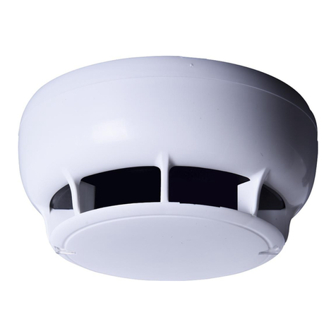
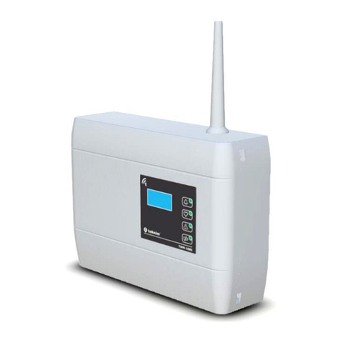
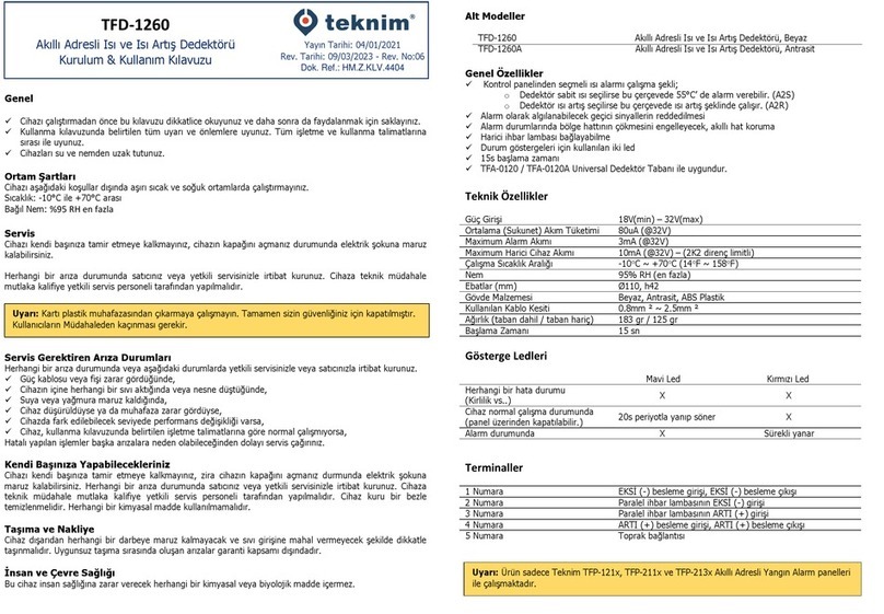
Teknim TFD-1271 Instruction Manual

TFD-1271
INTELLIGENT ADDRESSABLE MULTI DETECTOR
(OPTICAL SMOKE AND HEAT) WITH BUILT-IN ISOLATOR
(Multisensor)
Installation & User Manual
Yayın Tarihi: 27/07/2018
Rev:03
Release Date: 04/01/2020
Rev:01
Critical Warnings
General
✓Read this manual with care before operating the device and keep it for further reference.
✓Comply with all warnings and measures provided in the manual. Follow all respective operation and usage
instructions.
✓Keep the devices away from water and humidity.
Ambient Conditions
Do not operate the device under extreme temperature conditions that fall outside the following values.
Temperature: Between -10°C and +55°C
Relative Humidity: Max. 95% RH
Service
Do not attempt to repair the device on your own, you may be exposed to electric shock in case you open the
device housing.
Contact your dealer or authorized service in case of a failure. Technical interventions to the device must be
carried out by qualified personel of authorized service.
Failures That Require Service Intervention
Contact your authorized service or dealer in case of a failure or in following cases.
✓If the power line or plug is damaged,
✓If any liquid has leaked or a substance has fallen into the device,
✓If the device is exposed to water or rain,
✓If the device is dropped or the housing is damaged,
✓If there is significant performance change in the device,
✓If the device is not operating normally according to the operating instructions in the user manual
Call the service since erroneous operations may cause further failures.
What You Can Do On Your Own
Do not attempt to repair the device on your own since you may be exposed to electric shock in case you
open the device housing. Contact your dealer or authorized service in case of a failure. Technical
interventions to the device must be carried out by qualified personel of authorized service. The device must
be cleaned with a dry cloth. No chemical must be used for cleaning purposes.
Handling and Transportation
The device must be handled with care in manner that it does not get exposed to impacts and liquid influx.
The damages that may occur during improper handling are out of guarantee.
Human and Environment Health
This device does not contain any chemical or biological substance that may harm human health.
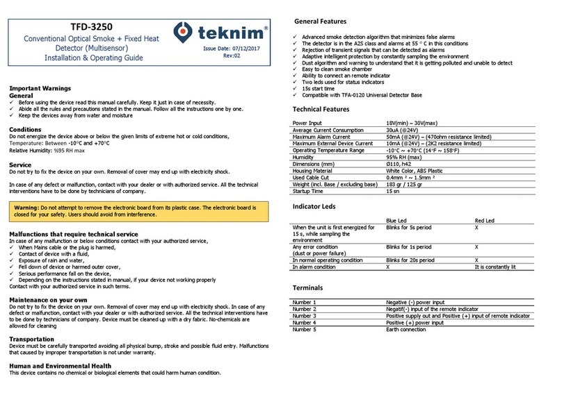
General Features
✓Advanced smoke detection algorithm that minimizes false alarms
✓The alarm can be produced at 55°C within this frame if Detector fixed heat is selected.(A2S)
✓Denial of temporary signals that may be perceived as alarm
✓Adaptive protection by continuous sampling of the present environment
✓Debris algorithm that perceives inoperability due to dirt accumulation and respective warning
✓Easy to clean smoke chamber
✓External notification light connection means
✓Two LED’s used for state indication purposes
✓15s starting time
✓Three different sensitivity settings that can be selected on the panel
✓Operation logic with and/or that can be adjusted on the panel
✓Possibility to operate solely as heat or solely as smoke detector that can be adjusted on the panel
✓Compatible with TFA-0120 Universal Detector Base
Technical Specifications
Power Input
18V(min) –32V(max)
Average (Quiescent) Current Consumption
80uA (@32V)
Maximum Alarm Current
3mA (@32V)
Maximum External Device Current
10mA (@32V) –(2K2 resistance limit)
Alarm Levels (appr.)
H: 0.12, M: 0.15, L: 0.18 dB/m
Operating Temperature Range
-10C ~ 55C (14F ~ 131F)
Humidity
95% RH (max.)
Size (mm)
Ø110, h42
Housing Material
White Color, ABS Plastic
Attached Cable Cross-section
0.4mm ² ~ 1.5mm ²
Weight (wit base / without base)
183 gr / 125 gr
Starting Time
15 sec
Isolator
Average Current Consumption (Normal Op.) @24V
15uA
Vmax.
32V
Vnom.
28V
Vmin.
15V
Vso_max.
18V
Vso_min.
9V
Vsc_max.
5V
Vsc_min.
0,7V
Ic_max.
0,5A
Is_max.
3A
IL_max.
0,026A
Zc_max.
0,026Ω
Warning: Do not attempt to take the card out of its plastic protection. It is sealed solely for your safety.
Users must avoid intervention.

Indicator LED’s
Blue Led
Red Led
Yellow Led
Any error situation
(Pollution etc..)
Blinks with 4 sec. intervals
X
X
The device is in normal
operation mode
(can be turned off.)
Blinks with 20 sec. intervals
X
X
Alarm state
X
Constant
X
Short circuit state
X
X
Constant
Terminals
No. 1
NEG.(-) supply input
No. 2
NEG.(-) supply output, NEG. (-) input of parallel notification light
No. 3
POS. (+) input of parallel notification light
No. 4
POS.(+) supply input, POS.(+) supply output
No. 5
Earth connection
Installation and Connection
1. Turn (1) the detector head counterclockwise to the short line and pull (2) it up to disassemble from the
base.
2. Mount the base part by using the mounting place shown (2).
3. Make the cable connections according to the following diagram. Make the connection by observing that
the polarity of Leg No. 4 is (+) and Leg No. 1 is (–), and then by connecting (-) pole from No 2 and (+)
pole from No. 4 of the current detector to No.1 of the next detector.
4. Use the connections No. 3(+) and 2(-) for the parallel notification light.
5. Install the detector head into its place. Make sure that the line on the head piece is aligned with the long
line on the base.
6. Energize the detector. The LED on the detector will blink blue light once in every 20 seconds in the state
without an alarm in order to indicate that the device is in operation. (This feature may be turned off from
the panel)
7. Make the chasis(earth) connection of the cable continuously over the Leg No. 5 between the loop output
and the last detector.
Test
Observable smoke flow must be provided in order to obtain correct results. In order to perform a smoke test,
ensure that the smoke goes into the smoke detection chamber min. for 1 minute by using a burning material
or test spray. The LED lights and indicates the alarm when sufficient amount of smoke enters into the
chamber.
1. Fend of the smoke source when the device goes into the alarm state.
2. Check to see whether the red LED’s light continuously. Reset the detector from the panel.
3. The detector must be sent to the service if it does not produce alarm within 1 minute.
4. The system may be activated after the test is performed.
Heat Testi:
Providing an air flow of appr. 70°C is sufficient for the detector test.
1. Start the hot air flow and check the temperature.
2. Apply the hot air into the detector. The detector must produce the alarm within 30 seconds.
3. Check to see whether the red LED’s light continuously. Reset the detector from the panel.
4. The system may be activated after the test is performed.
Warning: The product operates only with Teknim TFP-121x, TFP-122x ve TFP-123x Intelligent Addressable
Fire Alarm panels.
Loop Connection
Connector
Parallel Notification Light
(TFA-1196)
A: Head
B: LED’s
C: Base

1922
Bilgi Elektronik San. ve Tic. A.Ş.
Dudullu OSB 1. Cad. İsmet Tarman İş Merkezi
No:1 Kat:2 No:32 Ümraniye / İstanbul
20
1922-CPR-1459
EN 54-7:2000; EN 54-7:2000/A1:2002; EN 54-7:2000/A2:2006
Point smoke detectors (Scattered Light)
EN 54-5:2000; EN 54-5:2000/A1:2002
Point heat detectors
Class A2S
EN 54-17:2005
Fire Detection and Fire Alarm Systems –Short Circuit Isolators
TFD-1271
Technical data: See BİLGİ-TEC-171128-1 kept by the
manufacturer.
Manufacturer Company and Main Service
* In compliance with AEEE regulations. This product is manufactured from recyclable and reusable high
quality parts and materials. Therefore, do not dispose of the product together with domestic or other wastes
at the end of its service lifetime. Take it to a drop-off point for the recycling of electrical and electronic
devices.
* The consumer may apply to the Consumer Arbitration Board or Consumer Court of the place of residance or
of the consumer transactions in case of disputes arising from exercising the rights granted by the guarantee.
Bilgi Elektronik San. ve Tic. A.Ş.
Dudullu Organize Sanayi Bölgesi 1. Cadde İsmet Tarman İş Merkezi
No:1 Kat:2 No:32 Ümraniye / İstanbul / Turkey
Phone: +90 216 455 88 46 Facsimile: +90 216 455 99 06
www.bilgielektronik.com.tr
satis@bilgielektronik.com.tr
destek@bilgielektronik.com.tr
Other Teknim Security Sensor manuals

Teknim
Teknim TVSD143 User manual

Teknim
Teknim ATP545 User manual

Teknim
Teknim TWD-1850 Instruction Manual

Teknim
Teknim TFD-3240 Troubleshooting guide

Teknim
Teknim TWM-3885 Instruction Manual

Teknim
Teknim TSD-5150 User manual

Teknim
Teknim TFD-1260 Instruction Manual

Teknim
Teknim TWD-1850 Instruction Manual

Teknim
Teknim TFD-3250 Troubleshooting guide

Teknim
Teknim TFD-1260A Instruction Manual