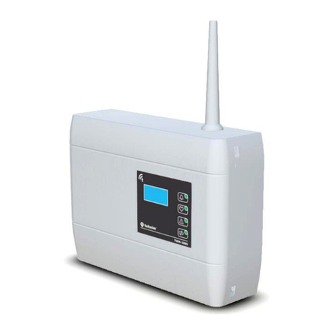
Teknim TWM-1885 Instruction Manual

TWM-1885
Analogue Addressed Wireless Coordinator
Installation & User Manual
Release Date: 15/09/2021 Rev:01

TWM-1885 ANALOGUE ADDRESSED WIRELESS COORDINATOR –R01
1
Contents
1 General Definitions.......................................................................................................................... 2
2 Technical Specifications................................................................................................................... 2
3 Installation....................................................................................................................................... 3
3.1 Mounting................................................................................................................................. 3
3.1.1 Cable Holes...................................................................................................................... 3
3.1.2 Wall Mounting................................................................................................................. 4
3.2 Antenna Installation ................................................................................................................ 4
3.3 Network Cable Connection...................................................................................................... 5
3.4 Relay Cable Connection........................................................................................................... 6
3.5 Module Interface..................................................................................................................... 7
3.6 Programming Menu ................................................................................................................ 7
3.6.1 Events .............................................................................................................................. 8
3.6.2 Settings............................................................................................................................ 9
3.6.3 Functions ....................................................................................................................... 11
3.6.4 Device List...................................................................................................................... 14
3.6.5 Information.................................................................................................................... 15
4 Ping Time....................................................................................................................................... 17
5 Quick Menu Access........................................................................................................................ 18
6 Events and Indicators .................................................................................................................... 19
7 Signal Strength Table (RSSI Table)................................................................................................. 20
8 Quick Installation........................................................................................................................... 20
9 Software Update ........................................................................................................................... 20
10 Manufacturer Company and Service......................................................................................... 21

TWM-1885 ANALOGUE ADDRESSED WIRELESS COORDINATOR –R01
2
1General Definitions
TWM-1885 Addressed Wireless Coordinator module, is the wired/wireless Access control unit that
provides the integration of TLPWAN(1) wireless system into FLASHLINK (2) analogue addressed fire alarm
network line. Basically, it enables TLPWAN-based wireless fire detection devices to be integrated into
the analogue addressed fire alarm system, just like the analogue addressed fire detection devices, and
to be monitored and controlled against fault and fire situations.
As in other network devices, TWM-1885 Addressed Wireless Coordinator module is fed through the
network line without the need for an external power supply and communicates with the analogue
addressed fire alarm panel through FLASHLINK protocol. With a simple definition, it serves as
FLASHLINK-TLPWAN protocol converter.
(1) TLPWAN (Teknim Low Power Wide Area Network) is a wireless communication protocol developed
by Teknim which allows low power consumption devices on a wider area in a stable and safe manner
by using two-way communication.
(2) FLASHLINK, is an uninterrupted and safe communication protocol developed by Teknim which allows
the data communication between the network card and terminals through power line.
2Technical Specifications
Network Supply Voltage
18Vdc –35Vdc
Average Current Consumption
10mA (@24Vdc)
Operating Frequency
868 MHz
Output Power
14 dBm (25 mW)
Communication Distance
500 m (open area)
Number of Channels
10
Total number of connectible devices
31 (Routers and other devices)
Number of Routers That Can be Connected Consecutively
5
Number of Routers That Can be Connected to a
Coordinator Side-by-Side
5
Humidity
95% RH
Operating Temperature
-10 –+55°C
Size (mm)
150 mm x 110 mm x 42 mm + 70 mm Antenna
Housing Material
White Color, ABS Plastic
Cross-section of the Cable Used
0.4mm ² ~ 1.5mm ²
Weight
185 gr

TWM-1885 ANALOGUE ADDRESSED WIRELESS COORDINATOR –R01
3
3Installation
Under this topic, the installation of TWM-1885 Addressed Wireless Coordinator module will be
explained step by step in details. Please read all steps carefully.
3.1 Mounting
The following articles must be followed carefully in order to provide a good communication with the
devices connected to the coordinator:
•Choosing a proper communication channel will make the communication between the devices
more stable. Channel selection can be made automatically or manually. If manual selection is
to be made, initially all transmissions in the environment must be detected with the RF-
analyzer and according to this, relatively the most available channel must be preferred. See
programming section for manual channel selection.
•The environmental factors such as high current lines, big metal objects, computers, network
lines, other cable lines, etc. that may interrupt the connection with the devices on the wireless
network must be avoided.
•There must be at least 2 meters of distance from other wireless devices.
•If possible, it must be mounted at least 2 meters high from and parallelly to the ground. The
antenna must remain at an angle of 90 degrees to the ground.
•It must be operated under the proper ambient conditions indicated in technical specifications.
Otherwise, the operating performance will be affected.
•A suitable location must be preferred by considering the communication distance when all
devices to be communicated are taken into consideration. Communication distance can be
seen in technical specifications.
The mounting holes of the module are located under the module cover. In order to access those, the
cover must be opened by gently pushing through the holes on the right side of the module by using a
flathead screwdriver.
3.1.1 Cable Holes
The holes through which the cables necessary for module connection will pass must be prepared
before wall mounting. For this purpose, holes must be broken open on the round points marked on
the product housing. Before breaking open the holes, the cards inside of the module must be removed.
The tabs holding the cards must be pulled gently in order to remove the cards.
TWM-1885 ANALOGUE ADDRESSED WIRELESS COORDINATOR –R01
4
Once the cards are removed, a gentle pressure must be applied behind the point to be broken open in
a manner to leave a space underneath by using a thick screwdriver in order to break open the holes.
The cards can be reinstalled and fixed after this procedure.
3.1.2 Wall Mounting
Mark the wall according to the 4 screw holes seen below and bore 4 holes on the wall by using a drill
according to the diameters of the wall plugs included in the pack. Insert the wall plugs into the bored
holes and fix the module on the wall by screwing it onto the wall.
Figure 1 –Mounting Hole Sizes
3.2 Antenna Installation
TWM-1885 Addressed Wireless Coordinator module is placed in the box with the antenna wire and
antenna housing disassembled. Ensure a good installation of the antenna in order to provide a good
communication between devices. Otherwise, there may be distance problems and communication
performance losses.
There are two superposed cards connected to each other in the module: The upper one of those is
TLPWAN-RF card, while the other serves as the Flashlink interface and control card. The antenna
terminal is located on the TLPWAN-RF positioned as the lower card. Pass the wire antenna through the
antenna input of the box and fix it on the terminal to the right as shown in the figure. Make sure that
the terminal screw is firmly tightened. An antenna that is not fixed properly may cause performance
loss.

TWM-1885 ANALOGUE ADDRESSED WIRELESS COORDINATOR –R01
5
Figure 2 –Antenna Wire Installation
Once the wire antenna is fixed into its place, push the antenna housing into the antenna input tightly
to fix it into its place.
Figure 3 –Antenna Housing Installation
3.3 Network Cable Connection
Pass the cables through the cable holes and strip their ends at a proper length, then make the in and
out connections as shown in the following connection diagram. Make sure that the terminal screws
are tightened firmly.

TWM-1885 ANALOGUE ADDRESSED WIRELESS COORDINATOR –R01
6
Figure 4 –Network Connection Diagram
3.4 Relay Cable Connection
Addressed Wireless Coordinator module has the activation feature just like the addressed in-out
modules. The conditions during which the relay on the Addressed Wireless Coordinator module will be
active/passive can be determined by selecting the output activation feature on the analogue
addressed fire alarm panel. The output activation type can be selected as “General Alarm, General
Siren, General Fault, Zone Alarm, Zone Siren, Zone Fault”.
Make the relay connection as shown in the following connection diagram is the output activation
feature will be used.
Figure 5 –Relay Connection Diagram
Normally Closed
Common End
Normally Open
LOOP IN+
LOOP IN-
LOOP OUT-
LOOP OUT+

TWM-1885 ANALOGUE ADDRESSED WIRELESS COORDINATOR –R01
7
3.5 Module Interface
Figure 6 –Module Card Detailed Interface
•Network Connection: It is used for connection to analogue addressed panel network line.
•Relay Connection: It is used for the output activation feature adjusted on the analogue
addressed panel.
•Serial Port: It is used for software update.
•USB: It is used for monitoring and analysis programs.
•Tamper Button: It is used for detecting that the cover is opened. When the cover is opened,
this will be shown as a fault on the analogue addressed fire alarm panel.
•OLED Screen: The screen will not work in quiescent state. It will be activated in case of any
alarm, fault state or when the cover is opened. Programming menu can be accessed on this
screen.
•Alarm Led: It shows any alarm state on the wireless system.
•Heart Led: It shows that the module is operating and the wireless network is set.
•Fault Led: It shows any fault state on the system.
•Low Battery Led: It lights when the battery of any wireless devices is low.
•L1 Led: It lights when connection to wireless network is activated.
•L2 Led: It lights when there is an ongoing process.
•BACK Button: It is used for going back on the menu or for cancelling.
•DOWN Button: It is used for proceeding on the menu or for decreasing a value on the menu.
•UP Button: It is used for going back on the menu or for increasing a value on the menu.
•FORWARD Button: It is used for going to a menu that is selected on the menu or for approval
purposes.
3.6 Programming Menu
Addressed Wireless Coordinator module menu will be explained under this topic.
BACK Button
DOWN Button
FORWARD Button
UP Button
OLED Screen
L5 –Heart Led
L6 –Low Battery Led
L1 Led
L2 Led
L4 - Heart Led
L3 - Alarm Led
Tamper Button
USB
Serial Port
Relay Connection
Network Connection

TWM-1885 ANALOGUE ADDRESSED WIRELESS COORDINATOR –R01
8
If there are no events on the system when the menu is opened or the upmost menu is selected by
using the BACK button, the following main screen will be displayed initially:
FORWARD for the Menu
3.6.1 Events
This is the section under which the instant events that occur within the wireless system are listed. The
events are listed under three categories being “Alarm”, “Fault”and “Warning”.
Events
To enter the menu: “Main Screen” > FORWARD > “Events” > FORWARD
Events
>1.Alarm
2.Fault
3.Warning
Any category can be selected from the “Events” screen shown above, and the devices under the
selected category are listed. Example: “Fault” category is selected in the following figure and the
devices in fault state are listed.
Fault (2)
>1.Coordinator
ID:18850601200001
2.Detector
ID:18502001200015
To navigate through the device list, use the DOWN and UP buttons on the menu. Go to sub-menu by
pressing the FORWARD button in order to read the details of faults. Example: Coordinator is selected
and its fault detail is displayed. On the address line, the number in brackets is the address in the
addressed system and then the address in the wireless system. On the following lines, the fault states
of the respectively selected devices are listed. If there are more than one fault states, they will be listed
one under the other.

TWM-1885 ANALOGUE ADDRESSED WIRELESS COORDINATOR –R01
9
18850601200001
>1.Address: (1)0
2.Tamper Active
3.6.2 Settings
This is the menu which device address, number of devices, channel, language and screen contrast
settings can be adjusted.
Settings
To enter the menu: “Main screen” > FORWARD > DOWN > “Settings” > FORWARD
Settings
>1.Addressing
2.Number of Devices
3.Channel
4.Language
5.Contrast
3.6.2.1 Addressing
The address range within which the Addressed Wireless Coordinator module will be displayed on the
Analogue Addressed Panel is determined with the “Addressing” setting. To enter the addressing
screen, navigate through the settings menu by using UP and DOWN buttons and select the
“Addressing” menu.
Use the UP and DOWN buttons to change the address value by increasing or decreasing the value.
Press FORWARD button to approve and see the “Successful” inscription on the screen. Press BACK
button to exit from the menu or to cancel the changed value. Address value cannot be selected higher
than 225.
Addressing
Address 10
1:225 range
As explained in the technical specifications section, “31” devices can be connected to the Addressed
Wireless Coordinator module. A wireless system, together with the Addressed Wireless Coordinator
module, covers a total address area of "32" the most. Example: The address value selected as "10"

TWM-1885 ANALOGUE ADDRESSED WIRELESS COORDINATOR –R01
10
above will allow new devices to be added between 10 and 41 in the Addressed Fire Alarm panel in a
situation that "31" wireless devices are added to the system. (The number of devices was selected as
32)
3.6.2.2 Number of Devices
Number of devices is a value being used together with the addressing value. It determines how many
devices can be added after the address selected from the “Addressing” menu on the Addressed Fire
Alarm panel. Select the “Number of Devices” menu by navigating on the settings menu by using UP
and DOWN buttons.
To change the number of devices, increase or decrease the value by using UP and DOWN buttons.
Press FORWARD button to approve and see the “Successful” inscription on the screen. Press BACK
button to exit from the menu or to cancel the changed value. Number of devices can be selected “32”
the most.
Number of Devices
Number 16
1:32 range
Example: The number of devices selected as “16” in the above figure, allows new devices to be added
within the address range of 10 and 25 on the Addressed Fire Alarm panel. (Addressing value is selected
as 10) Even if “31” devices are added in the wireless system, if the number of devices is selected as
“16”, then only the first 16 devices can be listed on the fire alarm panel.
3.6.2.3 Channel
Each small frequency range obtained by dividing the frequency range reserved for TLPWAN into 10
segments, corresponds to one channel. Each wireless system having its own independent channel
allows the wireless systems to communicate in the same environment without any data interference.
On the channel screen, the channel that a new wireless system (PAN) to be established will
communicate through can be selected. As indicated in technical specifications section, TLPWAN
wireless systems can communicate through “10” channels. To enter the Channel screen, navigate
through the settings menu by using UP and DOWN buttons and select “Channel” menu.
To change the channel value increase or decrease the value by using UP and DOWN buttons. Press
FORWARD button to approve and see the “Successful” inscription on the screen. Press BACK button
to exit from the menu or to cancel the changed value. Address value can be selected as 10 the most.
“0” value allows the most available channel from the RF direction to be determined and automatically
selected.
Channel
Channel 0
0: Automatic
1-10: Fixed

TWM-1885 ANALOGUE ADDRESSED WIRELESS COORDINATOR –R01
11
Example: The channel value selected as “0” above, provides all channels to be scanned during the
wireless system setup and allows the most available channel to be selected automatically.
3.6.2.4 Language
The language of the Addressed Wireless Coordinator module can be changed with this setting. To enter
the Language screen, navigate through the settings menu by using UP and DOWN buttons and select
“Language” menu.
To change the language, navigate through the language options by using UP and DOWN buttons. Press
FORWARD button to approve and see the “Successful” inscription on the screen. Press BACK button
to exit from the menu or to cancel the changed value.
Language
Language English
3.6.2.5 Contrast
The screen contrast value can be changed with this menu. To enter the Contrast screen, navigate
through the settings menu by using UP and DOWN buttons and select “Contrast” menu.
To change the contrast value, increase or decrease the value by using UP and DOWN buttons. Press
FORWARD button to approve and see the “Successful” inscription on the screen. Press BACK button
to exit from the menu or to cancel the changed value. The contrast value can be selected within the
range of 0-255. Decreasing the contrast value will reduce the OLED screen’s current consumption.
Contrast
Contrast 100
3.6.3 Functions
Functions menu allows the settings such as wireless system setup, reset, connection permission to be
made.
Functions
To enter the menu: “Main screen” > FORWARD > DOWN > “Functions” > FORWARD

TWM-1885 ANALOGUE ADDRESSED WIRELESS COORDINATOR –R01
12
Functions
>1. Setup PAN
2. Delete PAN!!
3. Connection Permission
4. Reset PER
3.6.3.1 Setup PAN
Setting up a new wireless system can be made from this menu. PAN is an abbreviation used in the
network terminology and it stands for Personal Area Network.
A wireless system (PAN) is initially needed for the wireless devices to be connected to a network. If
there is a network set, the “Heart Led” blinks. If no network is set, the “Heart Led” is off. Thus, the
“Heart Led”can be used as the indicator of a set network.
To enter the Setup PAN screen, navigate through the functions menu by using UP and DOWN buttons
and select “Setup PAN” menu.
To setup PAN, select “Yes” or “No” by using UP or DOWN buttons and press FORWARD button to
complete the operation. This operation may take some time, therefore the warning “Waiting..” will be
shown on the screen. Once the PAN Setup operation is completed, the warning “Successful” will be
displayed on the screen and this warning will disappear after 2 seconds. The result of the PAN setup
operation can be verified by checking the “Heart Led”. The screenshots of this operation can be seen
below.
Setup PAN
Setup PAN Yes
Setup PAN
Setup PAN Yes
Setup PAN
Setup PAN Yes
Once the PAN setup operation is completed, the wireless devices can now be connected to the newly
established wireless network. The PAN connection permission must be activated for the devices to be
connected to the newly established PAN.
3.6.3.2 Delete PAN!!
A previously established PAN (Wireless Network) can be deleted from this menu. PAN deletion
operation does not affect other wireless networks, but only deletes the devices connected to it and
the settings and gets prepared for a new PAN to be set.
To enter the PAN deletion screen, navigate through the functions menu by using UP and DOWN
buttons and select “Delete PAN!!” menu.
To delete PAN, select “Yes” or “No” by using UP or DOWN buttons and press FORWARD button to
complete the operation. This operation may take some time, therefore the warning “Waiting..” will be
shown on the screen. Once the Delete PAN operation is completed, the warning “Successful” will be
displayed on the screen and this warning will disappear after 2 seconds. The result of the Delete PAN
operation can be verified by checking the “Heart Led”. The screenshots of this operation can be seen
below.
Waiting..
Successful

TWM-1885 ANALOGUE ADDRESSED WIRELESS COORDINATOR –R01
13
Delete PAN
Delete PAN Yes
All devices
will be deleted!
Delete PAN
Delete PAN Yes
All devices
will be deleted!
Delete PAN
Delete PAN Yes
All devices
will be deleted!
3.6.3.3 Connection Permission
The connection permission must be activated on the wireless network initially for a wireless device to
connect to the wireless network. This permission operation can be carried out from “Connection
Permission” menu. To enter the connection permission screen, navigate through the functions menu
by using UP and DOWN buttons and select “Connection Permission” menu.
Increase or decrease the value by using UP and DOWN buttons for changing the connection
permission. Press FORWARD button to approve and see the “Successful” inscription on the screen.
Press BACK button to exit from the menu or to cancel the changed value.
Connection Permission
Permission 255
0:Off
1-254:On for seconds set
255:On unlimitedly
Connection permission can be adjusted with or without time limit. The value within “1-254” range will
determine for how many seconds the connection permission will be on. This period restarts after each
new connection operation and allows device connection without the need for the user to activate
connection permission over and over again. However, the value “255” provides the connection
permission to be on for an indefinite period of time. The value “0” must be chosen to turn off the
connection permission again. Activating the connection permission with a time limit can be considered
as a measure taken against the connection permission to be left on without time limit.
“L1” led lights continuously as long as the connection permission is on.
3.6.3.4 Reset PER
PER is an abbreviation being used in the communication technology. It stands for Packet Error Ratio. It
indicates the ratio of the number of erroneous packets sent by the device from the beginning to the
total number of packets sent.
PER values play a role as an important indicator in order to understand the healthy operation of the
wireless system. PER values of devices may increase at the system setup phase due to reasons such as
attaching, detaching, energy, etc. Therefore, in some cases, PER values may need to be reset. To enter
Reset PER screen, navigate through the functions menu by using UP and DOWN buttons and select
“Reset PER” menu.
Waiting..
Successful

TWM-1885 ANALOGUE ADDRESSED WIRELESS COORDINATOR –R01
14
Select “Yes” or “No” by using by using UP and DOWN buttons for resetting the PER values of all devices
and the operation is carried out by pressing FORWARD button. The screenshots of this operation can
be seen below.
Reset PER
Reset Yes
Reset PER
Reset Yes
Reset PER
Reset Yes
3.6.4 Device List
The list of the devices connected to the wireless network can be accessed from this menu. Address
values, RSSI value, battery status, number of successfuland unsuccessful data transmissions and device
deletion operations are carried out on the “Device Detail” screen under “Device List”.
Device List
To enter the menu: “Main screen” > FORWARD > DOWN > “Device List” > FORWARD
Device List
1.Coordinator*
ID:18850601200001
>2.GC Module
ID:18871702200013
To navigate through the device list, use the DOWN and UP buttons. Press FORWARD button and move
towards the sub-menu in order to view device details.
18871702200013
>1.Address:(2)24966
2.RSSI: -23dB
3.Battery: 98%
4.PER: <2%
5.HW: 1.0.0
18871702200013
5.HW: 1.0.0
6.SW: 1.0.0
7.Ping: 20s
8. Reset PER
>9. Delete
Example: GC Module is selected and the device detail is viewed.
Device Details Screen:
1. The device’s address in the addressed system and in the wireless system
2. RSSI value. RSSI, is an abbreviation being used in RF terminology. It stands for Received Signal
Strength Indicator. It is a measurement value of the current power of the radio signal received
Waiting..
Successful

TWM-1885 ANALOGUE ADDRESSED WIRELESS COORDINATOR –R01
15
by the device. This value is directly related to the distance between the receiver and the
transmitter as well as to other environmental factors. Refer to the “Signal Strength” table for
RSSI value ranges.
3. Battery status is scaled between 0 and 100. “Battery Low” warning will be generated for the
devices having a battery status less than 25%.
4. PER is an abbreviation being used in the communication terminology. It stands for Packet Error
Ratio. It indicates the ratio of the number of erroneous packets sent by the device from the
beginning to the total number of packets sent. Distance and environmental factors are the
mains reasons of data transmission failures. Initially the RSSI values are checked on the devices
having high PER values. In case the RSSI values are within normal limits the device is removed
from its place and taken to a point that is close to the coordinator and the change in PER value
is observed. Device battery is taken out and installed back again after a while for resetting the
PER value or it can be reset by using the “Reset PER” option from the device menu. If the PER
value still continues to increase the RF intensity in the environment must be checked. In such
case, the PAN might have been setup on a wrong channel or other PANs may be taking too
much space on this channel.
5. HW indicates the hardware version.
6. SW indicates the software version.
7. Ping time, indicates the frequency that the devices will communicate with the connected
coordinator/router. A shorter ping time means that the coordinator will communicate with
the device faster and that reduces battery life. In order to adjust ping time, press FORWARD
on the menu selected to proceed to the ping time adjustment page. More detailed information
about ping time can be found under “Ping Time” topic.
8. Reset PER is used for resetting the PER value of the device selected. Menu usage is explained
under the “Reset PER” topic under the functions. When this menu is accessed from the device
selected, the PER value of only the selected device will be reset.
9. “Delete” is selected for deleting this device from the wireless network and the operation is
approved by pressing the FORWARD button. The inscription “Successful” will be displayed on
the screen if the operation is successful while “Unsuccessful” will be displayed otherwise. The
place of the deleted device will be shown blank on the list. The deleted device cannot send
data to the coordinator anymore. It needs to be connected back again.
3.6.5 Information
Module software and hardware versions, PAN details are viewed under this screen.
Information
To enter the menu: “Main screen” > FORWARD > DOWN > “Information” > FORWARD

TWM-1885 ANALOGUE ADDRESSED WIRELESS COORDINATOR –R01
16
Information
>1.16 Device
2.4 Router
3.HW: 1.0.0
4.SW: 1.0.0
5.PAN Set
Information
4.SW: 1.0.0
5.PAN Set
6.Channel: 4
7.PAN ID: 10
>8.TX Power: 14dBm
Information Detail Screen:
1. Number of battery-operated devices in the wireless system.
2. Total number of coordinator and routers.
3. Hardware version of the module card.
4. Software version of the module card.
5. If PAN is set, the inscription is “PAN Set”; if PAN is not set the inscription is “No PAN”.
6. Indicated the channel on which the PAN is set.
7. Each PAN has its own PAN ID. This value is selected randomly during the PAN setup operation
between “1-65535” as a unique number. If more than one PAN is required to be set on the
same channel, the PAN ID provides the data traffic between the PANs run uninterruptedly. In
other words, PAN ID is an identity number that indicates the PAN which should receive the
data transmitted within a wireless system.
8. Tx Power is the power value of the radio signals transmitted from the RF circuit in “dBm”.

TWM-1885 ANALOGUE ADDRESSED WIRELESS COORDINATOR –R01
17
4Ping Time
Ping time, indicates the frequency that the devices will communicate with the connected coordinator
or router. A shorter ping time means that the coordinator will communicate with the device faster and
that reduces battery life.
Example: A wireless siren having a ping time of 30 seconds will receive and operate the sound
command in 30 seconds.
Ping times of devices:
Device Type
Adjustable Ping Time
Default Ping Time
Multi-detector
120s
120s
Fire Button
120s
120s
Input/Output Module
10-120s
20s
Siren/Flasher
10-120s
10s
Ping times and battery life relations of devices:
Device Type
Ping Time / Battery Life
10s
20s
60s
120s
Multi-detector
-
-
-
8 years
Fire Button
-
-
-
10 years
Input/Output Module
3 years
5 years
8 years
10 years
Siren/Flasher
3 years
5 years
8 years
10 years
Maximum 10 sirens/flashers or input/output modules can be connected to one PAN!
In order to adjust the ping time, initially select a device from the device list and select “Ping:xxs” from
the device menu and press FORWARD button to proceed to the ping adjustment page.
18871702200013
5.HW: 1.0.0
6.SW: 1.0.0
>7.Ping: 20s
8. Reset PER
9. Delete
Ping
Ping 20
10-120 seconds
Increase or decrease the value by using UP and DOWN buttons for changing the ping time. Press
FORWARD button to approve and see the “Successful” inscription on the screen. Press BACK button
to exit from the menu or to cancel the changed value.

TWM-1885 ANALOGUE ADDRESSED WIRELESS COORDINATOR –R01
18
5Quick Menu Access
General structure of the module menu is shown in the following diagram.
Figure 7 –Quick Access Menu
Main Screen
Events
Fires
Device X
Address
Fire Type
..
Device Z
Faults Device A
Address
Fault 1
Fault 2
Fault..
Warnings
Settings
Addressing
Number of Devices
Channel
Language
Contrast
Functions
Setup PAN
Delete PAN!!
Connection
Permission
Reset PER
Device List
Device 1
Address
RSSI
Battery
PER
HW
SW
Ping: xxs
Reset PER
Delete
..
..
Device 32
Information
Number of Devices
Number of Routers
HW Version
SW Version
PAN Information
Fire
Fault

TWM-1885 ANALOGUE ADDRESSED WIRELESS COORDINATOR –R01
19
6Events and Indicators
The events about all devices on the wireless system and the manner of displaying such events are
shown in the following tables.
Wireless Detector
L3
L4
L5
L6
OLED
Smoke Alarm
Yes
-
-
-
Yes
Temperature Alarm
Yes
-
-
-
Yes
Pollution Alarm
-
-
Yes
-
Yes
Temperature Increase Alarm
Yes
-
-
-
Yes
Low Battery Alarm
-
-
Yes
Yes
Yes
Loss Fault
-
-
Yes
-
Yes
Tamper Fault
-
-
Yes
-
Yes
Wireless Fire Button
L3
L4
L5
L6
OLED
Button Alarm
Yes
-
-
-
Yes
Low Battery Error
-
-
Yes
Yes
Yes
Loss Fault
-
-
Yes
-
Yes
Tamper Fault
-
-
Yes
-
Yes
Wireless Input Output Module
L3
L4
L5
L6
OLED
Input Alarm
Yes
-
-
-
Yes
Input Open Circuit Fault
-
-
Yes
-
Yes
Input Short Circuit Fault
-
-
Yes
-
Yes
Output Active Warning
-
-
-
-
Yes
Low Battery Error
-
-
Yes
Yes
Yes
Loss Fault
-
-
Yes
-
Yes
Tamper fault
-
-
Yes
-
Yes
Wireless Siren
L3
L4
L5
L6
OLED
Low Battery Error
-
-
Yes
Yes
Yes
Loss Fault
-
-
Yes
-
Yes
Tamper Fault
-
-
Yes
-
Yes
Wireless Router
L3
L4
L5
L6
OLED
Loss Fault
-
-
Yes
-
Yes
Tamper Fault
-
-
Yes
-
Yes
Addressed Wireless Coordinator
L3
L4
L5
L6
OLED
PAN Set
-
Yes
-
-
-
RF Card Loss Fault
-
-
Yes
-
Yes
Tamper Fault
-
-
Yes
-
Yes
Other manuals for TWM-1885
1
Table of contents
Other Teknim Security Sensor manuals

Teknim
Teknim TVSD143 User manual

Teknim
Teknim TFD-1271 Instruction Manual

Teknim
Teknim TFD-1260 Instruction Manual

Teknim
Teknim TWD-1850 Instruction Manual

Teknim
Teknim TFD-1270A Instruction Manual

Teknim
Teknim TWD-1850 Instruction Manual

Teknim
Teknim TFD-3240 Troubleshooting guide

Teknim
Teknim TSD-5150 User manual

Teknim
Teknim TFD-1261 Instruction Manual

Teknim
Teknim TFD-3250 Troubleshooting guide