TekTone Tek-CARE160 User manual

Tek-CARE160 Operation and Installation Manual
Copyright©2001-2020 TekTone®Sound & Signal Mfg., Inc., All rights reserved.
No part of this publication may be copied without the express written permission of TekTone ®
Sound & Signal Mfg., Inc. The content of this manual is furnished for informational use only, is sub-
ject to change without notice, and should not be construed as a commitment by TekTone. TekTone
Sound & Signal Mfg., Inc. assumes no responsibility or liability for any errors or inaccuracies that
may appear in this documentation.
TekTone, the TekTone logo, Tek-ALERT, Tek-BRIDGE, Tek-CALL, Tek-CARE, Tek-CHECK-IN,
Tek-COM, Tek-ENTRY, Tek-GUARD, Tek-MICRO, Tek-MMARS, Tek-PAGING, Tek-SAFE and
Tek-STATUS are either registered trademarks or trademarks of TekTone®Sound & Signal Mfg., Inc.
in the United States and/or other countries. All other trademarks are the property of their respective
owners.
TekTone®Sound and Signal Mfg., Inc., 324 Industrial Park Road, Franklin, North Carolina 28734,
USA.

Table of Contents
Introduction and Overview 4
Product Overview 5
Installation 7
Types of Installation 7
The NC160 Central Equipment Module 10
Wiring Installation 14
Connect Stations 17
Connect NC415AV/NC404TS Master Stations 22
Connect Data Bus Wiring 24
Connect Audio Bus Wiring 24
Connect Master Bus Wiring 24
Networking Multiple NC160 CE Modules 24
Configuration Setup 26
Connect the LS450 Config Tool Programming Software 26
Using the Config Tool Programming Software 27
Configure an Autodetect Configuration 30
Configure a Custom System 38
Audio Adjustments 42
Using the Tek-CARE160 System 44
Placing and Resetting Calls 44
Using the NC415AV/NC404TS Master Station 44

Introduction and Overview
Introduction
Welcome to the installation manual for the Tek-CARE160 nurse call system. This system
is designed to be low cost, easy to install, and extremely reliable. This manual will walk
you through the installation and configuration process, and will cover system operation as
well as common troubleshooting steps.
If you have questions at any point during the installation process, contact our Technical
Support Department by email at teksupt@tektone.net or by phone at 800.327.8466 or
828.524.9967. Choose Option 3 for Technical Support.
Overview
The Tek-CARE160 system is a versatile system that can satisfy the needs of a wide range
of facilities. At its core, the Tek-CARE160 system is a four-wire nurse call system
designed for easy installation and years of trouble-free operation. The system is available
with a variety of call stations such as two-button pull-cord stations, 1/4" jack call cord sta-
tions, duty stations, dome lights, and more.
In addition to these items, the Tek-CARE160 system can be easily integrated with exist-
ing TekTone nurse call systems, nurse call systems manufactured by other companies, as
well as a wide variety of building systems such as fire alarm systems, security and access
control systems, and much more.
The Tek-CARE160 system may be used as either a standalone nurse call system using
NC415AV/NC404TS Master Stations, or it may be connected to another TekTone nurse
call system, such as the Tek-CARE400 or Tek-CARE400P5/Tek-CARE400P5+ over the
Tek-CARE Network. With the addition of the LS601 Tek-ALERT Integration Manager,
the Tek-CARE160 system is capable of communicating with many other types of building
systems, such as fire alarm and security systems. The LS601 Tek-ALERT Integration Man-
ager also allows the system to display and log various events from older analog TekTone
nurse call systems such as the Tek-CARE NC110, NC150, NC200, and 300/III systems.
4|IL1024 Tek-CARE160 Installation Manual Copyright ©TekTone Sound and Signal Mfg., Inc. All Rights Reserved

Product Overview
NC160 Central Equipment Module: The Tek-CARE160 sys-
tem's main component is the NC160 Central Equipment (CE) Mod-
ule. The CE module is designed to be stackable or rack mountable.
The NC160 CE Module can operate as a standalone system, or as
a module on a larger, integrated Tek-CARE nurse call system. The
NC160 CE Module provides connections for 64 room controllers,
and six NC415AV or ten NC404TS Master Stations. Multiple CE
modules may be networked together to create a larger system.
NC415AV Master Station: The NC415AV Master Station is a
touchscreen master station that is used to interact with the Tek-
CARE160 system. The NC415AV Master Station displays calls
from the Tek-CARE160 system and provides limited pro-
gramming and configuration ability for the Tek-CARE160 system.
The NC415AV uses a five-inch LCD touchscreen to provide aud-
ible and visual annunciation of system calls. The NC415AV may
be mounted using the IH415D desk stand or wall-mounted using
the IH415W wall-mount bracket.
NC404TS Master Station: The NC404TS Master Station is a
touchscreen master station that is used to interact with the Tek-
CARE160 system. The NC404TS Master Station can display
maps and calls from the Tek-CARE160 system and provides pro-
gramming and configuration ability for the Tek-CARE160 system.
The NC404TS uses a 22-inch LCD touchscreen to provide audible
and visual annunciation of system calls. The NC404TS may be
mounted using the CL231 bracket.
LI122/LI122BL Room Controller: The LI122-Series Room
Controller provides connections for six Tek-CARE160 stations
and one connection for the Tek-CARE160 data bus. In most
instances, the room controller is installed outside a room in the
same position as a traditional dome light. The two-conductor cable
is used to connect Tek-CARE160 stations to the LI122-Series
Room Controllers. The rear of the room controller contains a 14-
pin header. Pins 1-12 are used in pairs for station connections, and
pins 13 and 14 are used to connect the room controller to the Tek-
CARE160 data bus. The LI122 annunciates high priority calls
with red LEDs and low priority calls with white LEDs. The
LI122BL is identical to the LI122, but with blue LEDs for high pri-
ority calls and white LEDs for low priority calls.
PM120 Room Controller: The PM120 Room Controller
provides connection points for Tek-CARE160 stations without the
dome light LEDs found on the LI122-series room controllers. The
PM120 is designed to be installed out of sight.
Copyright ©TekTone Sound and Signal Mfg., Inc. All Rights Reserved IL1024 Tek-CARE160 Installation Manual |5
Introduction and Overview

Introduction and Overview
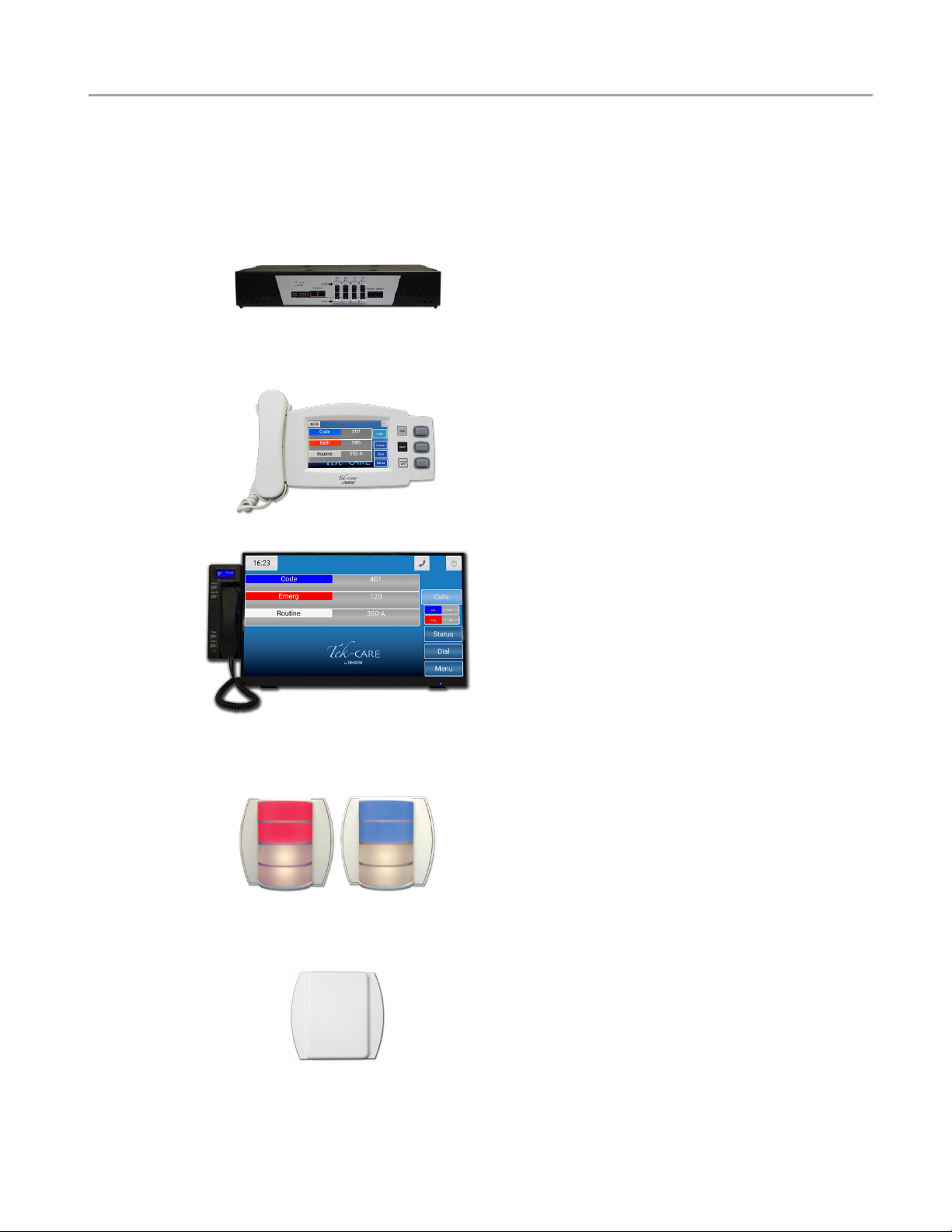
IR160 Audio Station: The IR160 Audio Station provides a
speaker and microphone for two-way communication between
facility staff and residents. The IR160 requires a connection to the
LI122 controller (using one point) and a connection to the Tek-
CARE160 Audio Bus cable. The IR160 Audio Station can be
installed as a standalone speaker, but is most commonly installed
with an SF121 or an SF123 series station in an IH122K dual
house gang housing. The IR160 shown to the left is shown with a
SF121 Patient Station.
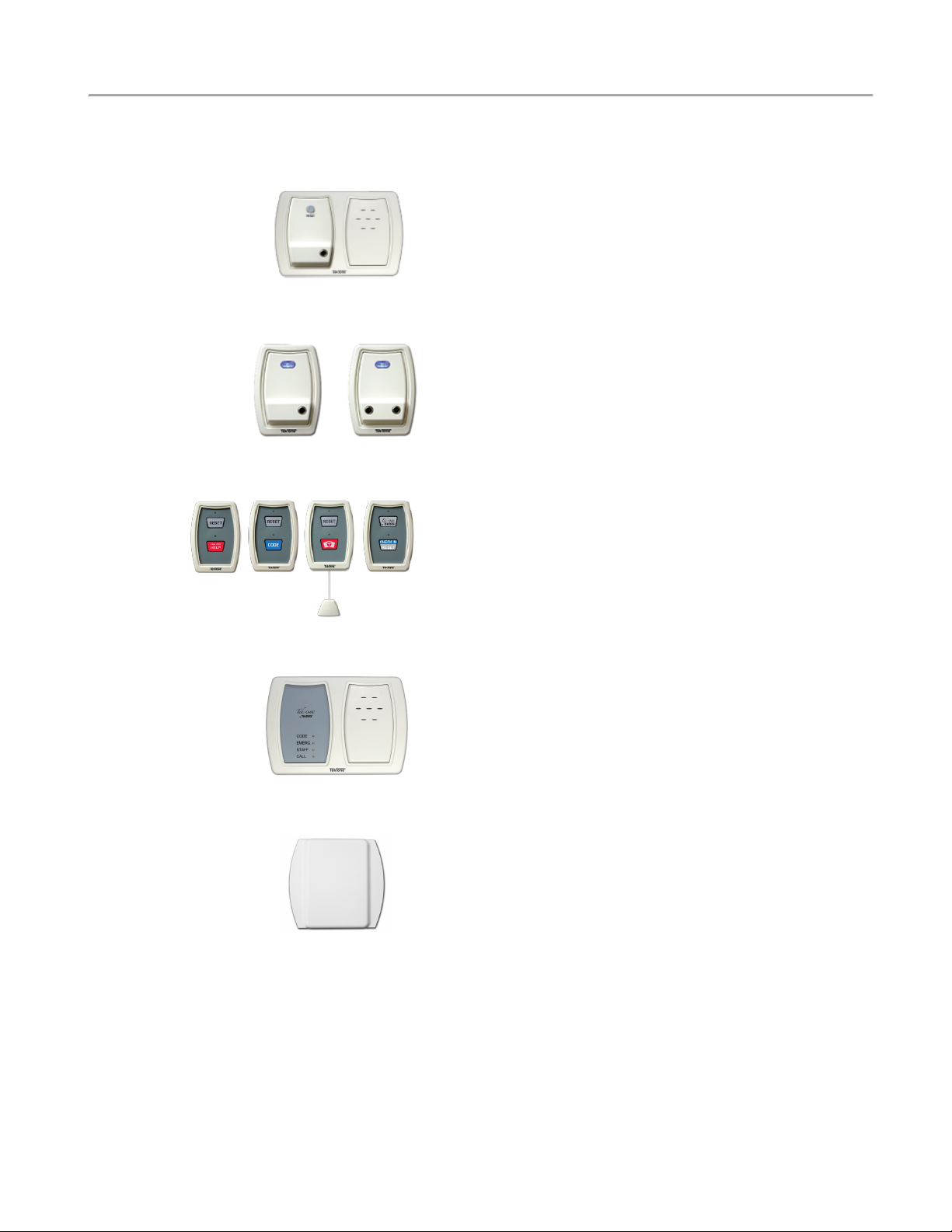
SF121 and SF122 Patient Stations: The SF121 Patient Station
is designed to provide a single 1/4" jack for standard call cords.
The SF121 mounts near a resident’s bed or chair, and enables calls
to be placed using pushbutton call cords, geriatric call cords, pneu-
matic call cords, and more. The SF121 is equipped with an illu-
minated reset button. The SF122 Patient Station is a dual-jack
version of the SF121.
SF123 2-Button Pull-Cord Station: The SF123 station is used
to place a variety of calls on the Tek-CARE160 system. The
SF123 uses interchangeable inserts depending on the desired func-
tion of the station. The SF123 is most commonly used as an Emer-
gency station, but can be easily configured for Bath, Code Blue,
and Emergency 2 calls. Custom call types may also be created, and
custom call type inserts can be generated using the LS450 Config
Tool software. The SF123 can also be used as a room-level reset
button and a check-in station. Use the RP187K Gasket Kit for
mounting in wet environments.
SF125 Duty Station: The SF125 is a duty station used to alert
staff to pending Tek-CARE160 system calls. The duty station is
installed in areas where call annunciation is needed, but the full
functionality of a master station is not. Four LEDs communicate
the type of active call, and an audible tone alerts staff members
when calls are placed. The SF125 duty station uses two points on
the LI122-series Room Controller or PM120 Room Controller.
PM123 Auxiliary Input Module: The PM123 is a module used
to monitor normally open dry contacts such as door switches,
emergency pushbuttons, and alarm contact outputs. The PM123 is
designed to be installed out of sight. Up to two individual contacts
can be monitored with a single PM123. The PM123 may also be
used as an auxiliary check-in device. Normally open contacts such
as door switches, motion detectors, or pressure pads may be used
with the PM123 to satisfy a resident check-in requirement on the
system.
6|IL1024 Tek-CARE160 Installation Manual Copyright ©TekTone Sound and Signal Mfg., Inc. All Rights Reserved

Installation
Installation for the Tek-CARE160 system is designed to be very straightforward. The audio bus is
designed to operate on unshielded 18/2 AWG twisted cable.
When making wiring connections, use quality crimp connectors such as Dolphin®Super B®connectors.
Do not use wire nuts. Adequately protect all splices using junction boxes.
Installation Workflow:
oInstall all NC160 CEModules.
oInstall the backup batteries.
oRun data and audio bus wiring through the facility.
oInstall and address LI122-Series/PM120 Room Controllers.
oConnect the audio bus to IR160 stations.
oRun master bus wiring and make 8P8C terminations.
oCheck data bus for shorts and connect master and data bus wiring to the NC160 CEModule.
oPower on the NC160 CEModule.
oCreate a configuration using the LS450 Config Tool software.
oTest the Tek-CARE160 system.
oBack up the configuration and turn the system over to the facility.
Types of Installation
There are two types of installations available for the Tek-CARE160 system, a One-to-One installation and a
Custom installation.
One-to-One
A one-to-one installation strategy involves installing a single LI122-series Room Controller outside of
each room in the facility and using the points on that room controller to connect to stations installed in
that room.
In this installation strategy, stations are normally wired to their default points on the room controller.
The room controller will then annunciate calls from its attached stations only.
Custom
In a custom installation, each point on a room controller can be reassigned to a unique Station ID. This
enables the room controller to drive stations installed in different rooms. A custom installation strategy
also enables a single room controller to drive multiple patient stations in a single area, such as a ward.
Note: Custom installations require training and a Config Tool Plus or Config Tool Elite
license.
Copyright ©TekTone Sound and Signal Mfg., Inc. All Rights Reserved IL1024 Tek-CARE160 Installation Manual |7
Installation

Installation
Installation Concerns
When installing the Tek-CARE160 system, organization is key. As you install the system, note the DIP
switch address of each room controller, the physical location of the room controller, and which stations
are connected to the room controller on each point.
Keeping detailed records throughout the installation process will greatly simplify system programming
and setup. A programming worksheet is included at the end of this manual.
Below is an example of a completed programming worksheet.
Power Considerations
In order to stay within the power limits of the NC160 CEModule and ensure reliable system per-
formance, the Tek-CARE160 Power Calculator may be downloaded at:
http://www.tektone.com/pdf_files/gen2_master_station_load_value_calculator.xlsx
8|IL1024 Tek-CARE160 Installation Manual Copyright ©TekTone Sound and Signal Mfg., Inc. All Rights Reserved

Figure 1 - NC160 CEModuleConnections
Copyright ©TekTone Sound and Signal Mfg., Inc. All Rights Reserved IL1024 Tek-CARE160 Installation Manual |9
Installation

Installation
The NC160 Central Equipment Module
The NC160 Central Equipment Module contains all the necessary connections for the Tek-CARE160
hardware as well as the backup batteries for the system. The NC160 CEModule is designed to be moun-
ted in a standard 19" server rack using included CL120RM brackets. Modules may also be desk-mounted
and stacked. The NC160 CEModule requires 160VAC or 240VAC power, and must be connected to a
generator-backed circuit intended for life safety equipment.
If the NC160 CEModule is not mounted in a server rack, allow adequate air space around the front,
sides, and back of the unit. At least 6" of airspace must be maintained for the unit to operate reliably.
Refer to Figure 1 on page 9 for NC160 CE port descriptions.
On the front of the NC160 CEModule, you will find a bank of DIP switches. These DIP switches are
used to configure various options on the CE module and to provide an address for the CE module.
Figure 2 - Module Dip Switch Addressing
The small bank of 4 DIP switches on the left is used for the following functions. Note that the down pos-
ition of the switch is on. Normal settings are indicated in parenthesis.
Switch 1 – Redefault the database. (Off/Up)
Switch 2 – Silence the audio alarm buzzer. (On/Down)
Switch 3 – Redefault network subnet assignment to 192.168.1. (Off/Up)
Switch 4 – Factory and troubleshooting use only. (Off/Up)
The second bank of 8 DIP switches is used to set the address of the NC160 CEModule.
Switch 1 – Switch 7 – Used to select the CE module’s address. Valid addresses are 1-75. Note that
though there are 75 available DIP switch addresses, no more than 20 modules may be installed on a
single Tek-CARE system. Switch 1- Switch 7 utilize standard binary addressing, with Switch 1 being 1
and Switch 7 being 64.
Switch 8 – Factory Use Only. (leave turned Off/Up)
10|IL1024 Tek-CARE160 Installation Manual Copyright ©TekTone Sound and Signal Mfg., Inc. All Rights Reserved

Install Backup Batteries
Before proceeding with system setup, install the backup batteries in the module. Open the two battery
compartment covers on the top of the module.
Locate the red (positive) and black (negative) wires with female spade connectors under each door.
Move the wires out of the way and place the batteries in the holders and connect the spade terminals to
the batteries as shown below.
Connect the red leads to the positive terminal of each battery and the black leads to the negative ter-
minal of each battery.
Figure 3 - Battery Connections
The Tek-CARE160 Data Bus
The Tek-CARE160 data bus is a two-wire serial communications bus. There are four ports on the front of
the module, each capable of driving up to 1,000 feet of data bus and up to 16 LI122-Series or room con-
trollers.
There are four 8P8C jacks on the front of the module. The two on the right are for NC415AV/NC404TS
Master Stations, and two on the left for Tek-CARE Network connectivity. Each module supports up to
six master stations, three per port.
To begin installing the NC160 CEModule, mount the module either on a server rack or on a shelf. Plug
in the supplied AC power cord, and turn the unit on. You are now ready to begin connecting field wir-
ing to the module.
Copyright ©TekTone Sound and Signal Mfg., Inc. All Rights Reserved IL1024 Tek-CARE160 Installation Manual |11
Installation

Installation
Tek-CARE160 Installation Considerations
Note that the audio bus on the Tek-CARE160 system is analog, and thus, only supports one concurrent
audio connection per port.
For example, if a facility has IR160 stations in rooms 100-110 connected to Port 0 and rooms 111-160
connected to port 1, one NC415AV/NC404TS Master Station could connect audio to Room 100 and
another NC415AV/NC404TS Master Station could connect audio to room 111. If amaster station
attempts to connect to an audio bus that is already in use, the connection will fail.
When installing cabling, be sure to keep the audio bus and the data bus for each port together. Remem-
ber that the IR160 requires a connection to the room controller and the audio bus. If the IR160 is con-
nected to a room controller that uses Data Bus Port 0, but the audio bus for that IR160 connects to Port
1, the audio connection will not function.
Figure 4 - Audio Bus and Controller Connections
12|IL1024 Tek-CARE160 Installation Manual Copyright ©TekTone Sound and Signal Mfg., Inc. All Rights Reserved

Figure 5 - Typical Room with one IR160 Audio Station
Figure 8: Typical Room with one IR160 Audio Sta-
tion
Copyright ©TekTone Sound and Signal Mfg., Inc. All Rights Reserved IL1024 Tek-CARE160 Installation Manual |13
Installation

Installation
Audio Connection Considerations
The most common scenario for installing the Tek-CARE system is to have a single IR160 Audio Station
associated with a single room controller, and thus, a single Station ID.
Up to four IR160 Audio Stations may be associated with a single Station ID, however, all IR160s asso-
ciated with a station ID will open their audio connections simultaneously.
Example 1
In the example shown in Figure 5 on page 13, a single LI122 room controller is installed outside of the
room. An SF122 is connected to Point 1, an SF123 is connected to Point 4 (creating a Bath call) and an
IR160 is connected to Point 6. Note that the audio cable never connects to the room controller.
In this example, all three stations are associated with a single Station ID, meaning that any call from this
station ID (SF122 or SF123) is answered at the master station, the audio channel opens.
Example 2
The example shown in Figure 6 on page 15 illustrates a slightly different wiring scheme utilizing the
same room layout. In this example, everything is the same as before except there is an additional IR160
installed in the bathroom. Again, in this scenario, all four stations are connected to a single room con-
troller, and associated with a single station ID.
In this scenario, a call from either the SF122 Patient Station or the SF123 Bath Station will open audio
to both IR160 stations. This scenario requires that the system be manually configured to expect an
IR160 connected to point 5.
Example 3
If unique audio in each location is desired, a Plus or Elite license is required for the LS450 Config Tool
Software. This enables the points of one controller to be assigned to different station IDs.
Returning to Figure 6 on page 15, if the facility requires unique audio connections at both the bed and
the bath areas, simply assign Points 1 and 6 of the room controller to a Station ID (e.g. RM 100) and the
other two points to a different station ID (e.g. 100 BATH).
Once the points have been reassigned, answering calls or dialing each station ID will only open audio at
the IR160 that is associated with that station ID.
Wiring Installation
Tek-CARE160 Data Bus Wiring
The main wiring for the Tek-CARE160 system consists of a two wire communications data bus. The
data bus ports on the front of the NC160 CEModule are capable of supporting 16 room controllers each,
for a total of 64 controllers per module. Note that each port is capable of driving up to 1,000' of cable
for the data bus. TekTone recommends 18/2 stranded cable for the data bus, but other types of wiring are
acceptable. See the table below for details.
Note: If 22 AWG cable is used, the data bus runs can be extended by twisting conductors
together at each splice. For example, 22/4 cable used for data bus wiring could have two
conductors twisted together for the positive leg of the data bus and two conductors twis-
ted together for the negative leg.
16 Controllers
Max
12 Controllers
Max
8 Controllers
Max
8 Controllers
Max
18 AWG Cable 1000' 1000' 1000' 1000'
20 AWG Cable 625' 800' 1000' 1000'
22 AWGCable 350' 525' 750' 1000'
2 x 22 AWG Cable 775' 1000' 1000' 1000'
14|IL1024 Tek-CARE160 Installation Manual Copyright ©TekTone Sound and Signal Mfg., Inc. All Rights Reserved

Figure 6 - Typical Room with two IR160 Audio Stations
Copyright ©TekTone Sound and Signal Mfg., Inc. All Rights Reserved IL1024 Tek-CARE160 Installation Manual |15
Installation

Installation
Run wiring from room controller to room controller and connect the room controllers to the data bus in
parallel using T-taps. Connect the positive wire in the data bus cable to the solid white wire (pin 13) on
the back of the room controller, and connect the negative wire from the data bus to the black wire (pin
14) on the room controller.
Note: CAT5 cable is not recommended for use on the data bus of the Tek-CARE160 due to brittle con-
ductors and difficulty in creating reliable crimp connections to larger gauge wire.
Tek-CARE160 Audio Bus Wiring
The audio bus for the Tek-CARE160 system is designed to operate on unshielded 18/2 AWG twisted
cable. If a shielded pair cable is used for audio bus wiring, environmental conditions and testing will dic-
tate if the shield should be grounded or floating.
Maximum audio bus cabling distance, including drops to IR160 Audio Stations, must not exceed 1,000'
on each available port. Each IR160 station must be connected to the audio bus.
TekTone recommends pairing up an audio bus cable and data bus cable. For example, the data bus cable
from port 0A should be paired with the audio bus cable from port 0A. These two 2-conductor cables
should be pulled together. Do not use a 4-conductor cable to combine the audio and data bus. This
will produce extreme audio interference and drastically impact audio quality.
Note: The single biggest factor in audio quality for the Tek-CARE160 system is the twist
of the audio bus cabling. Any time a splice is made, or when the audio cable is connected
to the IR160 header, twist the audio cables together as close to the splice as possible.
Tape up the splice so the cables do not separate.
Use care when running audio bus cable. If possible, avoid running the audio bus cable near high voltage
electrical cables. Also, try to neatly install the audio cable, avoiding intertwining it with the data bus
cabling. Make neat splices using terminal strips or piercing connectors, and insulate all splices.
An IR160 Audio Station will open an audio connection when a call placed by any SF121, SF122,
SF123, or PM123 assigned to the same Station ID as the IR160 is answered at a master station.
If a Station ID is dialed from the master station, an audio connection will be opened on all IR160s asso-
ciated with that station ID.
Addressing Room Controllers and Default Behavior
The Tek-CARE160 system is designed to be simple to install. As such, the room controllers are designed
so that a basic system can be brought online with minimal programming.
Each room controller must be addressed to communicate on the data bus using the five position DIP
switch found on the back of the room controller. Available addresses are 0-31.
When assigning addresses to the room controllers, keep in mind which port the room controller is con-
nected to. For purposes of addressing, the two left data bus ports (0A and 0B) and two right data bus
ports (ports 1A and 1B) are tied together. This means that addresses for room controllers connected to
port 0A and port 0B must be unique, but port 0A and port 1A may have addresses duplicated between
them.
Keep detailed notes of the physical addresses and locations of room controllers installed in the facility
using the worksheet in the back of this manual. Without adequate installation notes, system con-
figuration will be extremely time consuming.
Note: No terminating jumper or resistor is required on the data bus. If necessary, the data
bus may also be installed using a star topology. Do not exceed 1,000 feet of cable on any
one data bus run.
16|IL1024 Tek-CARE160 Installation Manual Copyright ©TekTone Sound and Signal Mfg., Inc. All Rights Reserved

The address assigned to the room controller also influences the default behavior of the room controller. If
a controller is addressed as 0-29, the system assumes that the controller will be installed in a single bed
configuration. This is useful for simple one-to-one installations. Room controllers addressed as 30-31 are
defaulted to duty station behavior. These default behaviors are modified during configuration setup if
needed.
Connect Stations
Up to six stations may be connected to each room controller using the header on the back of the room
controller. The leads on the header are paired together to form a point on the room controller. This
means that each header has six points to connect stations to, and one point for data bus connections.
With the wire leads on the connector pointing down, Point 1 is on the left. The illustration below shows
the six available points on the header. The point connections are arranged +-, +-, etc., with each group
of +- connections making up one point.
Points Table
Point 1 Point 2 Point 3 Point 4 Point 5 Point 6 Point 7
+
Violet
–
Violet
White
Stripe
+
Blue
–
Blue
White
Stripe
+
Red
–
Red
White
Stripe
+
Orange
–
Orange
White
Stripe
+
Brown
–
Brown
White
Stripe
+
Green
–
Green
White
Stripe
+
White
–
Black
Figure 7 - Single Patient Station Default Room
Copyright ©TekTone Sound and Signal Mfg., Inc. All Rights Reserved IL1024 Tek-CARE160 Installation Manual |17
Installation

Installation
Figure 8 - Double Patient Station Default Room
Figure 9 - Duty Station Default Room Controller Points (Address 30-31)
Tek-CARE160 Station Wiring
When installing wiring to stations, use 22-18 AWG cable. Do not exceed 100 feet of cabling for SF121,
SF122, and SF123 stations. For SF125 stations, do not exceed 50 feet of cabling. Only one station may
be connected to each point. Do not splice multiple stations together on the same point wiring.
One-to-One Installations
In most installations, one room controller will be used as a connection point for all of the station in the
associated room. This provides the simplest software configuration option, but other installation
strategies are available.
In a one-to-one installation, connect the stations to the room controller according to the Points Table on
page 17.
Figure 10
FigFigure
ure 9: SF123
Assembly
Diagram
18|IL1024 Tek-CARE160 Installation Manual Copyright ©TekTone Sound and Signal Mfg., Inc. All Rights Reserved

Custom Installations
In other cases, a single room controller can be used to connect stations from multiple rooms or several
beds in a ward-style installation. If stations are installed in this way, keep detailed notes that correlate
the physical room the station is installed in and the DIP switch address of the room controller the sta-
tions are connected to. This information will be needed when creating the system configuration.
Station Connection Instructions
IR160 Audio Stations:IR160 stations are
installed on 2-gang mounting rings or backboxes
using IH121K or IH122K housings.
IR160 Audio Stations require two connections,
one to the audio bus and one to the LI122-series
room controller.
Connect the red wire on the IR160 to the positive
wireof the desired point on the room controller,
and connect the black wire of the same point.
Connect the violet wire on the IR160 station to the
positive leg of the audio bus. Connect the gray
wire on the IR160 station to the negative leg of the
audio bus.
SF121 Single and SF122 Dual Patient Stations: SF121 and SF122 stations are installed on 2-gang
mounting rings or backboxes. Connect the red lead from the station to the positive terminal on the
desired point of the room controller and connect the black lead to the negative terminal of the desired
point on the room controller. If possible, connect the patient station to Point 1. This is the default con-
nection point for patient stations in a single or dual bed installation.
Figure 11 - IR160 Connections
Copyright ©TekTone Sound and Signal Mfg., Inc. All Rights Reserved IL1024 Tek-CARE160 Installation Manual |19
Installation

Installation
SF123 Two-Button Pull-Cord Station: SF123 stations are installed on 2-gang mounting rings or back-
boxes. Slide the desired call type insert into the slot on the front of the station. Snap the circuit board
into the front bezel by spreading the face of the bezel while placing the circuit board into the retaining
clips.
Install the rear bracket on the wall or junction box using the two screw holes in the bracket. If a pull
string is used, push an end of the pullstring through the hole in the slider contained on the bracket. Use
the included brass ferrule to crimp onto the string. Trim the string to the appropriate length and insert it
through the hole in the plastic handle. Crimp the remaining ferrule onto the string below the handle.
Note: Push the slider up into the retaining nibs on the rear bracket. Failure to push the
slider up and secure it will result in station damage during installation.
oTo use an SF123 as a Code Blue switch, connect it to Point 2 (Blue and Blue/White) on the
room controller.
oTo use an SF123 as a Bath Emergency switch, connect it to Point 3 (Red and Red/White) on
the room controller.
oTo use an SF123 as an Emergency switch, connect it to Point 4 (Orange and Orange/White) on
the room controller.
oIf a custom call type is desired, note which point the SF123 station is connected to using the
worksheet in the back of this manual. This information will be used during configuration setup.
If an SF123 is to be used as a Check In/Reset station, connect it to any unused point of the room con-
troller. Be sure and note the point that it is connected to, so it can be correctly programmed during con-
figuration setup. For more information about Check In, see Room Level Reset on page 35.
SF125 Duty Station: SF125 stations are installed on 2-gang or 3-gang mounting rings or backboxes.
Connect the red lead from the SF125 LED panel to the positive terminal of the desired point on the
room controller and connect the black wire to the negative terminal of the desired point on the room con-
troller. Connect the positive and negative leads from the toner module to another point. If possible, con-
nect the SF125 LED panel to Point 1, and the toner module (PM578SM) to Point 6. These are the
default point connections for a room controller set up with the duty station present.
20|IL1024 Tek-CARE160 Installation Manual Copyright ©TekTone Sound and Signal Mfg., Inc. All Rights Reserved
Other manuals for Tek-CARE160
1
Table of contents