Tektronix 7L5 Manual
Other Tektronix Measuring Instrument manuals
Tektronix
Tektronix TPP0850 User manual
Tektronix
Tektronix TRCP0300 User manual
Tektronix
Tektronix KEITHLEY 8606 User manual
Tektronix
Tektronix 634 User manual
Tektronix
Tektronix TLA7000 Series User manual
Tektronix
Tektronix Keithley 6517B User manual
Tektronix
Tektronix 7L5 User manual

Tektronix
Tektronix WVR5250 Manual
Tektronix
Tektronix TDSUSB2 User manual
Tektronix
Tektronix 7D20 User manual
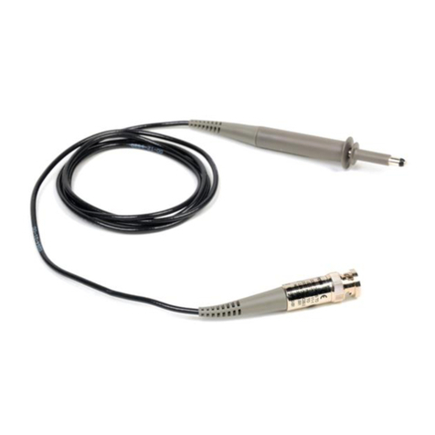
Tektronix
Tektronix P2100 User manual
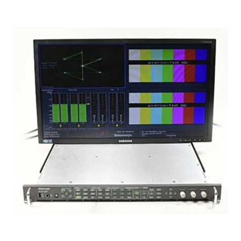
Tektronix
Tektronix WVR7200 User manual
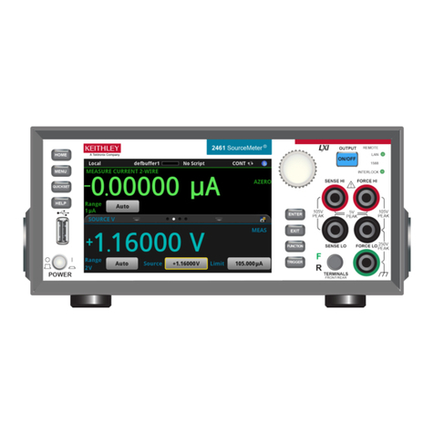
Tektronix
Tektronix Keithley SourceMeter 2461 User manual
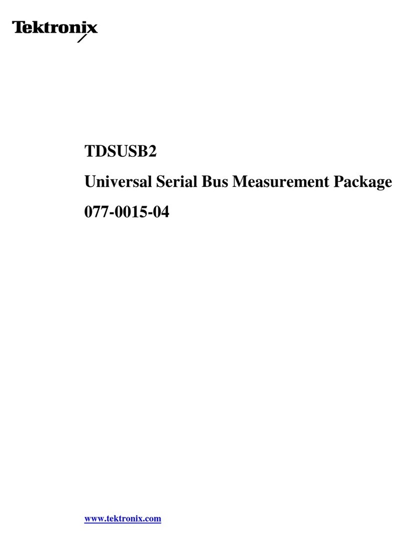
Tektronix
Tektronix TDS5032 User manual

Tektronix
Tektronix P7260 User manual
Tektronix
Tektronix RSA306B User manual
Tektronix
Tektronix Keithley 2182A User manual
Tektronix
Tektronix AA5001 User manual
Tektronix
Tektronix Keithley 4200A-SCS User manual
Tektronix
Tektronix TDP1000TDP1500 Manual
Popular Measuring Instrument manuals by other brands

Powerfix Profi
Powerfix Profi 278296 Operation and safety notes

Test Equipment Depot
Test Equipment Depot GVT-427B user manual

Fieldpiece
Fieldpiece ACH Operator's manual

FLYSURFER
FLYSURFER VIRON3 user manual

GMW
GMW TG uni 1 operating manual

Downeaster
Downeaster Wind & Weather Medallion Series instruction manual

Hanna Instruments
Hanna Instruments HI96725C instruction manual

Nokeval
Nokeval KMR260 quick guide

HOKUYO AUTOMATIC
HOKUYO AUTOMATIC UBG-05LN instruction manual

Fluke
Fluke 96000 Series Operator's manual

Test Products International
Test Products International SP565 user manual

General Sleep
General Sleep Zmachine Insight+ DT-200 Service manual
