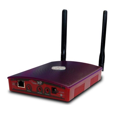
Teldat H2 RAIL Lite User manual

Teldat H2 RAIL Lite
Installation Manual
Copyright© Teldat-DM686-I Version 1.1 05/2016 Teldat S.A.
Teldat S.A. Manual
Teldat H2 RAIL Lite 1

Legal Notice
Warranty
This publication is subject to change.
Teldat S.A. offers no warranty whatsoever for information contained in this manual.
Teldat S.A. is not liable for any direct, indirect, collateral, consequential or any other damage connected to the deliv-
ery, supply or use of this manual.
Manual Teldat S.A.
2Teldat H2 RAIL Lite

Table of Contents
I ImportantInformation................................ 1
Chapter1 Description..................................... 2
1.1 Introduction...................................... 2
Chapter2 Installation...................................... 3
2.1 Connections...................................... 3
2.1.1 Connectingthepower.................................. 3
2.1.2 Dataconnection.................................... 4
2.1.3 Connecting to a WWAN antenna . . . . . . . . . . . . . . . . . . . . . . . . . . . . . 5
2.1.4 Connecting the WLAN antenna . . . . . . . . . . . . . . . . . . . . . . . . . . . . . . 7
2.1.5 Connecting the GPS antenna . . . . . . . . . . . . . . . . . . . . . . . . . . . . . . 7
2.1.6 Configurationconnection ................................ 7
2.2 InstallingtheSIMcard.................................. 9
2.2.1 IdentifyingtheSIMcards ................................ 9
2.2.2 InstallingtheSIM................................... 10
2.2.3 Closingthedevice.................................. 11
Chapter3 MeaningoftheLEDs............................... 12
Chapter4 Microswitches................................... 13
4.1 Procedure to ignore the configuration . . . . . . . . . . . . . . . . . . . . . . . . . . 13
Chapter5 Compliance.................................... 15
5.1 Manufacturerinformation ............................... 15
5.2 Safetywarnings ................................... 17
5.3 WEEEinformation.................................. 17
5.4 REACH....................................... 17
5.5 EC Declaration of Conformity. . . . . . . . . . . . . . . . . . . . . . . . . . . . . . 18
5.6 CEmarking..................................... 18
5.7 NationalRestrictions................................. 18
5.8 Operatingfrequency ................................. 19
Appendix A Technical Information. . . . . . . . . . . . . . . . . . . . . . . . . . . . . . . 20
A.1 Troubleshooting................................... 20
A.2 Maintenance..................................... 20
Teldat S.A. Table of Contents
Teldat H2 RAIL Lite i

A.2.1 Upgradingthesoftware................................ 20
A.3 Connectors ..................................... 20
A.3.1 POWERConnector.................................. 20
A.3.2 LANConnector.................................... 21
A.3.3 WWANConnectors.................................. 21
A.3.4 WLANConnectors.................................. 21
A.3.5 GPSConnector ................................... 22
A.3.6 ConfigurationConnector................................ 22
A.4 TechnicalSpecifications................................ 22
AppendixB RadioInformation................................. 25
B.1 RFLTEspecifications................................. 25
B.2 WIFISpecifications.................................. 26
Table of Contents Teldat S.A.
ii Teldat H2 RAIL Lite

I Important Information
Caution
The manufacturer reserves the right to make changes and improvements to the appropriate features in
both the software and hardware of this product, modifying the specifications of this manual without prior
notice.
The images presented on the front and back panels of the devices are provided as information
guideline only. Some small modifications may exist in the actual device.
Warning
The equipment is intended to be installed by Service Personnel and only handled by qualified person-
nel. If not, the device may be damaged and malfunction.
This device contains elements that are sensitive to electrostatic surges and shocks. Therefore, it is es-
sential when handling the equipment that an antistatic wriststrap is connected to the device chassis and
that this is placed on an antistatic mat. Furthermore, it is crucial to avoid any kind of contact between
the device components and necklaces, bracelets, rings, ties etc.
Note
Please note that when the device operates for prolonged periods of time under extreme conditions
(including high temperature and humidity) the service life of the device falls significantly.
Teldat S.A. Important Information
Teldat H2 RAIL Lite 1

Chapter 1 Description
1.1 Introduction
The Teldat H2 RAIL Lite router is an IP router conceived to work in hostile and extreme environments and designed
to be installed in rolling stock. Thanks to its ruggedized mechanics and special characteristics, which allow it to bear
extreme temperatures, this router is particularly suited for: rolling stock, automotive applications, industrial environ-
ments, industrial telecontrol, distribution installations for electricity, gas, water, etc.
Moreover, it enables the access to data networks through cellular or mobile telephony technologies. Thanks to its
modular design, the device can quickly adapt to the latest technologies.
The Teldat H2 RAIL Lite family is, therefore,compatible with GPRS, EDGE, UMTS, HSDPA, HSUPA, HSPA,
HSPA+, LTE, CDMA 2000 1xRTT, CDMA Ev-Do, etc.
The router can incorporate one or two cellular technology modules. This way, the device can be simultaneously con-
nected to different carrier networks in order to increase its capacity or to use them as backup when one of the net-
works is unavailable.
In addition, the latest technology in internal GPS (SiRF® Start IV) can be incorporated for positioning tasks in on-
board environments.
The Teldat H2 RAIL Lite family includes an integrated four-port Ethernet LAN Switch for local area networks.
Optionally, the Teldat H2 RAIL Lite may incorporate a Wireless LAN MINI-PCI module.
This manual will show you how to install and connect these devices.
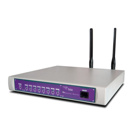
Fig. 1: Teldat H2 RAIL Lite: External aspect
Note
SIRF, SIRF Start and the SIRF logo are SIRF Technology, Inc. (a CSR plc company) trademarks.
Other products, services and names used in this document may have been registered by their respect-
ive proprietors.
1 Description Teldat S.A.
2Teldat H2 RAIL Lite

Chapter 2 Installation
2.1 Connections
Note
Before connecting the router, please read the following instructions carefully.
Workplace Conditions. Main Characteristics
This device is designed to be installed in a 19” Rack.
The electric current in power cables, telephone lines and communication cables is
dangerous. To prevent electric shocks, before installing, handling or opening the
equipment covers, connect and disconnect the cables as shown in the following
table:
To Connect To Disconnect
Make sure the power cable is not connected to the
device.
Disconnect the power supply from the power supply
cable.
Connect all data cables. Disconnect the power supply cable from the device.
Connect the power supply cable to the device. Disconnect the data cables.
Connect the power supply cable to the power supply.
2.1.1 Connecting the power
The Teldat H2 RAIL Lite router family is powered by an 110 V nominal DC power source. This device has no on/off
switch or fuse.
To comply with electrical safety regulations, this equipment must be connected to
the vehicle power network through a 1 amp approved thermo-magnetic circuit
breaker (ABB-S281-UC-K-1 or equivalent).
As an additional EMC measure, the H1 Rail device has two functional earth ter-
minals (on the front or back panel). One of the two must be grounded by means of
a cable with a section not less than 2 mm 2(AWG14).
The following image shows where the power connector is located. This is labeled as “ Power / 110 V DC” .
Fig. 2: Power supply connection
2.1.1.1 Power connector pins
The power connector installed on this device is an M12 4 pole code A male connector or equivalent.
PIN Signal M12 4P Code A male
Teldat S.A. 2 Installation
Teldat H2 RAIL Lite 3

1 110 V DC
2 110 V DC
3 0 V
4 0 V
Note
Connections 1-2 and 3-4 are redundant. However, for the device to remain available, we recommend
that you keep this redundancy.
2.1.1.2 Power cable
The power cable is not supplied with the device. Maximum estimated consumption for the device operating at 110 V
DC is approximately 150 mA. Therefore, any cable with a gauge greater than (or equal to) 0.2 mm 2(AWG24) is ac-
ceptable. The type of cable and its gauge will be determined by the characteristics of the female connector used.
E.g. for a female Phoenix Contact SACC-M12FS-4CON-PG7-M or equivalent, we would recommend a cable with an
outer diameter of 4-6 mm with 4 AWG24-AWG18 conductors.
The cable does not have to be shielded. If you use a shielded cable, we recommend that you connect the cable
shield to the ground at the other end of the device, in the power source or in both.
2.1.2 Data connection
The Teldat H2 RAIL Lite router has the following available data connectors:
2.1.2.1 LAN SWITCH
The Teldat H2 RAIL Lite router incorporates a 4 port Switch, 10/100BaseT with automatic MDI/MDIX to connect to a
local area network (LAN).
This device has a LINK LED that indicates the state of the connection.
Fig. 3: LAN Switch ports (4)
2.1.2.1.1 LAN connector pins
The LAN connector installed in the device is an M12 8P X-Code Female connector or equivalent.
PIN GE Signal -> Signal M12 8P X-Code Female connector
1 BI-DA+ ->Tx+ (1)
2 BI-DA- -> Tx- (2)
3 BI-DB+ -> Rx+ (3)
4 BI-DB--> Rx- (6)
2 Installation Teldat S.A.
4Teldat H2 RAIL Lite

5 BI-DD+ (4)
6 BI-DD- (5)
7 BI-DC-(7)
8 BI-DC+(8)
Note
Since the Switch integrated in the device has an automatic MDIX feature, you can use a PIN to PIN
cable in order to connect to another device without having to cross the Tx-Rx pairs.
2.1.2.2 AUX
The Teldat H2 RAIL Lite router family has a DB9 female connector on the front panel labeled AUX. This can be
used as a configuration port for the router or as a V.24 asynchronous serial port by means of a configuration com-
mand. The behavior or functionality of this interface must be previously configured. By default, this interface is con-
figured in the router’s configuration port mode. This section focuses on the connection necessary to operate in asyn-
chronous port mode.
This interface allows you to connect asynchronous serial devices that do not need hardware control signals. For in-
stance, it allows the connection of external modems or an asynchronous PPP WAN.
Another interesting feature of this port is the possibility of using it as a GPS data source in NMEA sentences
(GPS-DATA).
This interface only operates in compliance with the V24 norm. It does not have control signals, only data signals.
Therefore, this interface cannot control hardware flow. It does, however allow for software flow control (XON/XOFF).
You cannot configure parity in MARK and SPACE modes.
To do so, you need to connect the AUX port to an asynchronous terminal (or to a PC with terminal emulation).
For more information on how to use this as a configuration port for the router, please see section Configuration con-
nection on page 7.
Fig. 4: AUX Port
2.1.3 Connecting to a WWAN antenna
The Teldat H2 RAIL Lite router has up to 4 N connectors for WWAN antennas (3G).
Name 3G Module Antenna Function
MOD.1 ANT.1 MD1 Main
MOD.1 ANT.2 MD1 Aux. / diversity
MOD.2 ANT.1 MD2 Main
MOD.2 ANT.2 MD2 Aux. / diversity
Since the device does not have internal antennas, installing them is essential to improve the quality of the signal re-
ceived and transmitted by the Wireless WAN module (GPRS, UMTS, HSDPA, HSUPA, HSPA+, LTE, etc.).
Teldat S.A. 2 Installation
Teldat H2 RAIL Lite 5

The cable used to connect the antennas must be valid for RF signal communications of up to 2.6 GHz frequencies
and a 50 Ohm impedance. Please note that the quality and the length of the antenna cable (loss) may have an im-
pact on the quality of the RF signals transmitted and received and, consequently, on device coverage and the speed
at which the data is exchanged.
Note
For the Wireless WAN interface to be operative, the device must have the corresponding software li-
cense incorporated.
For each module, the device has two WWAN antenna connectors incorporated (ANT.1 and ANT.2).
Depending on the technology used for the connection, it will be necessary to use one (e.g. GPRS ) or two antennas
(e.g. LTE).
Installation of the antenna in the ANT.1 (Main) connector is mandatory. The antenna for the ANT.2 (Ext.Diversity)
connector may not be necessary.
In some models, if you are not going to install the ANT.2 Ext Diversity antenna you must configure the router accord-
ingly (disabling this antenna) to obtain optimum performance.
When you install both the ANT.1 Main and the ANT.2 Ext.Diversity antennas, the minimum distance between them
must be 7 cms and the maximum recommended distance is 25 cms.
In order to achieve optimum features, the installed radio frequency accessories (antennas and cables) should be
those recommended by Teldat.
The following image shows you where to find the antenna connectors for the WWAN modules.
Fig. 5: Antenna connectors for WWAN
2.1.3.1 Positioning the antenna
The antenna orientation and its location with respect to other wireless devices and radiation devices (such as com-
munication devices, personal computers, etc.) can have a significant impact on the device performance.
The antennas transmit and receive radio signals. Performance is also affected by environmental factors (such as the
distance between the device and the base station), physical obstacles and other interferences due to radio frequen-
cies (RF).
To achieve the best coverage, follow these steps:
• Whenever possible, place the antenna where there are no physical obstacles. Obstacles between the antenna and
the base station degrade the wireless signal. Place the antenna above ground level and steer it towards the
nearest base station.
• Density of materials also affects the antennas. Place them away from any type of wall, metal screens, mirrors, etc.
• Do not place the antenna near columns that can produce shadow areas and reduce the coverage zone.
• Keep the antenna away from metal pipes such as canals, air-conditioning, etc.
• Please bear in mind that other wireless devices such as telephones, microwaves, etc., can temporarily interfere
with the quality of the wireless signal.
• We do not recommend that you install the antennas near or between racks containing communication devices,
computers, etc. Use an extension cable and place the antenna outside.
The following recommendations are applicable to all wireless devices:
• Do not touch or move the antenna while the device is transmitting or receiving.
• When the antenna is transmitting, do not touch any equipment that contains devices that radiate very close to, or
2 Installation Teldat S.A.
6Teldat H2 RAIL Lite

touching, any exposed part of the body (particularly face and eyes).
• Do not install the device in areas where the atmosphere is potentially explosive.
• Wireless devices can cause interference in other devices. Do not use the device in areas where medical equip-
ment is installed.
2.1.4 Connecting the WLAN antenna
The Teldat H2 RAIL Lite has N connectors to connect up to 2 WLAN (Wi-Fi) antennas in the models that have this
interface.
Since the device does not have internal antennas, installing them is essential to improve the quality of the signal re-
ceived and transmitted by the Wireless LAN module.
The cable used to connect the antennas must be valid for RF signal communications of up to 2.4 GHz (5.7 GHz for
802.11a) frequencies and a 50 Ohm impedance. Please note that the quality and the length of the antenna cable
(loss) may have an impact on the quality of the RF signals transmitted and received and, consequently, on device
coverage and the speed at which the data is exchanged.
For the Wireless WAN interface to be operative, the device must have the corresponding software license incorpor-
ated.
The following image shows you where to find the antenna connectors for the WLAN modules.
Fig. 6: Antenna connectors for WLAN
2.1.5 Connecting the GPS antenna
The Teldat H2 RAIL Lite router has an FME connector to connect an active GPS antenna in the models equipped

with this interface.
Since the device does not have internal antennas, installing an active 3.3V external antenna in Teldat H2 RAIL Lite

routers is essential to improve the quality of the signal received by the GPS module.
The cable used to connect the antennas must be valid for RF signal communications of up to 1.5 GHz frequencies
and a 50 Ohm impedance. Please note that the quality and the length of the antenna cable (loss) may have an im-
pact on the quality of the RF signals received and, consequently, on the accuracy and speed at which the position is
obtained.
The following image shows you where to find the antenna connector for the GPS module.
Fig. 7: Antenna connector for GPS
2.1.6 Configuration connection
2.1.6.1 Configuring through the local console (AUX connector)
The Teldat H2 RAIL Lite router has a DB9 female connector on the front panel known as “AUX.”, which provides ac-
cess to the device’s local console or may operate as an asynchronous serial port. The behavior or functionality of this
interface must be previously configured. By default, this interface is configured in local console mode. This section
focuses on the connection for the local console mode.
To configure this, you must connect the “ AUX.” port to an asynchronous terminal (or to a PC with terminal emula-
Teldat S.A. 2 Installation
Teldat H2 RAIL Lite 7
tion).
Note
Configuration for the terminal must be as follows:
- Speed: 9600 bps.
- Eight data bits.
- One stop bit.
- No parity bit.
- No type of flow control.
Connection to the configuration port can be carried out via a DB9 Male and DB9 Female connector. If the terminal
has DB25 connectors, you will need to use an additional adapter.
Fig. 8: Connection for configuration
2.1.6.2 Configuring through the IP terminal (LAN1..4 connectors)
The Teldat H2 RAIL Lite router includes a default configuration that activates if the device has not been previously
configured.
The router’s default configuration sets the following IP access address and mask:
• IP Address: 192.168.1.1
• IP Mask: 255.255.255.0
Note
Some devices leave the factory with a customized configuration for a specific client. This personaliza-
tion can mean that the default configuration is different from the one shown above.
This initial configuration means you can access the device’s configuration console through the Telnet IP protocol. To
do this, carry out the following steps:
• Configure the Ethernet interface on the IP terminal (normally a PC) using the IP address from the following range
[192.168.1.2, 192.168.1.254] and mask 255.255.255.0. E.g. 192.168.1.2, 255.255.255.0.
• Connect the IP terminal’s Ethernet interface to any of the Ethernet Switch ports on the Teldat H2 RAIL Lite router
(the LAN1..4 connectors) through an appropriate Ethernet cable (M12 to RJ45).
• Start a Telnet session from the IP terminal to IP address 192.168.1.1 (the Teldat H2 RAIL Lite router default ad-
dress).
• The default configuration does not ask for login credentials (user/password) to access the console.
For further information on how to fully configure the device, please see the manuals provided by Teldat on the docu-
2 Installation Teldat S.A.
8Teldat H2 RAIL Lite

mentation CD or through the WEB page.
2.2 Installing the SIM card
The Teldat H2 RAIL Lite has one or two Wireless WAN interfaces. For them to operate, you may have to insert at

least one SIM card in the device.
There are certain services (CDMA) provided by several carriers in some countries that do not require SIM cards. In
installations where a SIM card is required, you must always insert at least one.
The Teldat H2 RAIL Lite has two SIM trays. Both are located inside the device.
In cases where it incorporates two modules, a SIM tray is automatically assigned to each module.
When only one SIM card is going to be used, it can be inserted into either of the two SIM trays. However, you must
remember to configure the router correctly so it selects the appropriate tray.
Having 2 SIM trays allows you to carry out some special configurations. One example is installing two SIMs and us-
ing one as a backup to the other. To carry out this type of configuration, you must set the tray that has to be associ-
ated to each SIM (since each SIM requires different configuration parameters).
Warning
This device is compatible with 1.8V and 3V SIMs. Do not install SIMs that do not support these
voltages.
Never install the SIM cards when the device is switched on.
Always disconnect the device from the main power supply before installing the SIM cards.
Always disconnect the device before removing the casing to access the trays.
When inserting the SIM cards, please protect yourself against electrostatic discharges (ESD).
Do not touch the SIM cards connectors.
To access the SIM trays you need to open the upper casing of the device. To do this, you need to undo the two
screws located on the upper part of the front panel, the two located on each of the side panels and the screw on the
upper part of the rear panel.
2.2.1 Identifying the SIM cards
The following figures show the location of the modules and the SIM trays:
Teldat S.A. 2 Installation
Teldat H2 RAIL Lite 9
Fig. 9: SIM tray #1 for MD1 Module
Fig. 10: SIM tray #2 for MD2 Module
When there are two modules, the SIM tray assignment is set and is as follows:
• Module MD1 for SIM #1
• Module MD2 for SIM #2
In devices where a single WWAN module is installed (MD1), if only one SIM card is going to be used, it can be inser-
ted in either SIM tray (#1 or #2). However, you must remember to configure the router correctly so it selects the ap-
propriate tray.
• Module MD1 # SIM #1 (default) or SIM #2
2.2.2 Installing the SIM
In order to insert a SIM card in the internal tray, locate the retaining flange (metal fastening with OPEN and LOCK on
it) so you can open the tray and place the SIM card on it. The steps are as follows:
(1) Push the fastening toward the OPEN arrow.
(2) Open the upper part of the tray.
(3) Insert the SIM card so it's flush with the edges of the tray.
(4) Return the tray to its original position.
2 Installation Teldat S.A.
10 Teldat H2 RAIL Lite
(5) While pressing on the tray, push the fastening toward the LOCK arrow so that the card is securely held.
Fig. 11: Instructions on how to insert the SIM in the internal tray
2.2.3 Closing the device
After installing the SIM card, you can then close the device. To do this, carry out the steps used to open the device in
reverse order paying special attention to communication modules’ Thermal Pad.
This element must be placed over the communication modules to expel the heat from the module outside (through
the device metal casing). The module should be in contact with the casing.
This pad quite often sticks to the casing when you open up the device. This is due to its rubbery consistency, as no
adhesive is used.
To assemble the device again, you need to carry out the following steps:
(1) Check that the Thermal Pad is located on top of the module. If it isn’t, check if it’s stuck to the casing. If it is, re-
move it from the casing and place it on top of the module.
(2) Refit the lid, first sliding it horizontally and then vertically so as not to ‘drag’ it over the pad.
(3) Replace the seven screws holding the cover.
Fig. 12: Example of a Thermal Pad assembled over the WWAN MD1. This must be assembled in both.
Teldat S.A. 2 Installation
Teldat H2 RAIL Lite 11
Chapter 3 Meaning of the LEDs
The following figure shows the positions of the LEDs on the front panel of the device:
Fig. 13: Teldat H2 RAIL Lite: Front panel
AWireless WAN interface channel 0 (cellular10/1).
OFF: Interface not available, not installed or not registered
ON: Registered, or registered and connected in the SIM operator Network.
- STEADY: Not transferring data.
- FLASHING: Transferring data.
BWireless WAN interface channel 1 (cellular11/1).
OFF: Interface not available, not installed or not registered
ON: Registered, or registered and connected in the SIM operator Network.
- STEADY: Not transferring data.
- FLASHING: Transferring data.
CThe device has a MINI-PCI slot where a Wireless LAN daughter card can be in-
stalled.
OFF: Interface not available, not installed or not registered
ON: Connecting, or connected and communication established.
-STEADY: Not transferring data.
- FLASHING: Transferring data.
LNK(4) Associated to each Ethernet switch connector (LAN1, LAN2, LAN3 and LAN4)
ON: Ethernet link established.
- STEADY: Not transferring data.
- FLASHING: Transferring data.
Note
During device initialization and boot, LEDs A, B, C and Link can turn on, turn off and flash. Once the
device has booted, the LEDs display functions described in the table above.
3 Meaning of the LEDs Teldat S.A.
12 Teldat H2 RAIL Lite
Chapter 4 Microswitches
The Teldat H2 RAIL Lite routers have a block of 8 available micro-switches used for maintenance and test tasks. In
this case, they are only used to load the default configuration.
This block of micro-switches can be found inside Teldat H2 RAIL Lite routers. You need to remove the top casing in
order to handle them, following the instructions set forth in section Installing the SIM on page 10.
These switches should not be handled by the user other than to establish the default configurations.
Note

For the device to operate correctly, all micro-switches must be in the OFF position.
4.1 Procedure to ignore the configuration
Follow the steps below if you have to discard the whole configuration of the device (for instance, if you cannot re-
member the password). When doing this, the device is generally connected to a terminal (PC) through the Console
port (AUX).
• Turn off the device.
• Using a screwdriver, move micro-switch ‘5’ to the ON position.
• Power up the device.
When the device is switched on, a message similar to the one shown below will appear on the configuration console
(AUX port):
**************************************************
**************************************************
**************************************************
BOOT CODE VERSION: 03.02 Apr 28 2009 11:25:37
gzip Apr 28 2009 11:19:34
P.C.B.: C8 MASK:0C10 Microcode:00E1
START FROM FLASH
BIOS CODE DUMP....................
BIOS DATA DUMP....
End of BIOS dump
BIOS CODE VERSION: 03.02
CLK=262144 KHz BUSCLK=65536 KHz PCICLK=32768 KHz L1
Date: 05/25/09, Monday Time: 13:37:06
SDRAM size: 64 Megabytes
BANK 0: 64 Megabytes (detected)
I_Cache: ON
D_Cache: ON Write-Back
FLASH: 16 Mb.
NVRAM: 128 Kb.
EEPROM: 2048 Bytes.
DPRAM: 8192 Bytes.
SWITCH 10/100
SECURITY ENGINE
PCI device: Host bridge
(Bus: 0, Device: 0, Function: 0)
(Vendor: 0x1057, Device: 0x18C1)
(Subs. Vendor: 0x0000, Subs. Device: 0x0000)
Slot 1 - PCI device: serial bus controller
(Bus: 0, Device: 10, Function: 0)
(Vendor: 0x1131, Device: 0x1561)
(Subs. Vendor: 0x5444, Subs. Device: 0x2800)
Teldat S.A. 4 Microswitches
Teldat H2 RAIL Lite 13

Slot 1 - PCI device: serial bus controller
(Bus: 0, Device: 10, Function: 2)
(Vendor: 0x1131, Device: 0x1562)
(Subs. Vendor: 0x5444, Subs. Device: 0x2800)
Slot 2 - PCI device: Ethernet controller
(Bus: 0, Device: 29, Function: 0)
(Vendor: 0x168C, Device: 0x0013)
(Subs. Vendor: 0x185F, Subs. Device: 0x1012)
Current production date: 09 21
Current software license: 20 12
S/N: 682/00100
BIOS MAC Add: 00-a0-26-c8-00-64
>>
........
TRYING APP CODE DUMP
(CONFIGURED) APPCODE1.BIN ver.: 0.10.7.32 0.0.0.0 ......
...........................................................
...........................................................
...................
APP DATA DUMP.......................................................
Running application
Default configuration used
Parsing text mode configuration ...
Configuration parsed
Initializing
Press any key to get started
On reaching this point, you can set micro-switch ‘5’ in the OFF position (you don’t have to power off the device). This
way, the saved configuration will run next time you restart the device. Also, bear in mind that the device configuration
is ignored on start up but it is not deleted.
4 Microswitches Teldat S.A.
14 Teldat H2 RAIL Lite

Chapter 5 Compliance
5.1 Manufacturer information
Brand Teldat
Manufacturer Teldat S.A.
Country Spain
Postal Address Isaac Newton 10, Parque Tecnologico de Madrid,28760 Tres Cantos, Madrid,
Spain
International Phone +34 91 807 65 65
Teldat S.A. 5 Compliance
Teldat H2 RAIL Lite 15

5.2 Safety warnings
Hazardous voltage. Danger to life! Do not open this equipment when it is switched
on.
Voltaje peligroso. ¡Peligro de muerte!
No abra este equipo cuando esté conectado a la corriente.
This equipment must be grounded. Never defeat the ground conductor or operate
the equipment in the absence of a suitably installed ground conductor. Contact the
appropriate electrical inspection authority or an electrician if you are uncertain
whether suitable grounding is available. When installing or replacing the unit, the
ground connection must always be made first and disconnected last.
Este equipo debe ser conectado a tierra. Nunca abandone la toma de tierra u
opere el equipo en ausencia de una toma de tierra adecuada. Contacte con la
autoridad eléctrica apropiada o con un electricista si tiene dudas sobre la situación
de su toma de tierra.Cuando instale o reemplace el equipo, se debe conectar la
conexión de tierra primero y desconectarla la última.
This equipment has been designed to work with an extended ambient temperature
range of up to 55 °C (131 °F) and under these conditions the metallic surface
could reach dangerous temperatures that may cause injuries.
Este equipo ha sido diseñado para funcionar con una temperatura ambiente de
rango extendido de hasta 55 ºC (131 ºF) y bajo estas condiciones la superficie
metálica puede alcanzar temperaturas que puden causar daños.
The equipment is intended to be installed by service personnel and only handled
by qualified personnel. If not, the device may be damaged and malfunction.
El equipo está diseñado para ser instalado por personal del servicio técnico y su
manejo debe realizarlo personal cualificado. De lo contrario, el equipo puede res-
ultar dañado y quedar inservible.
To comply with electrical safety regulations, this equipment must be connected to
the vehicle power network through a 1 amp approved thermo-magnetic circuit
breaker (ABB-S281-UC-K-1 or equivalent).
Para cumplir con la normativa de seguridad eléctrica, este equipo deberá ser con-
ectado a la red de alimentación del vehí-culo mediante un interruptor
magnetotérmico homologado de 1 amperio (ABB-S281-UC-K-1 o equivalente).
This device is compatible with 1.8 V and 3 V SIM cards. Do not install SIM cards
that do not support these voltages.
5 Compliance Teldat S.A.
16 Teldat H2 RAIL Lite
Table of contents
Other Teldat Network Router manuals

Teldat
Teldat K Seres User manual

Teldat
Teldat TLDPV00A1 User manual

Teldat
Teldat 5Ge-Rail User manual

Teldat
Teldat ATLAS 300 User manual

Teldat
Teldat RS1800 Series User manual

Teldat
Teldat ATLAS 60 NW User manual

Teldat
Teldat 4Ge User manual

Teldat
Teldat G1N User manual

Teldat
Teldat Regesta-PRO ER B User manual

Teldat
Teldat iM8-Cx User manual

Teldat
Teldat M2 User manual

Teldat
Teldat Connect 104KF TLDPM00A1 User manual

Teldat
Teldat 4Ge User manual

Teldat
Teldat RXL14000 User manual

Teldat
Teldat M2 User manual

Teldat
Teldat ATLAS 160 User manual

Teldat
Teldat Regesta PLC User manual

Teldat
Teldat T200 User manual

Teldat
Teldat IMBER SMART User manual

Teldat
Teldat RS300 Series User manual