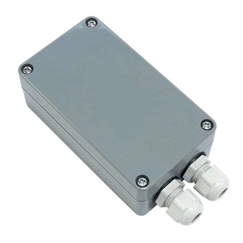
Teleco TVPLA868CC2EN User manual

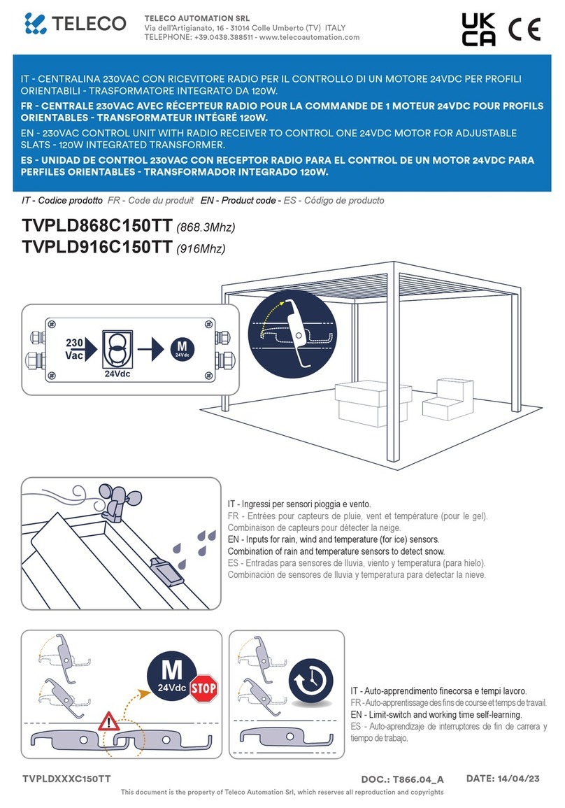
24VDC CONTROL UNIT WITH RADIO RECEIVER TO CONTROL ONE OR TWO 24VDC MOTORS WITH
ENCODER FOR ADJUSTABLE SLATS
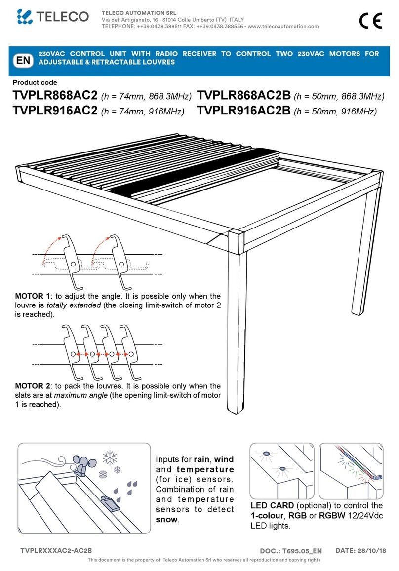
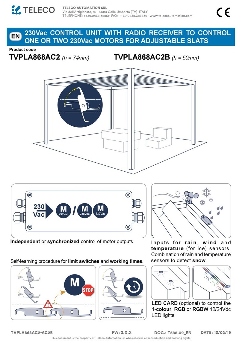
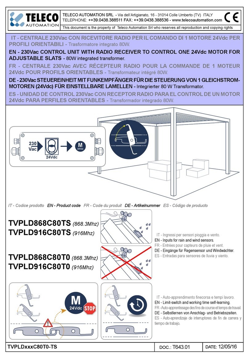
Inputs for rain, wind and
temperature (for ice) sensors.
Combination of rain and temperature
sensors to detect snow.
Self-learning procedure for limit switches and working times.
LED CARD (optional) to control the
1-colour, RGB or RGBW 24V
LED lights.
Independent or synchronized control of motor outputs.
Product code
EN
M
24Vdc /M
24Vdc M
24Vdc
M
24Vdc
M
24Vdc
24Vdc
M
230Vac
230
Vac M
230Vac M
230Vac M
230Vac
230
Vac
24Vdc
24Vdc
M
230Vac /
230
Vac M
230Vac M
230Vac
M
24Vdc
TVPLA868CC2EN (h = 74mm, 868.3MHz)
TVPLA868CC2ENB (h = 50mm, 868.3MHz)
TVPLA916CC2EN (h = 74mm, 916MHz)
TVPLA916CC2ENB (h = 50mm, 916MHz)
TELECO AUTOMATION SRL
Via dell’Artigianato, 16 - 31014 Colle Umberto (TV) ITALY
TELEPHONE: ++39.0438.388511 FAX: ++39.0438.388536 - www.telecoautomation.com
This document is the property of Teleco Automation Srl who reserves all reproduction and copying rights
DOC.: 697.03_EN
TVPLAXXXCC2EN-ENB DATE: 30/03/18

INDEX
1. Connections, adjustments and control unit warnings -------------------- page 3
2. MOTOR CONFIGURATION ----------------------------------------------------------- pages 4 - 7
2.1 Pergola with 1 motor
2.2 Pergola with 2 synchronized motors
2.3 Pergola with 2 independent motors
2.4 Setting of the current threshold during conguration
3. TRANSMITTERS --------------------------------------------------------------------- pages 8 - 10
3.1 Radio codes memorization
3.2 Radio codes deletion
3.3 Remote memorization of other radio codes
3.4 Remote deletion of a radio code
4. SENSORS ------------------------------------------------------------------------------- pages 11 - 13
4.1 WIND sensor
4.2 TEMPERATURE sensor
4.3 SNOW condition
4.4 RAIN sensor
4.5 Modication of the alarm automatic angles
5. CHANGE OF THE PRESET ANGLES ------------------------------------------------- page 14
6. FURTHER DETAILS ----------------------------------------------------------- page 15
5.1 Troubleshooting (what to do IF...)
5.2 Replacing the control unit
5.3 Quick learning of limit switches
7. Technical specications ----------------------------------------------------------- page 16 - 17
Accessories ------------------------------------------------------------------------------- page 18
WARNINGS
The product at issue must be installed, commissioned and maintained only by licensed and authorised people,
respecting the laws concerning the automatic covers. The system is powered by 24V . Before the connection to the
power supply make sure that the sensors and motors are correctly connected. A faulty connection of the motors (polarity
inversion) could damage them together with the connected mechanical elements. The power supply must supply the required
voltage and current according to the characteristics of the system. The power supply must be compliant with IEC60950-1
and must be protected against the short-circuit and over-voltage. Use a 2x1.5mm cable to connect the motors and the
control unit for length up to 6m, or 2x2.5mm cable for longer segments. PRODUCT DISPOSAL: at the end of this product’s
useful life, it must not be disposed of as domestic waste, but must be taken to a collection centre for waste electrical and
electronic equipment. To prevent inltration of water, wire the product as follows:
The manufacturer, Teleco Automation s.r.l, declares that the type of radio equipment is compliant with Directive 2014/53/
EU. The full text of the EU compliance declaration is available at the following Internet address: www.telecoautomation.
com/ce. In the view of a constant development of their products, the manufacturer reserves the right for changing technical
data and features without prior notice.

3
M1
M2
1+24V POWER SUPPLY
2 POWER SUPPLY GND
3 MOTOR 1 (OPEN)
4 MOTOR 1 (CLOSE)
5 MOTOR 2 (OPEN)
6 MOTOR 2 (CLOSE)
7 WIND SENSOR (BROWN)
8 WIND SENSOR (BLUE)
9RAIN SENSOR (WHITE, +12V )
10 RAIN SENSOR (BLUE, SIGNAL)
11 RAIN SENSOR (YELLOW, GND)
12 AERIAL RF
13 AERIAL GND
14 TEMPERATURE SENSOR (BLACK)
15 TEMPERATURE SENSOR (WHITE)
16 ENCODER M2 (VDD)
17 ENCODER M2 (Signal A)
18 ENCODER M2 (Signal B)
19 ENCODER M2 (GND)
20 ENCODER M1 (GND)
21 ENCODER M1 (Signal B)
22 ENCODER M1 (Signal A)
23 ENCODER M1 (VDD)
LED COLOUR STATUS MEANING
L1 RED ON until next manoeuvre MOTOR 1: Limit switch or alarm
Flashing during movement MOTOR 1 moving with encoder communication
L2 RED ON until next manoeuvre MOTOR 2: Limit switch or alarm
Flashing during movement MOTOR 2 moving with encoder communication
L3 BLUE ON Synchronized mode activated
One ash every second Synchronized mode activated (during conguration)
One ash every 2 s Independent mode activated (during conguration)
L4 RED One ash every 10 s Water draining alarm (par. 4.4, page 12)
Two quick ashes every 10 s Rain alarm (par. 4.4, page 12)
Three quick ashes every 10 s Ice / Snow alarm (par. 4.2 - 4.3, pages 11-12)
Four quick ashes every 10 s Wind alarm (par. 4.1, page 11)
Five quick ashes Unexpected absorption of one motor in synchronized mode
Six quick ashes Built-in motor limit switch activated
Seven quick ashes Motor stopped by current absorption over the threshold
Eight quick ashes Safety limit switch
Nine quick ashes Encoder signal error. The motor stops.
Ten quick ashes One motor is short-circuited
Twelve quick ashes Encoder signal disturbed. Abnormal motor operation.
One ash every 2 s Rain sensor is deactivated
One ash every 3 s Temperature sensor is deactivated
L5 RED ON Power ON
L3
Optional LED CARD
(only in TVPLAxxxCC2EN version)
Memory
10A Fuse
24V
Power supply
-
+
2
1
6
5
4
3
14
15
13
12
8
7
11
10
9
RAIN
sensor
WIND
sensor
Aerial
P1 P2
TEMP.
Sensor L2
L1
L5
DIP switch
ATTENTION! The electronic
board is protected by a 10A
fuse. The maximum allowed
power, including the plug-in
LED controller board, is 240W.
= Weather sensor alarms (from LOW to HIGH priority)
FIRST POWER ON: at rst power-on, the system is waiting
to be programmed with the memorization of at least one
transmitter (par. 3, page 8) and the conguration of the
motors and relative working time (see next pages).
1CONNECTIONS, ADJUSTMENTS AND CONTROL UNIT WARNINGS
= It takes effect DURING conguration
DIP MEANING
1 - 2 - 3 Setting of wind sensor threshold (see par. 4.1, page 11)
4 - 5 Motor control mode (see pages 4…7)
6Maximum motor current threshold set during conguration
(see par. 2.4, page 7)
not
used
L4
16 17 18 19
20 21 22 23
Encoder M1
Encoder M2
= MOTOR alarms

4
DIP4=OFF
DIP5=OFF
Pergola with 1 motor
1. MOTOR CONFIGURATION
2. SELF-LEARNING OF LIMIT SWITCHES (start from and intermediate point of the run)
ON
1 2 3 4 5 6
...
Continuous sound
L3 ashes
Press P1 and P2 simultaneously
and hold for 5 s
Press P1 and P2 simultaneously twice in quick succession and
hold them the second time for 5 s
...
P2
+
P1
( 5 s)
DO NOT change the DIP conguration. This change would be signalled by a new intermittent sound and the ashing of L3, and would require a new conguration procedure.
2.1
L1
L1
Closing
Opening
M
24Vdc Check that movement
stops when the limit switch
is reached (L1 ON)
If it doesn’t, change the
threshold as per PAR 2.4
(page 7) and repeat.
LIMIT SWITCHES
CLOSE OPEN
DIRECTION
P1 P2
If the direction is wrong, invert the motor wires.
= =
< 1 s
P2
+
P1
( 5 s)
P2
+
P1
complete
closing
complete
opening
complete
closing
complete
opening
... ... ... ...
MOTOR CONFIGURATION: Identify the correct product application from the 3 given below and follow the relative conguration procedure.
Attention: if the wrong application is selected, the conguration procedure must be repeated for the correct application.
LED L1 ashes during motor movements.

5
DIP4=OFF
DIP5=ON
Pergola with 2 synchronized motors
1. MOTOR CONFIGURATION
Together MOTOR 1 and MOTOR 2
2.2
...
Continuous sound
L3 ashes
Press P1 and P2 simultaneously
and hold for 5 s
...
P2
+
P1
( 5 s)
2. SELF-LEARNING OF LIMIT SWITCHES (start from and intermediate point of the run)
Press P1 and P2 simultaneously twice in quick succession and
hold them the second time for 5 s
L1+L2
L1+L2
Closing
Opening
M
24Vdc Check that movement
stops when the limit
switches are reached (L1
and L2 ON)
If it doesn’t, change the
threshold as per PAR 2.4
(page 7) and repeat.
LIMIT SWITCHES
CLOSE OPEN
DIRECTION
P1 P2
If the direction is wrong, invert the motor wires.
= =
< 1 s
P2
+
P1
( 5 s)
P2
+
P1 complete
closing
complete
opening
complete
closing
complete
opening
... ... ... ...
ON
1 2 3 4 5 6 DO NOT change the DIP conguration. This change would be signalled by a new intermittent sound and the ashing of L3, and would require a new conguration procedure.
LEDs L1 and L2 ash during motor movements.

6
DIP4=OFF
DIP5=OFF
Pergola with 2 independent motors
1. MOTOR 1 CONFIGURATION
DIP4=ON
DIP5=OFF
2. MOTOR 2 CONFIGURATION
2.3
...
Continuous sound
L3 ashes
Press P1 and P2 simultaneously
and hold for 5 s
...
P2
+
P1
( 5 s)
L1
L1
Closing
Opening
M
24Vdc Check that movement
stops when the limit switch
is reached (L1 ON)
If it doesn’t, change the
threshold as per PAR 2.4
(page 7) and repeat.
LIMIT SWITCHES
CLOSE OPEN
DIRECTION
P1 P2
If the direction is wrong, invert the motor wires.
= =
L2
L2
Closing
Opening
M
24Vdc Check that movement
stops when the limit switch
is reached (L2 ON)
If it doesn’t, change the
threshold as per PAR 2.4
(page 7) and repeat.
LIMIT SWITCHES
CLOSE OPEN
DIRECTION
P1 P2
If the direction is wrong, invert the motor wires.
= =

7
PRESSES Threshold (A)
1 0.5
2 1.0
3 1.5
4 2.0
5 2.5
6 3.0
7 3.5
8 4.0
9 4.5
The control unit uses a current threshold for motor stop. The thresholds may therefore be changed during conguration according to the selected mode (DIP4-5):
1. Turn the control unit OFF then ON again.
2. Within 10 seconds from power ON, set DIP6 to ON.
WITHIN 30 SECONDS:
3. Press P1 as many times as the desired level, from 1(minimum = 0.5 A) to 9(maximum = 4.5 A).
4. Set DIP6 to OFF to store the new value.
L4 will then ash as many times as the stored level. If P1 is not pressed within 30 seconds,the procedure is
automatically ended and the threshold remains unchanged.
ATTENTION: at the end of the procedure, DIP6 must be set to OFF and remain in that position during standard
operation of the control unit.
SETTING OF THE CURRENT THRESHOLD DURING CONFIGURATION
DIP6=ON
< 10 s < 30 s
P1 ...
/
DIP6=OFF
...
L4 ashes
2.4
3. SELF-LEARNING OF LIMIT SWITCHES (start from and intermediate point of the run)
MOTOR 1 rst, then MOTOR 2
Press P1 and P2 simultaneously twice in quick succession and
hold them the second time for 5 s
< 1 s
P2
+
P1
( 5 s)
P2
+
P1 complete
closing
complete
opening
complete
closing
complete
opening
... ... ... ...
= default value, unless otherwise indicated
on the technical label of the product.
ON
1 2 3 4 5 6 DO NOT change the DIP conguration. This change would be signalled by a new intermittent sound and the ashing of L3, and would require a new conguration procedure.
LEDs L1 and L2 ash during motor movements.

8
A
7/42 CHANNEL
TRANSMITTER
C
HOLD-TO-RUN COMMANDS
(2 or 3 BUTTONS)
3TRANSMITTERS
B
7/42 channel transmitter
CH1
CH2
CH3
CH4
CH5
CH6
CH7
Open (STOP)
Close (STOP)
Open (STOP)
Close (STOP)
Open
STOP
Close
AUTOMATIC COMMANDS
(2 or 3 BUTTONS)
CH5
CH6
CH7
Open
STOP
Close
CH5
CH6
CH7
Open
(hold-to-run)
Close
(hold-to-run)
STOP
CH1
CH2
CH3
CH4
CH5
CH6
CH7
Open (hold-to-run)
Close (hold-to-run)
Open (hold-to-run)
Close (hold-to-run)
Open (hold-to-run)
STOP
Close (hold-to-run)
Close (hold-to-run)
CH1
CH2
CH3
CH4
CH1
CH2
CH1
CH2
Open (hold-to-run)
Close (STOP)
CH1
CH2
CH3
CH4
CH1
CH2
CH1
CH2
Open (STOP)
3/18 channel transmitter
2 channel transmitter
E
CH1
CH2
CH3
CH4
CH5
CH6
CH7
33 %
50 %
70 %
100 % (Open)
Open (hold-to-run)
STOP
Close (hold-to-run,
minimum at 33%)
7/42 CHANNEL
TRANSMITTER (NO 0%)
1 - Light sensor
2 - OPEN button
3 - CLOSE button
4 - Light level memorization button
5 - Activation/deactivation light control
6 - Signal and programming LED
1
4
5
2
36
Transmitter with built-in light sensor
(see product instructions for details)
CH1
CH2
CH3
CH4
CH5
CH6
CH7
0 % (Closed)
33 %
66 %
100 % (Open)
Open (hold-to-run)
STOP
Close (hold-to-run)
D
GREEN MOUSE SCREEN

9
Radio codes memorization
1.1
3.1
P1 or P2
If the system is congured as pergola with 2 independent motors, it associates memorization procedure using P1 to motor 1 and memorization
procedure using P2 to motor 2. Note: the same radio code can in any case be associated with both motors.
In the other congurations memorization is possible using either P1 or P2.
* The buzzer will make a beep each time the button is pressed. ** According to the motor control mode
Press P1 or P2 (**) as many times as required by the type of desired memorization and hold the last time. The buzzer emits a continuous sound.
Press the button of the transmitter relative to the code to be memorized. Successful memorization is indicated by the intermittent sound of the buzzer
TYPE OF MEMORIZATION
(see description page 8)P1 or P2 **
A7/42 CHANNEL
TRANSMITTER
*
2x
Press any button
of the 7/42 channel
transmitter
BAUTOMATIC
COMMANDS
(2 or 3 BUTTONS)
*
3x
Press the button
of the transmitter
relative to the code
to be memorized.
CHOLD-TO-RUN
COMMANDS
(2 or 3 BUTTONS)
*
4x
Press the button
of the transmitter
relative to the code
to be memorized.
DGREEN MOUSE SCREEN *
11x
Press the button
2or 3of Green
Mouse Screen.
E7/42 CHANNEL
TRANSMITTER (NO 0%)
*
12x
Press any button
of the 7/42 channel
transmitter
continuous
sound
...
intermittent sound
HOLD

10
Radio code deletion
1.1
3.2
P1 or P2
If the system is congured as pergola with 2 independent motors, use P1 to delete associations with motor 1 and P2 for motor 2.
Carry out deletion with either P1 and P2 if the code is associated with both motors.
In the other congurations deletion is possible using either P1 or P2.
Press P1 or P2 (**) 5 times and hold. The buzzer emits an intermittent sound. Press the button of the transmitter relative to the code to be deleted within 10
seconds. Successful deletion is indicated by a continuous sound of the buzzer.
* The buzzer will make a beep each time the button is pressed. ** According to the motor control mode
ALL THE RADIO CODES *
6x (10 s)
continuous
sound
...
intermittent
sound
Press P1 or P2 6 times and the sixth time hold for 10 seconds. The buzzer emits a fast intermittent sound. Release when the sound becomes continuous.
x 3
Remote deletion of a radio code
Note: The button P3 is located inside the transmitter. The added radio code will have the same functions as the
code used for memorization. This procedure is compatible with any type of transmitter.
Press button P3 of the memorized transmitter and hold. The buzzer emits a
continuous sound. Press a button relative to an already memorized code. The
buzzer stops for 1 second and then starts the continuous sound again. Press the
button relative to the new code to be memorized. Successful memorization is
indicated by the intermittent sound of the buzzer.
...
P3
< 5 s
intermittent
sound
To be deleted
1 s
...
P3
New
< 5 s
continuous
sound
Memorized
< 5 s
continuous
sound
Memorized Memorized
Note: The button P3 is located inside the transmitter. If the radio code was
associated with both motors, carry out the deletion twice.
Press the button P3 of the memorized transmitter 3 times and hold. The buzzer
emits a slow intermittent sound. Press a button relative to the code to be deleted
within 5 seconds. Upon completion of deletion, the buzzer will stop.
1.1
3.3 3.4
Remote memorization of other radio codes
TYPE OF DELETION P1 or P2 **
SINGLE RADIO CODE *
5x
Press the button of the transmitter
relative to the code to be deleted.
HOLD
...
continuous
sound

11
WIND sensor
1.1
4.1 Factory setting
ACTIVATED
The anemometer (ANEM4) detects wind speed, which the control unit compares with the threshold set through DIPs 1-2-3 (see table).
The control unit is only compatible with anemometers generating 4 pulses per rev.
ALARM ACTIVATED when What happens with ALARM ACTIVATED ALARM NOT ACTIVE when
The detected speed is higher than
the set threshold (see table at side).
The control unit tilts the pergola slats at 33% of full
opening. The control unit executes no command.
The sensor has detected a lower speed
than the set threshold for 60 seconds.
L4
W
I
N
D
Alarm priority
HIGH
The temperature sensor (NTC 10K/3435K) activates whenever there is danger of ice forming.
TEMPERATURE sensor
1.1
4.2 Factory setting
DEACTIVATED
T
E
M
P
E
R
A
T
U
R
E
Alarm priority
MEDIUM
ALARM ACTIVATED when What happens with ALARM ACTIVATED ALARM NOT ACTIVE when
The measured temperature is below 2 °C. The control unit tilts the pergola slats to 66% of full opening. The
control unit only executes hold-to-run commands.
The measured temperature is above 3 °C.
t°
L4
Activation/deactivation of the TEMPERATURE sensor by means of the transmitter *
Deactivation
Press the “STOP” button of a memorized 7/42
or 3-channel transmitter 10 times and hold the
last time for 2 s. The buzzer emits 2 beeps.
L4 ashes once every 3 seconds.
Activation (only if the sensor is connected)
Press the “STOP” button of a memorized 7/42
or 3-channel transmitter 10 times and hold the
last time for 2 s. The buzzer emits a continuous
sound for 4 seconds.
STOP
L4 ashes
once every 3 s
(10x)
continuous
sound 4 s
STOP
(10x)
DIP1 DIP2 DIP3 Km/h
OFF OFF OFF 40
OFF OFF ON 45
OFF ON OFF 50
OFF ON ON 55
ON OFF OFF 60
ON OFF ON 65
ON ON OFF 70
ON ON ON 75
*** ***
* The motors must be stopped. ** The buzzer will make a beep each time the button is pressed. *** The motors make short movements
P1 ( 5 s)
continuous
sound
4 s
L4 ashes
once every 3 s
Activation/deactivation of the TEMPERATURE sensor by means of P1 *
ACTIVATION ***
(only if the sensor is connected)
DEACTIVATION ***
**
7x

12
To manage the alarm associated with snow, the temperature and the rain sensors must be combined.
SNOW condition
1.1
4.3 Factory setting
DEACTIVATED
S
N
O
W
Alarm priority
MEDIUM
ALARM ACTIVATED when What happens with ALARM ACTIVATED ALARM NOT ACTIVE when
The measured temperature is below 2 °C
and rain has been detected (see par. 4.4)
The control unit tilts the slats to 66% of full opening. The control
unit only executes hold-to-run commands.
The measured temperature is above 3 °C or
rain is no longer detected.
L4
P2
ACTIVATION
The motor must be
stopped.
*
x7
DEACTIVATION
The motor must be
stopped.
*
x7
HOLD
**
(5 s)
continuous
sound
**
Activation/Deactivation
of SNOW condition with P2.
* The buzzer will make a beep each time the button is pressed. ** The motors make short movements
ALARM ACTIVATED when What happens with ALARM ACTIVATED ALARM NOT ACTIVE when
The sensitive surface of the sensor detects
drops of water.
The control unit completely CLOSES the pergola slats. The
control unit executes no command.
The sensor doesn’t detect any drop.
System operation AFTER rain alarm (draining of water): once the rain alarm has ended, for the following 6 hours the control unit, upon receiving an
automatic movement command from the transmitter, will tilt the pergola slats to 33% to allow water to drain off. For 4 minutes the control unit can only execute
hold-to-run commands, thereby exiting from the alarm status.
RAIN sensor
1.1
4.4 Factory setting
ACTIVATED
Alarm priority
LOW
R
A
I
N
L4

13
Activation/deactivation of the RAIN sensor by means of the transmitter ***
Deactivation
Press the “STOP” button of a memorized
7/42 or 3-channel transmitter for 10 s. The
buzzer emits 2 beeps. L4 ashes once
every 2 seconds.
Activation
Press the “STOP” button of a memorized
7/42 or 3-channel transmitter for 10 s.
The buzzer emits a continuous sound
for 4 seconds.
STOP
L4 ashes
once every 2 s
(10 s) continuous
sound 4 s
STOP
(10 s)
**** ****
Change of the automatic alarm angles
1.1
4.5
Use the following procedures to change the default angles of the pergola slats associated with the wind alarm (33%) or the temperature/snow alarm (66%).
The system must have been congured and at least one transmitter memorized.
P1 o P2 **
Wind alarm
angle
*
x8
Temperature
or Snow
alarm angle
*
x9
Reset
default
angles
*
x10
HOLD
Put the slats to the
desidered angle,
then:
desidered
position
continuous
sound
(5 s)
1 s
2 s
3 s
continuous
sound
continuous
sound
Press P1 or P2 (**) as many times as required by the type of desired memorization and hold the last time.
The buzzer emits a continuous sound.
* The buzzer will make a beep each time the button is pressed. ** According to the motor control mode *** The motor must be stopped **** The motors make short movements
NOTE: after a new conguration procedure the automatic alarm angles are always reset to default values.

14
5Change of the preset angles (associated to the buttons CH1..CH4 of a 7/42 channel transmitter)
Note: The button P3 is located inside the transmitter.
Press the button P3 of the memorized
transmitter 6 times and hold for 5 sec.
The buzzer emits a slow intermittent
sound. Put the slat to the desired angle
then press the button P3 again to conrm.
Successful memorization is indicated by
the fast intermittent sound of the buzzer.
CH1
CH2
CH3
CH4
CH5
CH6
CH7
6x
...
P3
intermittent sound
Memorized
keep it pressed
( 5 s)
P3
Memorized
...
Press the button P3 of the memorized
transmitter 7 times and hold for 5 sec.
The buzzer emits a slow intermittent
sound. Put the slat to the desired angle
then press the button P3 again to conrm.
Successful memorization is indicated by
the fast intermittent sound of the buzzer.
CH1
CH2
CH3
CH4
CH5
CH6
CH7
7x
...
P3
intermittent sound
Memorized
keep it pressed
( 5 s)
P3
Memorized
...
Press the button P3 of the memorized
transmitter 8 times and hold for 5 sec.
The buzzer emits a slow intermittent
sound. Put the slat to the desired angle
then press the button P3 again to conrm.
Successful memorization is indicated by
the fast intermittent sound of the buzzer.
CH1
CH2
CH3
CH4
CH5
CH6
CH7
8x
...
P3
intermittent sound
Memorized
keep it pressed
( 5 s)
P3
Memorized
...
Press the button P3 of the memorized
transmitter 9 times and hold for 5 sec.
The buzzer emits a slow intermittent
sound. Put the slat to the desired angle
then press the button P3 again to conrm.
Successful memorization is indicated by
the fast intermittent sound of the buzzer.
CH1
CH2
CH3
CH4
CH5
CH6
CH7
9x
...
P3
intermittent sound
Memorized
keep it pressed
( 5 s)
P3
Memorized
...
Attention: use a transmitter associated only to the motor to be congured. After a new motor conguration procedure, the angles switch back to default values.

15
Problem Solution
At power-on, the control unit does not move the motors and emits no warning. The system needs to be programmed, see section 2.
L3 ashes and an intermittent sound starts after conguration. Repeat the procedure. At the end of it DO NOT change the DIP4-5 setting.
The conguration procedure does not start upon pressing P1 and P2 twice. P1 and P2 must be pressed simultaneously. There must be no more than 1 second
between pressing the rst and the second time.
During the manual movement test in the conguration procedure, the motors do
not stop automatically at the limit stop. Change the current threshold (section 2.4) before continuing with conguration.
There’s no continuous beep during transmitter memorization. There must be no more than 1 second between pressing the buttons.
It is impossible to memorize a transmitter. The radio code is already memorized or the memory is full.
After conguration, the engine stops and invert the direction. Remove any obstacles that block the movement.
The motor stops or there is abnormal functioning of the motor. Check the encoder signal wiring.
6.1 TROUBLESHOOTING (what to do IF…)
In the event of a defective control unit, if the provided memory (see below) is
still working and the revision of the board is > 9.x, it may be replaced without
losing the conguration parameters.
To do this, the control unit must not be powered:
• insert the memory card of the defective control unit into the new one;
• set the DIP switches of the new control unit as they were in the old one;
• switch the system on.
6.2 Replacing the control unit 6.3 Quick learning of limit switch
If the following have been already programmed
• motor control mode
• the correct motor direction
• at least one transmitter for each of the independent motor output
• current threshold to be applied
it is possible to carry out the SELF-LEARNING OF LIMIT SWITCHES without
accessing the control unit.
complete
closing
complete
opening
complete
closing
complete
opening
... ... ... ...
• Pergola with 2 synchronized motors: Together MOTOR 1 and MOTOR 2
• Pergola with 2 independent motors: MOTOR 1 rst, then MOTOR 2
Test the movement and the direction of the motors by
means of the memorized transmitter, after this keep the
button P3 of the transmitter pressed for 10 s.
Memorized
P3
( 10 s)
M1
M2
Memory

16
7TECHNICAL SPECIFICATIONS
56 mm
151 mm
Product
fastening holes
Power supply 24V
Max. power for each output 4,5A
Maximum power applicable to the board 240W
Fuse (blade) 10A
Operating temperature range -20° - +45°C
Reception frequency 868.3MHz / 916MHz
Radio memory capability (transmitters) 16
Rain sensor power supply 12V (max.100mA)
Anemometer 4 pulses/rotation (ANEM4)
Temperature probe NTC (R=10Kohm; B=3435K)
Protection rating IP54
Material of the box and its cover
(Not suitable for direct UV exposure) Thermoplastic ABS
185 mm
70 mm
56 mm
(TVPLAxxxCC2EN)
32 mm
(TVPLAxxxCC2ENB) 18 mm

17
TVPLAxxxCC2EN
TVPLAxxxCC2ENB
TVPLAxxxCC2EN
TVPLAxxxCC2ENB
Sensors Power supply
M1 + M2
(4 wires
cable)
Power supply M1
M2
LED lights
Wind
sensor
Rain
sensor
Temperature
sensor
Sensors
7TECHNICAL SPECIFICATIONS
M1
M2

18
Accessories
ANEM4
(WIND sensor)
TVSTRD00PSI24 - LED 1-colour
Independent or simultaneous control of 3 outputs.
24V power supply from the PLA control unit (60W per output).
TVRGB00PSI24 - LED RGB (red, green, blue)
24V power supply from the PLA control unit (60W per output).
TVRGBW00PSI24 - LED RGB+W (red, green, blue + white)
Independent control of RGB and WHITE outputs, by means of
separate memorization of transmitter channels.
24V power supply from the PLA control unit (60W per output).
LED CARD to control the 1-colour, RGB or RGBW 24V LED lights.
(optional only in TVPLAxxxCC2EN version)
RAIN102
(RAIN sensor)
TMP150
(TEMPERATURE sensor)
ATTENTION! Maximum power of the system (motors and lights) is 240W.

CENTRALE 24VDC CON RICEVITORE RADIO PER IL COMANDO DI 1 O 2 MOTORI 24VDC CON ENCODER
PER PROFILI ORIENTABILI
M
24Vdc
Ingressi per sensori pioggia, vento,
temperatura (per il ghiaccio).
Combinazione di sensori per rilevare
la neve.
Auto-apprendimento necorsa e tempi lavoro.
LED CARD (opzionale) per il controllo
di luci LED 24V 1-colore, RGB
o RGBW.
Comando indipendente o simultaneo delle uscite motore.
Codice prodotto
IT
M
24Vdc /M
24Vdc M
24Vdc
M
24Vdc
M
24Vdc
24Vdc
M
230Vac
230
Vac M
230Vac M
230Vac M
230Vac
230
Vac
24Vdc
24Vdc
M
230Vac /
230
Vac M
230Vac M
230Vac
TVPLA868CC2EN (h = 74mm, 868.3MHz)
TVPLA868CC2ENB (h = 50mm, 868.3MHz)
TVPLA916CC2EN (h = 74mm, 916MHz)
TVPLA916CC2ENB (h = 50mm, 916MHz)
TELECO AUTOMATION SRL
Via dell’Artigianato, 16 - 31014 Colle Umberto (TV) ITALY
TELEPHONE: ++39.0438.388511 FAX: ++39.0438.388536 - www.telecoautomation.com
This document is the property of Teleco Automation Srl who reserves all reproduction and copying rights
DOC.:697.03_IT
TVPLAXXXCC2EN-ENB DATE: 30/03/18

INDICE
1. Collegamenti, regolazioni e segnalazioni della centrale -------------------- pag. 3
2. CONFIGURAZIONE MOTORI ----------------------------------------------------------- pag. 4 - 7
2.1 Pergola a 1 motore
2.2 Pergola a 2 motori sincronizzati
2.3 Pergola a 2 motori indipendenti
2.4 Variazione della soglia di corrente in congurazione
3. TRASMETTITORI --------------------------------------------------------------------- pag. 8 - 10
3.1 Memorizzazione codici radio
3.2 Cancellazione codici radio
3.3 Memorizzazione remota di ulteriori codici radio
3.4 Cancellazione remota di un codice radio
4. SENSORI ------------------------------------------------------------------------------- pag. 11 - 13
4.1 Sensore VENTO
4.2 Sensore TEMPERATURA
4.3 Condizione NEVE
4.4 Sensore PIOGGIA
4.5 Modica delle angolazioni automatiche di allarme
5. MODIFICA DELLE ANGOLAZIONI PRESET ---------------------------------------- pag. 14
6. APPROFONDIMENTI ----------------------------------------------------------- pag. 15
6.1 RISOLUZIONE DEI PROBLEMI (cosa fare SE...)
6.2 Sostituzione della centrale
6.3 Apprendimento rapido dei limiti
7. Speciche tecniche --------------------------------------------------------------------- pag. 16 - 17
Accessori ------------------------------------------------------------------------------- page 18
AVVERTENZE
Il prodotto in oggetto deve essere installato, messo in servizio e controllato periodicamente solo da personale tecnico
qualicato nel rispetto delle normative vigenti riguardanti le coperture automatiche. Il sistema è alimentato a 24V .
Prima di collegare l’alimentazione assicurarsi che i sensori e i motori siano collegati correttamente. Un errato collegamento
(polarità discordi) potrebbe danneggiare i motori oltre che gli elementi meccanici ad essi collegati. L’alimentatore deve fornire
la tensione e la corrente richiesta dal dispositivo e dai motori collegati. L’alimentatore deve essere conforme alla norma
IEC60950-1 e protetto contro corto-circuiti e sovratensioni.Si consiglia l’uso di un cavo 2x1.5mm per collegare i motori al
dispositivo per una lunghezza no a 6m, mentre è opportuno un cavo 2x2.5mm per tratte superiori. SMALTIMENTO DEL
PRODOTTO: alla ne dalla vita utile, l’apparecchio non deve essere smaltito come riuto domestico, ma conferito in un
centro di raccolta riuti elettrici ed elettronici. Per evitare inltrazioni d’acqua si consiglia di cablare il prodotto come segue:
Il fabbricante, Teleco Automation s.r.l , dichiara che il tipo di Apparecchiatura radio è conforme alla direttiva 2014/53/UE. Il testo
completo della dichiarazione di conformità UE è disponibile al seguente indirizzo Internet: www.telecoautomation.com/ce La
dichiarazione di conformità può essere consultata sul sito: www.telecoautomation.com/ce. Nell’ottica di un continuo sviluppo
dei propri prodotti, il produttore si riserva il diritto di apportare modiche a dati tecnici e prestazioni senza preavviso.
This manual suits for next models
3
Table of contents
Languages:
Other Teleco Control Unit manuals

Teleco
Teleco TVPLA868CC2 User manual

Teleco
Teleco TVPLI868A01 User manual

Teleco
Teleco TVPLR868AC2 User manual

Teleco
Teleco TVPLD868C80TS User manual

Teleco
Teleco TVPLA868AC2 User manual

Teleco
Teleco TVPLS868TT3 User manual

Teleco
Teleco TVPLD868C150TT User manual

Teleco
Teleco TVPLA868AC2 User manual

Teleco
Teleco TVPLS868CS User manual
Popular Control Unit manuals by other brands

Kilowatt Labs
Kilowatt Labs SIRIUS 5000-384-A-1C-TM-SD-A-X-X-G user manual

LongSung Technology
LongSung Technology U6100 user manual

AtriCure
AtriCure ACM1 user manual

ProSoft Technology
ProSoft Technology PLX51-HART-4I quick start guide

Newland
Newland NLS-EM2096 Integration guide

Hirschmann
Hirschmann Dragon PTN-9-L3A-L user manual