Teleco TVPLS868TT3 User manual

EN - Product code
TVPLS868TT3 (868.3Mhz)
TVPLS916TT3 (916Mhz)
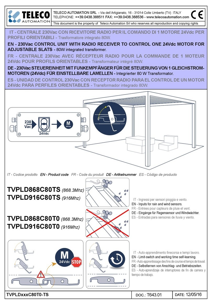
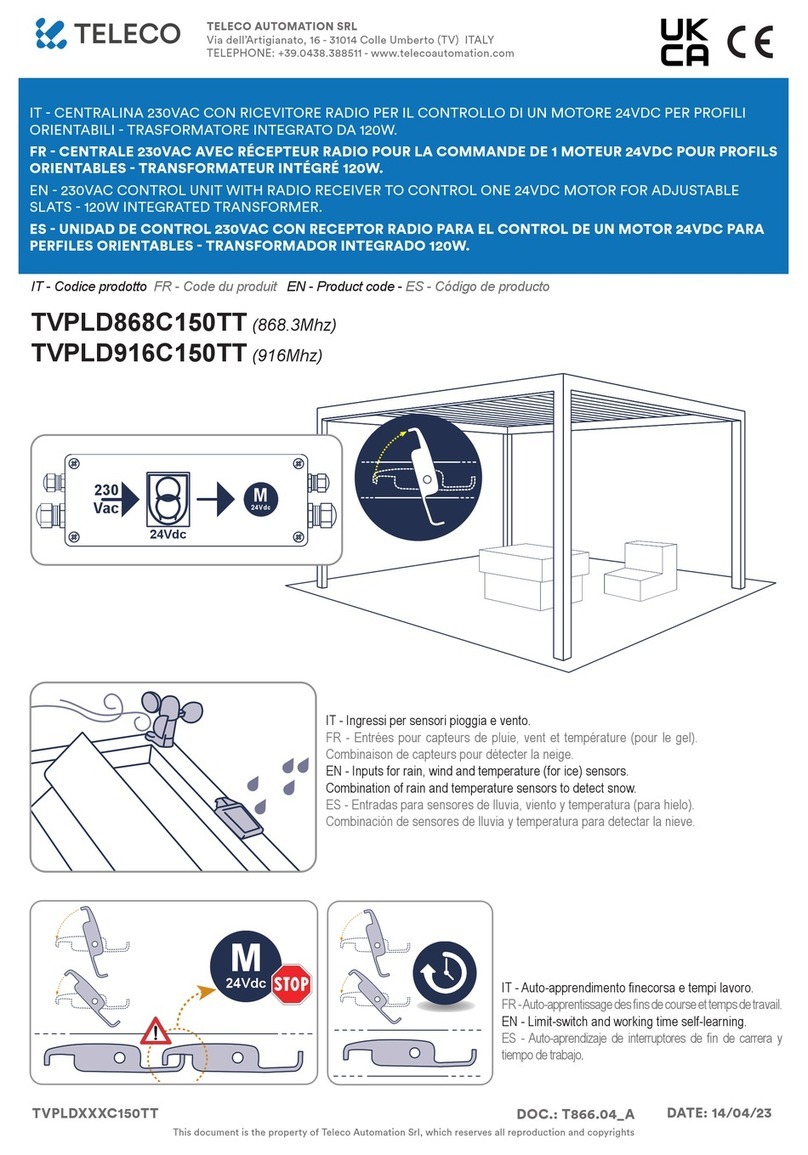
EN - 24VDC CONTROL UNIT WITH RADIO RECEIVER TO CONTROL ONE 24VDC MOTOR FOR ADJUSTABLE
SLATS.
M
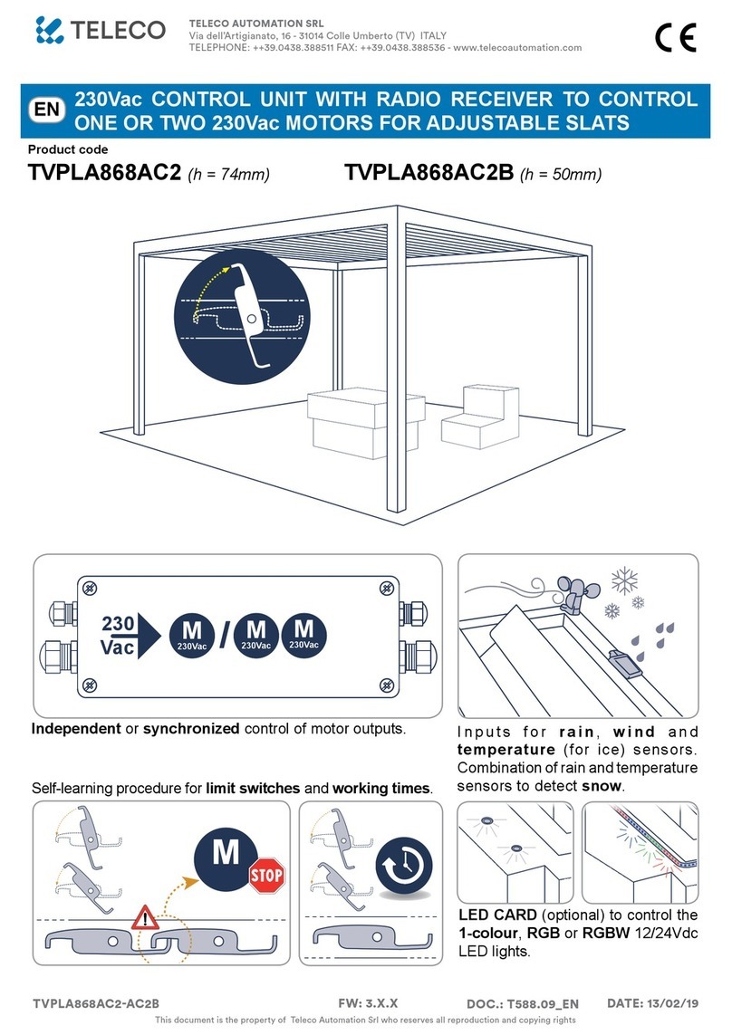
24Vdc Self-learning procedure for limit switches and working times.
Inputs for rain, wind and temperature (for ice) sensors. Combination of
rain and temperature sensors to detect snow.
M
24Vdc /M
24Vdc M
24Vdc
M
24Vdc
M
24Vdc
24Vdc
M
230Vac
230
Vac M
230Vac M
230Vac M
230Vac
230
Vac
24Vdc
24Vdc
M
230Vac /
230
Vac M
230Vac M
230Vac
TELECO AUTOMATION SRL
Via dell’Artigianato, 16 - 31014 Colle Umberto (TV) ITALY
TELEPHONE: ++39.0438.388511 FAX: ++39.0438.388536 - www.telecoautomation.com
DOC.: 774.01_EN
TVPLSXXXTT3 DATE: 30/03/18
This document is the property of Teleco Automation Srl who reserves all reproduction and copying rights

2
1. Connections and adjustments p. 6
2. TRANSMITTERS p. 3 - 5
2.1 Radio codes memorization
2.2 Working time conguration (necessary if 7/42 channel transmitters are used)
2.3 Radio codes deletion
2.4 Remote memorization of other radio codes
2.5 Remote deletion of a radio code
3. SENSORS p. 5 - 6
3.1 WIND sensor
3.2 RAIN sensor
3.3 SNOW condition
3.4 Activation/Deactivation rain sensor or rain sensor and temperature (Snow)
4. Technical specications p. 7
INDEX WARNINGS
The product at issue must be installed, commissioned and maintained only by licensed and
authorised people, respecting the laws concerning the automatic covers. The system is powered
by 24Vdc. Before the connection to the power supply make sure that the sensors and motors are
correctly connected. A faulty connection of the motors (polarity inversion) could damage them
together with the connected mechanical elements. The power supply must supply the required
voltage and current according to the characteristics of the system. The power supply must be
compliant with IEC60950-1 and must be protected against the short-circuit and over-voltage. Use
a 2x1.5mm cable to connect the motors and the control unit for length up to 6m, or 2x2.5mm cable
for longer segments. PRODUCT DISPOSAL: at the end of this product’s useful life, it must not be
disposed of as domestic waste, but must be taken to a collection centre for waste electrical and
electronic equipment. The manufacturer, Teleco Automation s.r.l, declares that the type of radio
equipment is compliant with Directive 2014/53 / EU. The full text of the EU compliance declaration
is available at the following Internet address: www.telecoautomation.com/ce
In the view of a constant development of their products, the manufacturer reserves the right for
changing technical data and features without prior notice.
1CONNECTIONS AND ADJUSTMENTS
M
AN
LED
-
+
14
13
LM
24Vdc IN
16
15
DIP SWITCH
P1
1
2
5
6
7
8
9
10
11
12
RN
LED
EN
DIP1 DIP2 (A)
OFF OFF 1
OFF ON 2
ON OFF 3
ON ON 4
Default
1AERIAL GND
2AERIAL RF
3TEMPERATURE SENSOR (BLACK)
4TEMPERATURE SENSOR (WHITE)
5INPUTS COMMON
6CLOSE/STOP INPUT (N.O.)
7OPEN/STOP INPUT (N.O.)
8RAIN SENSOR (YELLOW, GND)
9RAIN SENSOR (BLUE, SIGNAL)
10 RAIN SENSOR (WHITE,+12V)
11 WIND SENSOR (BLUE)
12 WIND SENSOR (BROWN)
13 MOTOR (CLOSE)
14 MOTOR (OPEN)
15 +24Vdc POWER SUPPLY
16 POWER SUPPLY GND
AN LED WIND SENSOR PULSES
RN LED RAIN SENSOR ACTIVE
L1 ON = RAIN ALARM
L2 FLASHING = WIND ALARM
LM LIMIT SWITCH LED
P1 PROGRAMMING BUTTON
3
4
L1 L2
M
MOTOR STOPS. The control unit stops the motors at the point of a mechanical
stop through current absorption. The threshold can be set with DIP1 and DIP2
(table). Attention! Check that the motor only stops at the mechanical stops
(LM = ON): increase the threshold if the motor stops during operation or
decrease if the motor continues to push against the mechanical stops.

3
BAUTOMATIC COMMANDS (2 or 3 BUTTONS)
7/42 channel transmitter
CH5
CH6
CH7
Open
STOP
Close
3/18 channel transmitter
Open
(STOP)
Close
(STOP)
2 channel transmitter
CH1
CH2
CH3
CH4
CH5
CH6
CH7
Open (STOP)
Close (STOP)
Open (STOP)
Close (STOP)
Open
STOP
Close
A1 BUTTON
CH1
CH2
CH3
CH4
CH5
CH6
CH7
0 % (CLOSED)
50 %
70 %
100 % (OPEN)
Open (hold-to-run)
STOP
Close (hold-to-run)
2TRANSMITTERS
CHx
Functions:
OPEN-STOP-CLOSE
or
CLOSE
7/42 channel transmitter
C7/42 CHANNEL TRANSMITTER
Press the button P1 as many times as requested by the type of memorization and keep it pressed. The buzzer emits a continuous sound.
Press the button of the transmitter relative to the code to memorize. The memorization is indicated by an intermittent sound of the buzzer.
TYPE OF MEMORIZATION P1
A1 BUTTON: *
1x
Press the button of the transmitter
relative to the code to memorize.
BAUTOMATIC COMMANDS
(2 or 3 BUTTONS)
*
2x
Press the button of the transmitter
relative to the code to memorize.
A1 BUTTON: *
3x
Press the button of the transmitter
relative to the code to memorize.
C7/42 CHANNEL TRANSMITTER *
4x
Press any button of the 7/42 channel
transmitter.
keep it
pressed
...
continuous
sound
OPEN STOP CLOSE
CLOSE
intermittent sound
2.1 RADIO CODES MEMORIZATION
P1
*The buzzer will make a beep each press.
EN

4
2.2 WORKING TIME CONFIGURATION (NECESSARY IF 7/42 CHANNEL TRANSMITTERS ARE USED)
Attention: the following procedure is necessary when using 7/42 channel transmitters (type C).
P1
*
10x
Command a
manoeuvre using
a memorized
transmitter or
by means of the
wired input.
Press P1 again or wait
25 seconds to quit
the procedure without
saving.
Note: this automatic cycle can be stopped with any
command. If working time is exceeded (90 s), the control
unit stops and emits an intermittent sound until any button
is pressed.
(>3 s)
...
intermittent sound
complete
closing
complete
opening
LM ashes
...
complete
opening
...
EN
P1
Press the button P1 10 times and keep it pressed for 3 seconds.
The buzzer emits an intermittent sound.
*The buzzer will make a beep each press.
2.3 RADIO CODES DELETION
TYPE OF DELETION P1
SINGLE RADIO CODE *
5x
Press the button of the transmitter
relative to the code to delete
Press 5 times the button P1 and keep it pressed. The buzzer emits an intermittent sound. Press the button of the transmitter relative to
the code to be deleted within 10 seconds. Successful deletion is indicated by a continuous sound of the buzzer.
ALL THE RADIO CODES *
6x
Press 6 times the button P1 and keep it pressed for 10 seconds. The buzzer emits a fast intermittent sound. Release when the sound
becomes continuous.
keep it pressed
...
(10 s)
continuous
sound
...
intermittent
sound
P1
continuous
sound

5
3x
REMOTE DELETION OF A RADIO CODE
Note: P3 button is located inside the transmitter. The added radio code will have the same functions of
the code used for the memorization. This procedure is compatible with any type of transmitter.
Press the button P3 of the memorized transmitter. The buzzer emits a
continuous sound. Press the button relative to a memorized code. The sound
stops for 1 second then it starts again. Press the button relative to the new
code. The memorization is indicated by an intermittent sound of the buzzer.
...
P3
< 5 s
intermittent
sound
To delete
1 s
...
P3
New
< 5 s
continuous
sound
Memorized
< 5 s
continuous
sound
Memorized Memorized
Note: P3 button is located inside the transmitter.
Press 3 times the button P3 of the memorized transmitter. The buzzer emits a
slow intermittent sound. Press the button relative to the code to delete within
5 seconds. The buzzer will stop sounding.
1.1
2.4 2.5
REMOTE MEMORIZATION OF FURTHER RADIO CODES
WIND SENSOR
1.1
3.1
The anemometer (ANEM4) detects wind speed, which the control unit compares with the threshold set through DIPs 3-4 (see table).
The control unit is only compatible with anemometers generating 4 pulses per rev.
ACTIVE ALARM when Once ACTIVE ALARM DEACTIVATED ALARM when
The measured speed is higher then
the set threshold (see the table).
The control unit moves the louvres to the 50% of complete
opening and it doesn’t execute any command. La ashes.
The sensor measures a speed lower than
the set threshold for at least 30 seconds.
DIP3 DIP4 Km/h
OFF OFF 40
OFF ON 50
ON OFF 60
ON ON 70
W
I
N
D
Alarm priority
HIGH LA ashes
EN
Factory setting
ACTIVATED

6
3.4 ACTIVATION/DEACTIVATION RAIN SENSOR OR RAIN + TEMPERATURE (SNOW)
ACTIVE ALARM when Once ACTIVE ALARM DEACTIVATED ALARM when
The sensitive surface of the sensor
detects any drops of water.
The control unit moves the louvres to the complete closing and
it doesn’t execute any command. Lr is ON.
The sensor doesn’t detect any drop.
RAIN SENSOR
1.1
3.2
R
A
I
N
LR ON Factory setting
ACTIVATED
STOP
(10 s)
continuous
sound
STOP
(10 s)
Sensor deactivation
Press the “STOP” button of a memorized 7/42
or 3-channel transmitter for 10 s.
The buzzer emits 2 beeps. The procedure
deactivates the sensor for 1 hour.
Sensor activation
Press the “STOP” button of a memorized 7/42
or 3-channel transmitter for 10 s. The buzzer
emits a continuous sound.
EN
To manage the alarm associated with snow, the temperature and the rain sensors must be both activated.
SNOW CONDITION
1.1
3.3 Factory setting
DEACTIVATED
S
N
O
W
ALARM ACTIVATED when What happens with ALARM ACTIVATED ALARM NOT ACTIVE when
The measured temperature is below 2 °C
and rain has been detected.
The control unit tilts the slats to 66% of full opening. The control
unit only executes hold-to-run commands.
The measured temperature is above 3 °C
or rain is no longer detected. If an automatic
opening command is trasmitted, the control
unit exits the alarm state.
LR ashing
The temperature sensor (NTC 10K/3435K) activates whenever there is danger of ice forming.
TEMPERATURE SENSOR
1.1
4.3
T
E
M
P
E
R
A
T
U
R
E
ALARM ACTIVATED when What happens with ALARM ACTIVATED ALARM NOT ACTIVE when
The measured temperature is below 2 °C
and the slats are closed.
The control unit tilts the pergola slats to 10% of full opening. The measured temperature is above 3 °C or
any command is received.
t°

EN - TECHNICAL SPECIFICATIONS
4
Power supply 24Vdc
Max. output power max. 4,5 A (24Vdc)
Rain sensor power supply 12Vdc (max.100mA)
Operating temperature ranget -20° ÷ +50°C
Working time 90 s
Protection rating IP54
Reception frequency 868.3 MHz
Radio memory capability (transmitters) 16
115 mm
65 mm
25 mm
15 mm
85 mm
53 mm
Not suitable for direct UV exposure
To prevent inltration of water, wire the product as follows:
Product fastening holes

TELECO AUTOMATION S.R.L.
ITALY
Tel. +39.0438.388511
info@telecoautomation.com
TELECO AUTOMATION FRANCE
FRANCE
Tel. +33.(0)472.145080
info@telecofrance.com
TELECO AUTOMATION GMBH
GERMANY
Tel. +49.(0)8122.9563024
info.de@telecoautomation.com
TELECO AUTOMATION OCEANIA PTY LTD
AUSTRALIA
Tel. +61.(07)5502.7801
info@telecoautomation.com.au
This document is the property of Teleco Automation Srl who reserves all reproduction and copying rights

FR - Code du produit
TVPLS868TT3 (868.3Mhz)
TVPLS916TT3 (916Mhz)
FR - CENTRALE 24VDC AVEC RÉCEPTEUR RADIO POUR LA COMMANDE DE 1 MOTEUR 24VDC POUR PROFILS
ORIENTABLES
M
24Vdc FR - Auto-apprentissage des ns de course et temps de travail.
FR - Entrées pour capteurs de pluie, vent et température (pour le gel).
Combinaison de capteurs pour détecter la neige.
M
24Vdc /M
24Vdc M
24Vdc
M
24Vdc
M
24Vdc
24Vdc
M
230Vac
230
Vac M
230Vac M
230Vac M
230Vac
230
Vac
24Vdc
24Vdc
M
230Vac /
230
Vac M
230Vac M
230Vac
TELECO AUTOMATION SRL
Via dell’Artigianato, 16 - 31014 Colle Umberto (TV) ITALY
TELEPHONE: ++39.0438.388511 FAX: ++39.0438.388536 - www.telecoautomation.com
DOC.: 774.01_FR
TVPLSXXXTT3 DATE: 30/03/18
This document is the property of Teleco Automation Srl who reserves all reproduction and copying rights

2
INDEX
1. Branchements et réglages p. 2
2. ÉMETTEURS p. 3 - 5
2.1 Mémorisation des codes radio
2.2 Conguration du temps de travail (nécessaire en cas d’utilisation d’émetteurs 7/42 canaux)
2.3 Suppression des codes radio
2.4 Mémorisation à distance d’autres codes radio
2.5 Suppression à distance d’un code radio
3. CAPTEURS p. 5 - 6
3.1 Capteur de VENT
3.2 Capteur de PLUIE
3.3 Sécurité NEIGE
3.4 Activation/désactivation du capteur de PLUIE ou de PLUIE+TEMPERATURE (NEIGE)
4. Spécications techniques p. 7
AVERTISSEMENTS
Le produit en objet doit être installé, mis en service et vérifié périodiquement seulement
par des techniciens qualiés, conformément aux normes en vigueur pour les appareillages
électriques. Le système est alimenté en 24V . Avant la mise sous tension, s’assurer
que les capteurs ainsi que le(s) moteur(s) sont raccordés de manière correcte. Un mauvais
branchement du ou des moteurs peut entrainer leur endommagement ainsi que celui de la
structure. L’alimentation doit pouvoir fournir la puissance nécessaire à l’ensemble des éléments.
En outre, elle doit être conforme à la norme IEC60950-1 ainsi qu’être protégée contre les court-
circuits et les surtensions. Pour le raccordement du ou des moteurs à la centrale, utiliser un câble de
2x1,5mm² jusqu’à 6m, au delà, utiliser un câble 2x2,5mm². ÉLIMINATION DU PRODUIT: à la n de
la durée de vie utile de ce produit, il ne doit pas être éliminé comme tout autre déchet domestique.
Le fabricant, Teleco Automation s.r.l, déclare que le type d’équipement radio est conforme avec
la directive 2014/53/EU. Le texte intégral de la déclaration de conformité EU est disponible à
l’adresse internet suivante: www.telecoautomation.com/ce Dans l’optique d’un développement
constant de ses produits, le fabricant se réserve le droit de modier les données techniques ou les
fonctionnalités sans préavis.
1BRANCHEMENTS ET RÉGLAGES
M
AN
LED
-
+
14
13
LM 24Vdc IN
16
15
DIP SWITCH
P1
1
2
5
6
7
8
9
10
11
12
RN
LED
FR
DIP1 DIP2 (A)
OFF OFF 1
OFF ON 2
ON OFF 3
ON ON 4
Default
FIN DE COURSE. La centrale est en mesure d’arrêter les moteurs à la
butée de n de course au travers de l’absorption de courant. Le seuil est
réglable au moyen des DIP1 et DIP2 (tableau). Attention! Contrôler que le
moteur s’arrête bien aux ns de course (LM = ON): augmenter le seuil si
le moteur s’arrête pendant la manœuvre ou s’il continue à forcer contre les
butées mécaniques.
1MASSE ANTENNE
2ANTENNE RF
3CAPTEUR DE TEMPÉRATURE (NOIR)
4CAPTEUR DE TEMPÉRATURE (BLANC)
5COMMUN ENTRÉES
6ENTRÉE FERMETURE/STOP (N.O)
7ENTRÉE OUVERTURE/STOP (N.O)
8CAPTEUR DE PLUIE (JAUNE, MASSE)
9CAPTEUR DE PLUIE (BLEU, SIGNAL)
10 CAPTEUR DE PLUIE (BLANC,+12V)
11 ANÉMOMÈTRE (BLEU)
12 ANÉMOMÈTRE (MARRON)
13 MOTEUR (FERMETURE)
14 MOTEUR (OUVERTURE)
15 ALIMENTATION (+24Vdc)
16 MASSE ALIMENTATION
AN LED IMPULSIONS ANÉMOMÈTRE
RN LED CAPTEUR DE PLUIE DÉCLENCHÉ
L1 ALLUMÉ = ALARME PLUIE
L2 FEU CLIGNOTANT = ALARME VENT
LM LED FIN DE COURSE
P1 BOUTON DE PROGRAMMATION
3
4
L1 L2
M

3
BCOMMANDES AUTOMATIQUES (2 ou 3 BOUTONS)
Émetteur 7/42 canaux
CH5
CH6
CH7
Ouverture
STOP
Fermeture
Émetteur 3/18 canaux
Ouverture
(STOP)
Fermeture
(STOP)
Émetteur 2 canaux
CH1
CH2
CH3
CH4
CH5
CH6
CH7
Ouverture (STOP)
Fermeture (STOP)
Ouverture (STOP)
Fermeture (STOP)
Ouverture
STOP
Fermeture
A1 BOUTON
CH1
CH2
CH3
CH4
CH5
CH6
CH7
0 % (FERMETURE)
50 %
70 %
100 % (OUVERTURE)
Ouverture (maintenue)
STOP
Fermeture (maintenue)
2ÉMETTEURS
CHx
Fonctions:
Ouverture-STOP-Fermeture
ou
Fermeture
Émetteur 7/42 canaux
CÉMETTEUR 7/42 CANAUX
Appuyer sur le bouton P1 le nombre de fois requis par le type de mémorisation et le maintenir appuyé. L’avertisseur sonore émet un son continu.
Appuyer sur le bouton de l’émetteur concernant le code à mémoriser. La mémorisation est conrmée par des bips rapides.
TYPE DE MÉMORISATION P1
A1 BOUTON: *
1x
Appuyer sur le bouton de l’émetteur
concernant le code à mémoriser.
BCOMMANDES AUTOMATIQUES
(2 ou 3 BOUTONS)
*
2x
Appuyer sur le bouton de l’émetteur
concernant le code à mémoriser.
A1 BOUTON: *
3x
Appuyer sur le bouton de l’émetteur
concernant le code à mémoriser.
CÉMETTEUR 7/42 CANAUX *
4x
Appuyer sur un quelconque bouton
de l’émetteur 7/42 canaux.
maintenue
...
Son
continu
son intermittent
2.1 MÉMORISATION DES CODES RADIO
P1
*L’avertisseur sonore émet un bip à chaque pression.
FR
OUVRE STOP FERME
FERME

4
2.2 CONFIGURATION DU TEMPS DE TRAVAIL (NÉCESSAIRE EN CAS D’UTILISATION D’ÉMETTEURS 7/42 CANAUX)
Attention : il est indispensable d’effectuer la procédure suivante pour pouvoir utiliser les émetteurs à 7/42 canaux (type C).
P1
*
10x
Lancer une
manœuvre au
moyen d’un
émetteur
mémorisé ou
d’une commande
laire.
Réappuyer sur P1 ou
attendre 25 secondes
pour quitter la procédure
sans sauvegarde.
Note: il est possible d’interrompre ce cycle automatique avec n’importe
quelle commande. Si le temps de travail maximal (90 s) est dépassé, la
centrale s’arrête en déclenchant un son intermittent qui dure jusqu’au
moment où l’on appuie sur un bouton quelconque.
(>3 s)
...
son intermittent
Fermeture
complète
Ouverture
complète
LM clignote
...
Ouverture
complète
...
FR
P1
Appuyer 10 fois de suite sur le bouton P1 et le maintenir appuyé
pendant 3 s. L’avertisseur sonore émet un son intermittent.
2.3 SUPPRESSION DES CODES RADIO
TYPE DE
SUPPRESSION P1
UN SEUL CODE RADIO *
5x
Appuyer sur un bouton de l’émetteur
concernant le code à supprimer.
Appuyer 5 fois de suite sur le bouton P1 et le maintenir appuyé. L’avertisseur sonore émet un son intermittent. Dans les 10 secondes
qui suivent, appuyer sur un bouton de l’émetteur concernant le code à supprimer. La suppression est conrmée par un son continu.
TOUS LES CODES RADIO *
6x
Appuyer 6 fois de suite sur le bouton P1 et le maintenir appuyé pendant 10 secondes. L’avertisseur sonore émet des bips rapides.
Lorsque l’avertisseur sonore émet un son continu, relâcher le bouton.
...
(10 s)
Son continu
...
son intermittent
P1
maintenue
*L’avertisseur sonore émet un bip à chaque pression.
Son continu

5
SUPPRESSION À DISTANCE D’UN CODE
RADIO
1.1
2.4 2.5
MÉMORISATION À DISTANCE D’AUTRES CODES RADIO
CAPTEUR DE VENT
1.1
3.1
L’anémomètre (ANEM4) détecte la vitesse du vent et la centrale la compare au seuil réglé au moyen des DIPS 3-4 (voir tableau).
La centrale est compatible seulement avec les anémomètres à 4 impulsions/tour.
L’ALARME SE DÉCLENCHE quand Que fait-il quand l’ALARME SE DÉCLENCHE L’ALARME NE SE DÉCLENCHE PAS quand
La vitesse détectée est supérieure
au seuil réglé (voir ci-contre).
La centrale intervient en faisant pivoter les lames de la
pergola à 50% de l’ouverture complète. LA clignote. La
centrale n’accepte aucune commande.
Le capteur détecte pendant 30 secondes
une vitesse inférieure au seuil réglé.
DIP3 DIP4 Km/h
OFF OFF 40
OFF ON 50
ON OFF 60
ON ON 70
V
E
N
T
Priorité alarme
HAUTE LA clignote
3x
Note : Le bouton P3 se trouve à l’intérieur de l’émetteur. Le code radio ajouté aura les mêmes fonctions que le
code utilisé pour la mémorisation. La procédure est compatible avec n’importe quel type d’émetteur.
Appuyer sur le bouton P3 de l’émetteur déjà mémorisé et le maintenir appuyé.
L’avertisseur sonore émet un son continu. Appuyer sur un bouton concernant un
code déjà mémorisé. L’avertisseur s’arrête un instant avant d’émettre de nouveau
un son continu. Appuyer sur le bouton concernant le code à mémoriser du nouvel
émetteur. La mémorisation est conrmée par des bips rapides.
...
P3
< 5 s
son intermittent
à supprimer
1 s
...
P3
Nouveau
< 5 s
Son
continu
Mémorisé
< 5 s
Son
continu
Mémorisé Mémorisé
Note : Le bouton P3 se trouve à l’intérieur de l’émetteur.
Appuyer trois fois de suite sur le bouton P3 de l’émetteur déjà mémorisé et le
maintenir appuyé. L’avertisseur émet des bips lents. Appuyer dans l’espace de 5
secondes sur le bouton concernant le code à supprimer. Dès que la suppression
a été effectuée, l’avertisseur sonore s’arrête de sonner.
Réglage d’usine
ACTIVÉ
FR

6
An de gérer efcacement la détection de neige, il est nécessaire de combiner les capteurs de température (NTC 10K/3435K) et de pluie.
SÉCURITÉ NEIGE
1.1
3.3
N
E
I
G
E
L’ALARME SE DÉCLENCHE quand Que fait-il quand l’ALARME SE DÉCLENCHE L’ALARME NE SE DÉCLENCHE PAS quand
La température relevée est sous 2°C et de
la pluie a été détectée.
La centrale intervient en faisant pivoter les lames de
la pergola à 66% de l’ouverture complète. La centrale
n’accepte aucune commande.
La température relevée est supérieure à 3°C ou il n’y a pas de détection
de pluie. Si l’on délivre une commande d’ouverture automatique au
moyen de l’émetteur la centrale sort de l’état d’alarme.
Réglage d’usine
DÉSACTIVÉ
Attention: si le contact de la sonde (13-14) devait rester ouvert (non connecté) et l’alarme se déclenche, la centrale pivote les lames de la pergola à 66% de
l’ouverture complète avec des mouvements intermittents.
LR clignote
Désactivation:
Appuyer pendant 10 s sur le bouton «STOP»
d’un émetteur mémorisé (7/42 ou 3 canaux).
L’avertisseur émet 2 bips. La procédure désactive
le capteur pendant 1 heure.
Activation:
Appuyer pendant 10 s sur le bouton «STOP»
d’un émetteur mémorisé (7/42 ou 3 canaux).
L’avertisseur sonore émet un son continu.
STOP
(10 s)
STOP
(10 s) Son continu
3.4 ACTIVATION/DÉSACTIVATION DU CAPTEUR DE PLUIE OU DE PLUIE + TEMPERATURE (NEIGE)
Le capteur de température (NTC 10K/3435K) intervient en cas de risque de formation de glace. S’il n’est pas utilisé il faut connecter la borne 13
à la borne 14.
CAPTEUR DE TEMPÉRATURE
3.5
T
E
M
P
É
R
A
T
U
R
E
L’ALARME SE DÉCLENCHE quand Que fait-il quand l’ALARME SE DÉCLENCHE L’ALARME NE SE DÉCLENCHE PAS quand
La température relevée est sous 2°C . La centrale intervient en faisant pivoter les lames de la pergola à
10% de l’ouverture complète.
La température relevée est supérieure à 3°C
ou une nouvelle commande vient reçue.
t°
FR
L’ALARME SE DÉCLENCHE quand Que fait-il quand l’ALARME SE DÉCLENCHE L’ALARME NE SE DÉCLENCHE PAS quand
La surface sensible du capteur détecte
des gouttes d’eau.
La centrale intervient en faisant pivoter les lames de la pergola
jusqu’à la FERMETURE complète. LR allumé.
La centrale n’accepte aucune commande.
Le capteur ne détecte pas de pluie.
CAPTEUR DE PLUIE
1.1
3.2
P
L
U
I
E
LR allumé Réglage d’usine
ACTIVÉ

FR - SPÉCIFICATIONS TECHNIQUES
4
Alimentation 24Vdc
Puissance maximale de sortie max. 4,5 A (24Vdc)
Alimentation du capteur de pluie 12Vdc (max.100mA)
Température de fonctionnement -20° - +50°C
Temps de travail 90 s
Degré de protection IP54
Fréquence de réception 868.3 MHz
Capacité mémoire radio (émetteurs) 16
115 mm
65 mm
25 mm
15 mm
85 mm
53 mm
Pas d’exposition directe aux UV
Trous de xation du produit
Pour éviter les inltrations d’eau, il est conseillé de câbler le produit comme indiqué ci-dessous:

TELECO AUTOMATION S.R.L.
ITALY
Tel. +39.0438.388511
info@telecoautomation.com
TELECO AUTOMATION FRANCE
FRANCE
Tel. +33.(0)472.145080
info@telecofrance.com
TELECO AUTOMATION GMBH
GERMANY
Tel. +49.(0)8122.9563024
info.de@telecoautomation.com
TELECO AUTOMATION OCEANIA PTY LTD
AUSTRALIA
Tel. +61.(07)5502.7801
info@telecoautomation.com.au
This document is the property of Teleco Automation Srl who reserves all reproduction and copying rights
This manual suits for next models
1
Table of contents
Languages:
Other Teleco Control Unit manuals

Teleco
Teleco TVPLA868AC2 User manual

Teleco
Teleco TVPLD868C150TT User manual

Teleco
Teleco TVPLA868AC2 User manual

Teleco
Teleco TVPLS868CS User manual

Teleco
Teleco TVPLI868A01 User manual

Teleco
Teleco TVPLA868CC2 User manual

Teleco
Teleco TVPLA868CC2EN User manual

Teleco
Teleco TVPLD868C80TS User manual

Teleco
Teleco TVPLR868AC2 User manual
Popular Control Unit manuals by other brands

Outform
Outform OF2021 Wi-fi connection guide

National Instruments
National Instruments SCXI-1160 user manual

Rockwell Automation
Rockwell Automation Trusted TMR manual

Speco
Speco IMP100DL quick start guide

Pure Aqua
Pure Aqua WS1TC Installation and programming manual

Emakefun
Emakefun RF-NANO operating instructions