2
INDICE
1. Connessioni e regolazioni p. 2
2. Trasmettitori p. 3 - 5
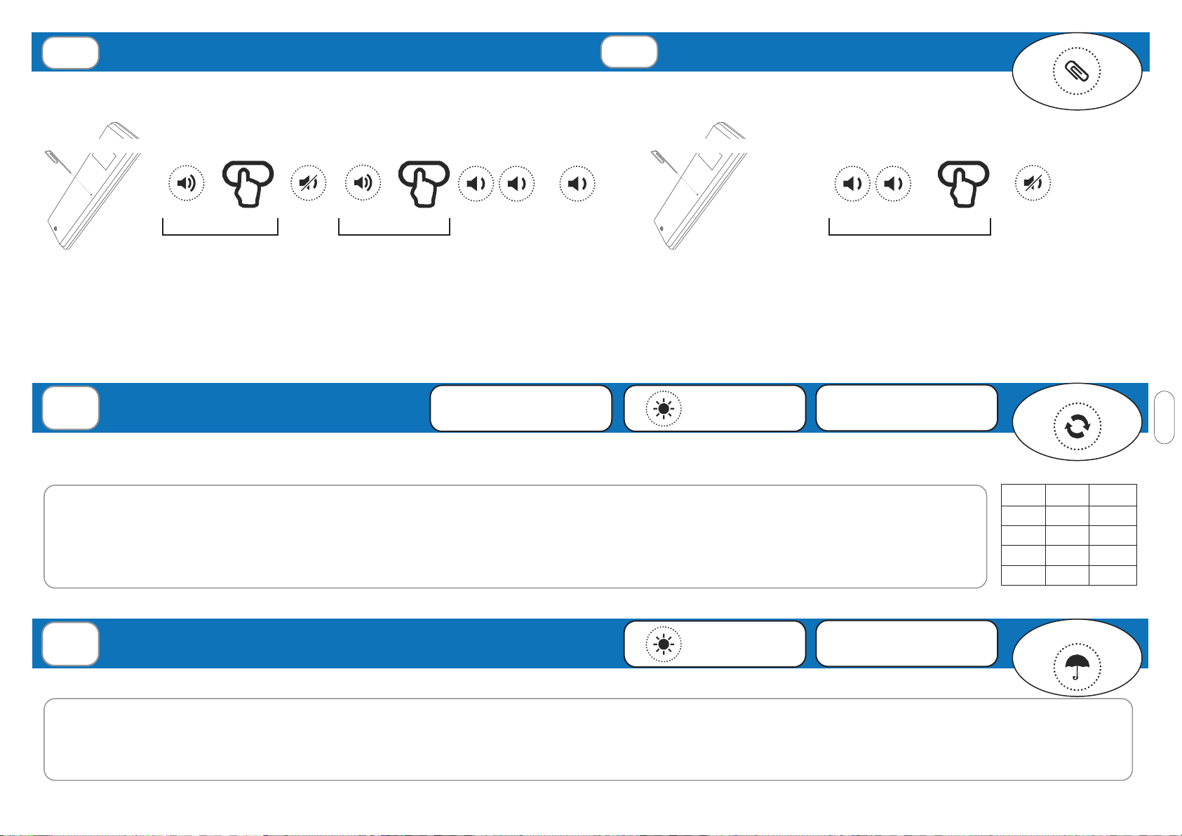
2.1 Memorizzazione codici radio
2.2 Congurazione tempo lavoro (necessaria se si usano trasmettitori 7/42)
2.3 Cancellazione codici radio
2.4 Memorizzazione remota di ulteriori codici radio
2.5 Cancellazione remota di un codice radio
3. Sensori p. 5 - 6
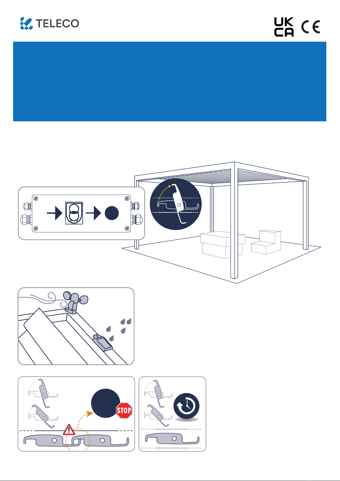
3.1 Sensore vento
3.2 Sensore pioggia
3.3 Condizione neve
3.4 Attivazione/disattivazione sensore pioggia o condizione neve (pioggia+temp.)
4. Apprendimento automatico dei limiti da remoto p. 6
5. Speciche tecniche p. 22
AVVERTENZE
Il prodotto in oggetto deve essere installato, messo in servizio e controllato periodicamente solo da
personale tecnico qualicato nel rispetto delle normative vigenti riguardanti le coperture automatiche.
Tutti i collegamenti devono essere previsti per un’alimentazione generale monofase 230Vac. Per la
disconnessione dalla rete utilizzare un interruttore onnipolare con un’apertura dei contatti di almeno 3,5
mm. Predisporre tutti i dispositivi di sicurezza necessari ed utilizzare materiali di collegamento idonei
secondo le attuali normative sulla sicurezza elettrica. I cavi di collegamento devono avere una sezione
adeguata al carico applicato. Prima di collegare l’alimentazione assicurarsi che i sensori e i motori siano
collegati correttamente. Un errato collegamento (polarità discordi) potrebbe danneggiare i motori oltre
che gli elementi meccanici ad essi collegati. Si consiglia l’uso di un cavo 2x1.5mm per collegare il motore
al dispositivo per una lunghezza no a 6m, mentre è opportuno un cavo 2x2.5mm per tratte superiori.
SMALTIMENTO DEL PRODOTTO: alla ne della vita utile, l’apparecchio non deve essere smaltito come riuto
domestico, ma conferito in un centro di raccolta riuti elettrici ed elettronici. Con la presente Teleco Automation
s.r.l. dichiara che il prodotto è conforme ai requisiti essenziali, ed alle altre disposizioni pertinenti, stabilite dalla
direttiva 1999/5/CE. La dichiarazione di conformità può essere consultata sul sito: www.telecoautomation.com/
ce. Nell’ottica di un continuo sviluppo dei propri prodotti, il produttore si riserva il diritto di apportare modiche
a dati tecnici e prestazioni senza preavviso.
IT
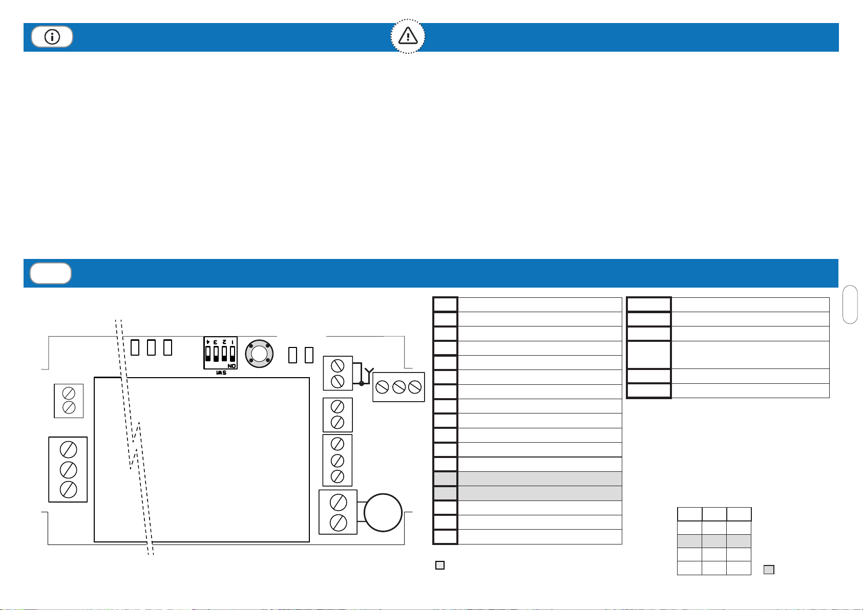
1CONNESSIONI E REGOLAZIONI
DIP1 DIP2 (A)
OFF OFF 1
OFF ON 2
ON OFF 3
ON ON 4Default
FINECORSA. La centrale è in grado di
arrestare i motori in corrispondenza di un
fermo meccanico, per assorbimento di
corrente. La soglia può essere impostata
con DIP1 e DIP2 (tabella). Attenzione!
Controllare che il motore si fermi solo in
corrispondenza dei necorsa (LM = ON):
aumentare la soglia se il motore si ferma
durante la manovra o diminuire se il motore
continua a spingere sui fermi meccanici.
AN LED IMPULSI SENSORE VENTO
RN LED SENSORE PIOGGIA ATTIVO
LA LAMPEGGIANTE = ALLARME VENTO
LR ACCESO = ALLARME PIOGGIA
LM LED FINE CORSA
P1 TASTO DI PROGRAMMAZIONE
M
RN
LED
LR LA LM
8 9 10
DIP SWITCH P1
2
1
5
4
3
15
16
17
7
6
12
11
AN
LED
13
14
Se non usati, chiudere i terminali 13-
14 con un ponte
1MOTORE (CHIUDE)
2MOTORE (APRE)
3SENSORE PIOGGIA (YELLOW, GND)
4SENSORE PIOGGIA (BLUE, SIGNAL)
5SENSORE PIOGGIA (WHITE,+12V)
6SENSORE VENTO (BLUE)
7SENSORE VENTO (BROWN)
8COMUNE INGRESSI
9INGRESSO CHIUDE/STOP (N.O.)
10 INGRESSO APRE/STOP (N.O.)
11 ANTENNA RF
12 ANTENNA GND
13 SENSORE TEMPERATURA
14 SENSORE TEMPERATURA
15 ALIMENTAZIONE 230Vac (FASE)
16 ALIMENTAZIONE 230Vac (NEUTRO)
17 TERRA