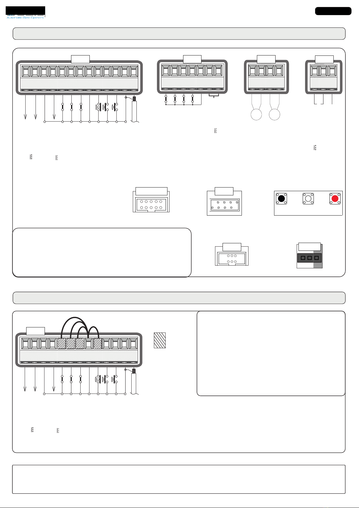
4.1 SAR N..
n clamps 2 and
The automation can be opened or closed through an
impulse transmitted to this input (via e button,
eboard, etc.). To connect other Start devices (for ex. the
magnetic loop) refer to the respective instructions
Note 1: In DEAD MAN logic it is necessar to hold the
Start button pressed to open the automation
Note 2: In 2 BUTTONS logic the connected Start device
onl performs the opening
4. S N.. n clamps and
If this button is pressed the engine stops immediatel in whatever condition or position it is. A new Start
command will be required to restore the movement.
ote After the Stop command, the engine will always re-start in closing
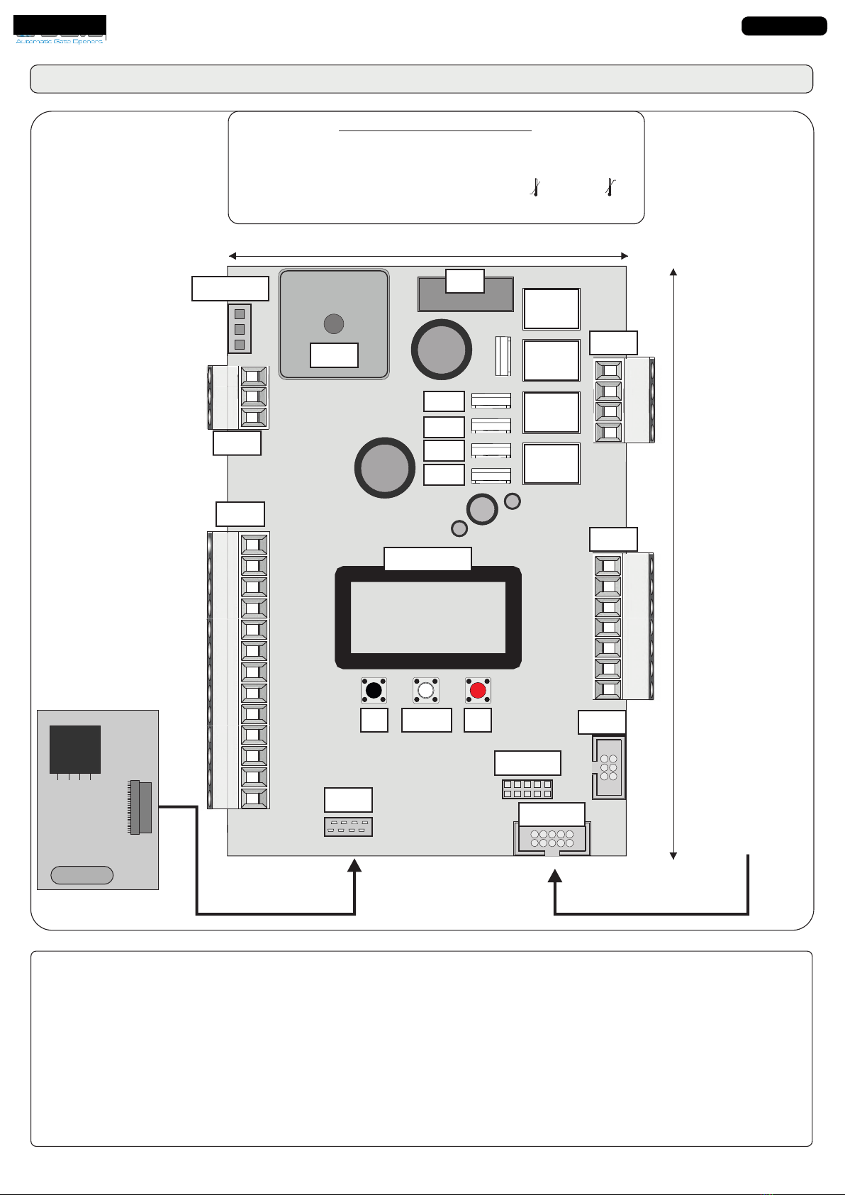
4 - CONNECTIONS ON CN1
RX1
N1
4 21
RX2
TX1
TX2
Start
Stop
Common
Antenna
Common
Photocell 1
Common
24VL 600 mA max
(Accessories-Lamp)
Photocell 2
Partial Opening START
N1
1 12 11 1 4.2 ARIAL ENING SAR N..
n clamps 2 and 4
The input allows to obtain the partial opening. It is possible
to manage the opening space through the men or
through the OLLY 3. It is also possible to manage the
partial opening pause time through the men 1
Note 1: In 2 BUTTONS logic, the connected Partial
Opening Start device onl performs the closing
Note 2: In DEAD MAN logic, it is necessar to hold the
Partial Opening Start button pressed to close the gate
Note : If this contact is engaged during the pause (eg.
Timer), the gate will not close until releasing
4.4 ELL 1 AND ELL 2
ma m clamp CM clamp CM clamp
otocell clamp otocell clamp
Note 1: To perform the self-test, connect the T positive to the clamp 10 (AU) and activate the Phototest
function on men4 From the ES menu it is possible to activate the self-test also on a
single photocell, choosing from the menu options.
Note 2: The default settings are: ELL 1 closing ELL 2 opening
for further functions and management, see menu-9 and menu-98
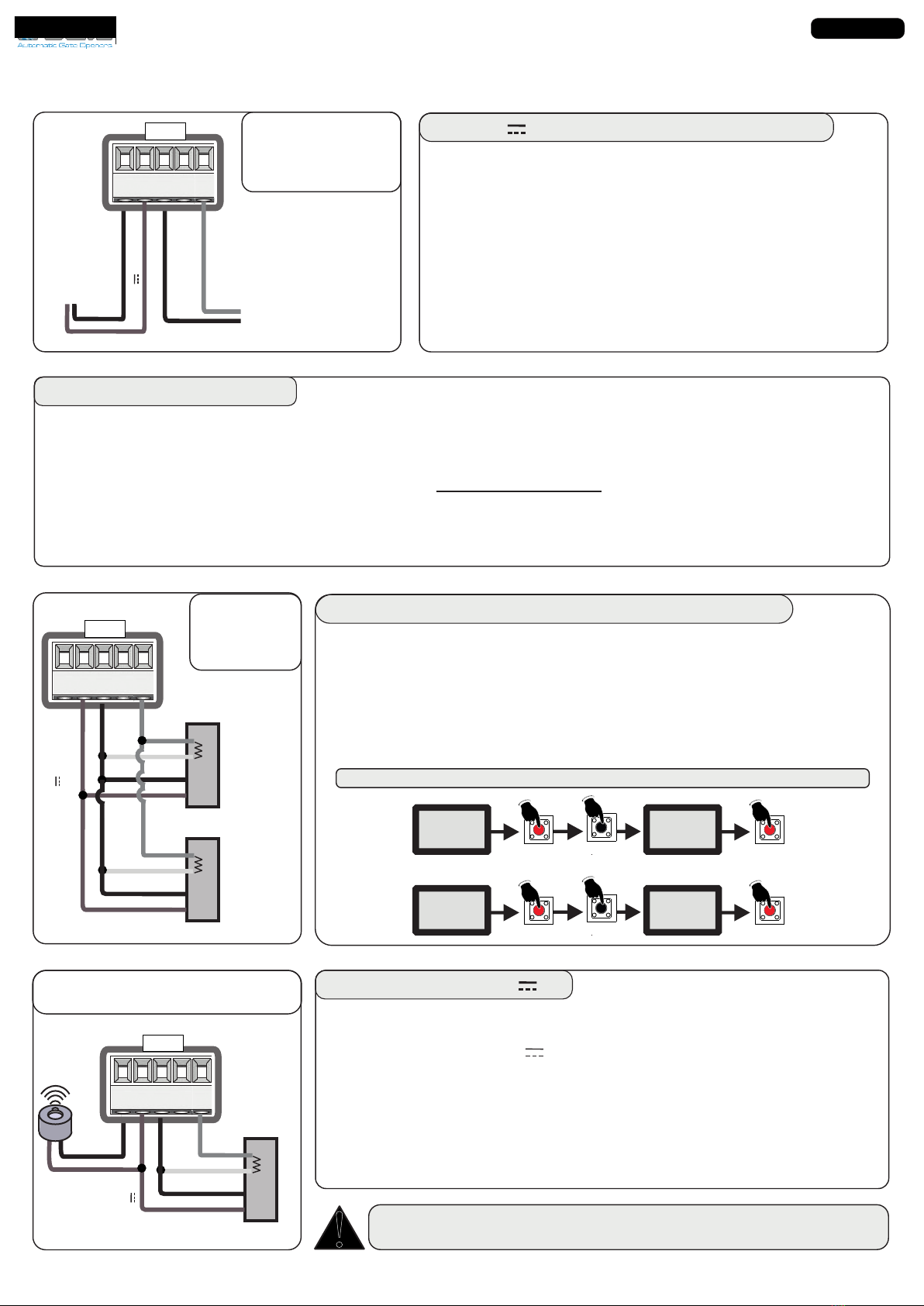
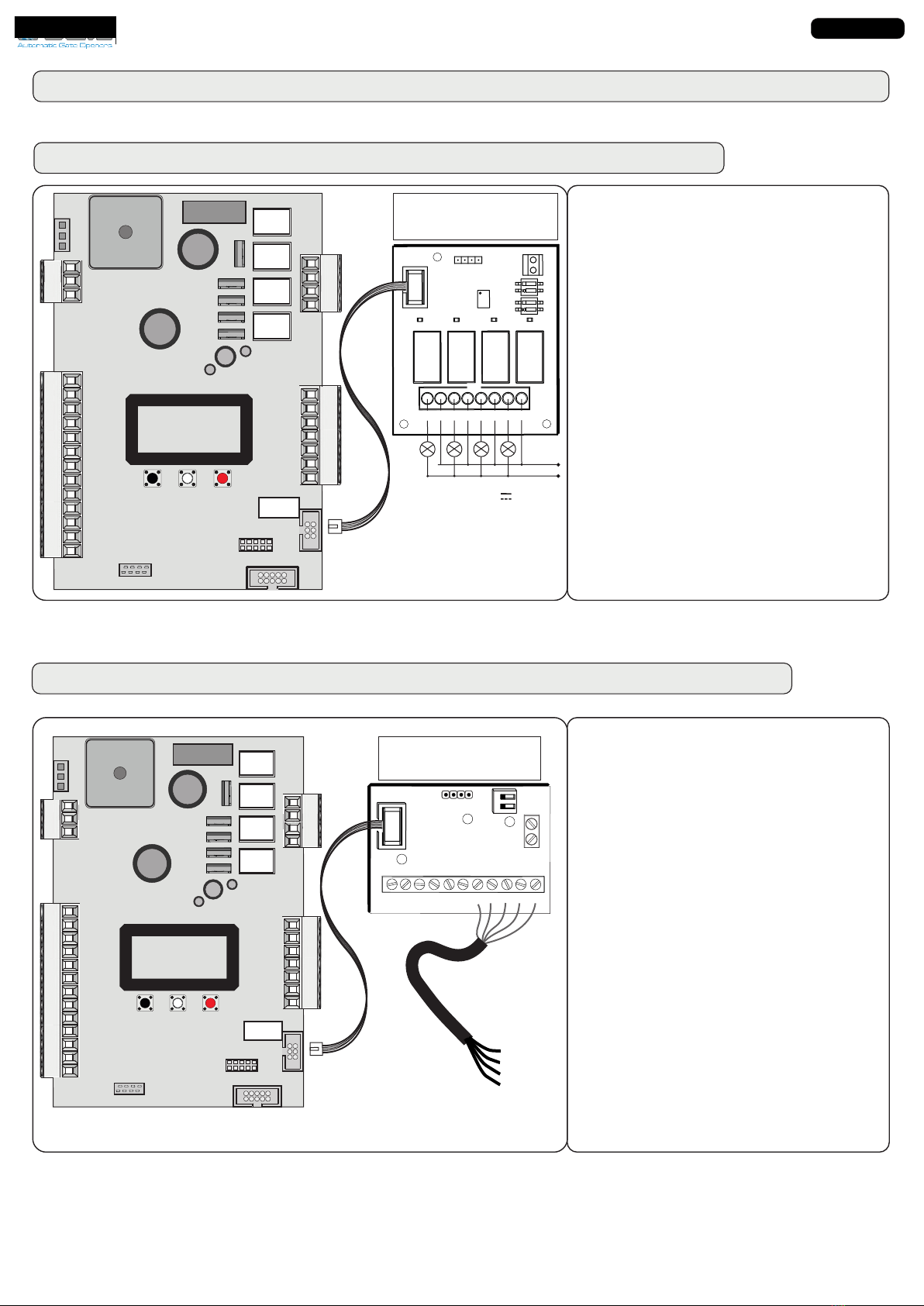
4. AU 24V INS ma 2mA
From men 424VAU or through the OLLY 3 it is possible to choose when to have voltage on the AU
output. In case of control units with batteries and/or photovoltaic panels, it is advisable to connect the
unused accessories (eg. Photocells) to the AU output and then configure the men 424VAU as
CC D TTT so it will be possible to save energ b lowering the power consumption in stand-
b and increasing the sstem autonom
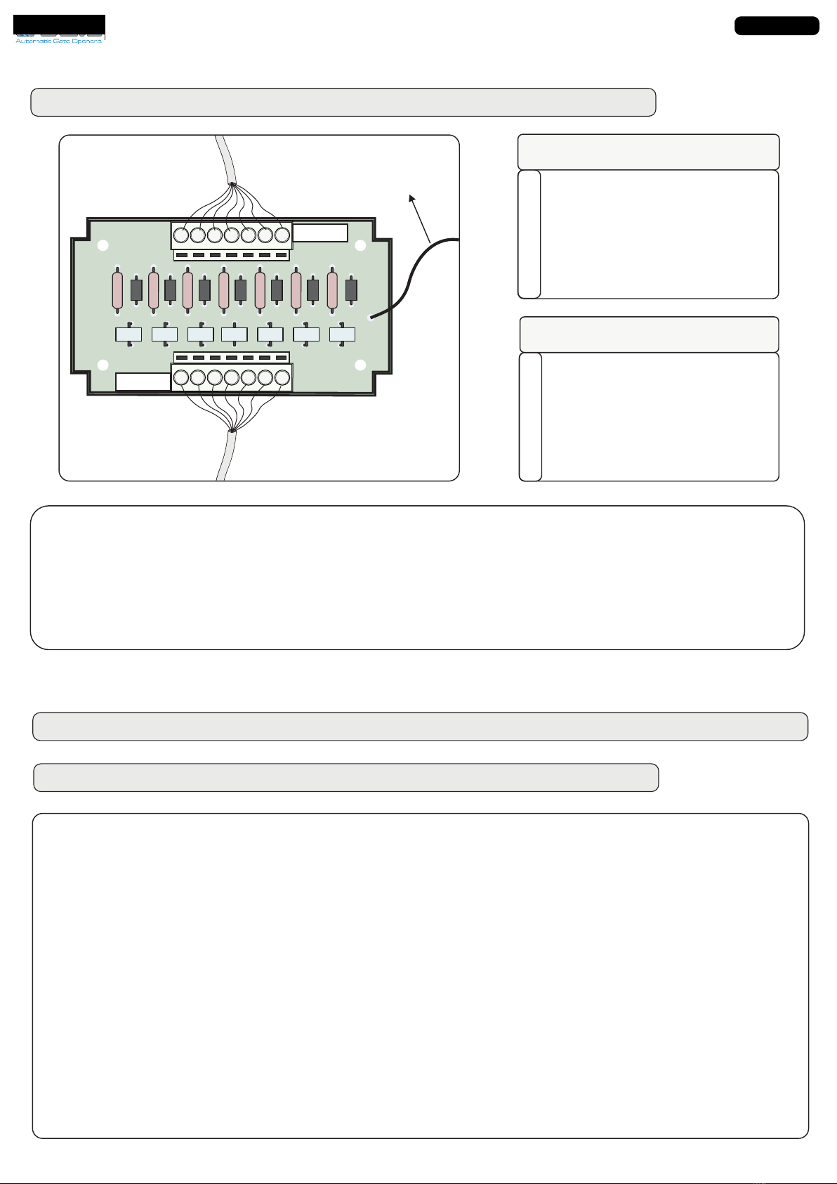
4. IMER N..
n clamp 4 artial penin Start or on clamp hotocell 2
It can be enabled through men2 or via OLLY 3. It opens and eeps the automation open until it
releases the contact. hen released, the operator will wait for the pause set then will close again
Note 1: If connected to the Partial Opening Start, this command will also be disabled on the remote control
Note 2: hen the timer is active, in the event of a safet intervention, a Start command will be required to
reset the movement
Note : In case of a power failure and with the gate open, if the TIMER is still active it will cause the gate
reclosing if no longer active, a new Start impulse will be required
taliano
ENGLIS
International registered trademark n. 804888