Manuel de l’opérateur
7
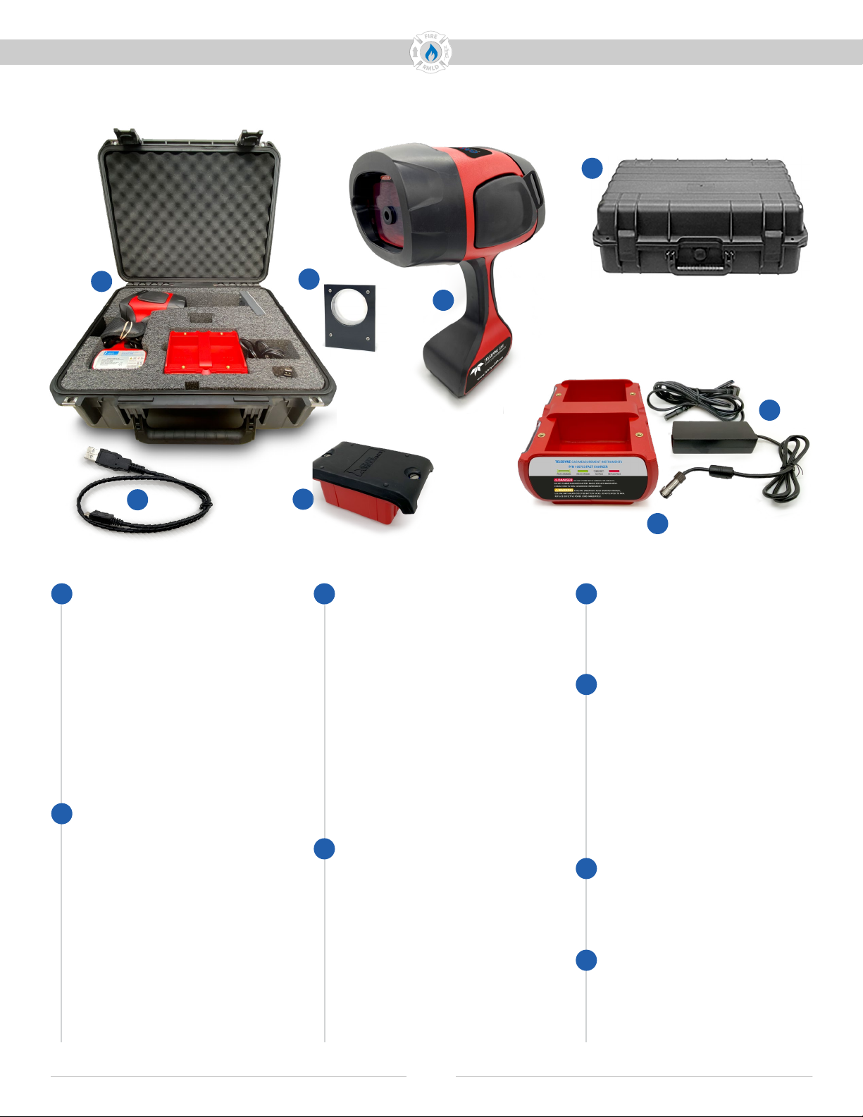
GAS LASER
Doc No. 16162 Rev A, GAS LASER Operator Manual © 2021 Teledyne Gas Measurement Instruments Ltd. All rights reserved.
Avertissements et dénitions
AVERTISSEMENT : N’utilisez
pas l’instrument dans des zones
dangereuses, à l’exception des
surfaces et des zones pour
lesquelles il est approuvé.
AVERTISSEMENT : Pour réduire
le risque d’inammation d’une
atmosphère inammable ou
explosive, les batteries doivent être
retirées, insérées et rechargées
uniquement dans un endroit
réputé non dangereux. Utilisez
uniquement un bloc-batterie
105756 remplaçable. Le chargeur
de batterie ne fait pas partie
de la certication de sécurité
dangereuse.
AVERTISSEMENT : Ne démontez
pas, n’ouvrez pas et ne modiez
pas cet instrument, y compris le
bloc-batterie 105756. Toutes les
réparations doivent être eectuées
uniquement par un établissement
agréé, comme indiqué dans ce
manuel.
AVERTISSEMENT : Ne démontez
pas, ne court-circuitez pas, ne
brûlez pas ou n’exposez pas à une
température élevée (≥60° C/140° F)
le bloc-batterie au lithium utilisé
avec cet instrument. Utilisez le
chargeur désigné pour charger la
batterie uniquement dans une zone
non dangereuse.
AVERTISSEMENT : Ne vous
connectez pas au port USB dans
une zone dangereuse. Connectez-
vous uniquement à un équipement
USB certié conforme aux normes
de sécurité appropriées telles que
IEC 61010-1 ou équivalent dans une
zone non dangereuse.
AVERTISSEMENT : La substitution
de composants peut nuire à
la sécurité intrinsèque. Aucun
composant réparable par
l’utilisateur n’est contenu dans cet
instrument.
AVERTISSEMENT
Informations sur les dangers, la sécurité et les avertissements
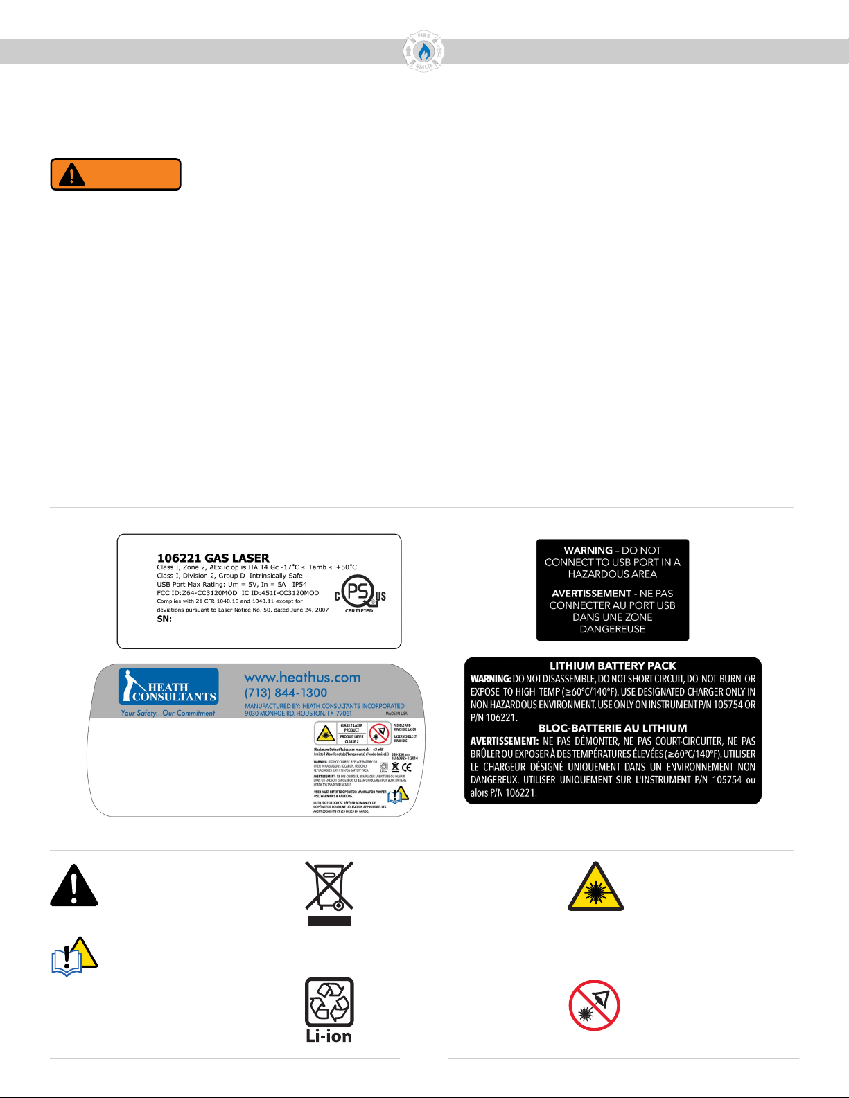
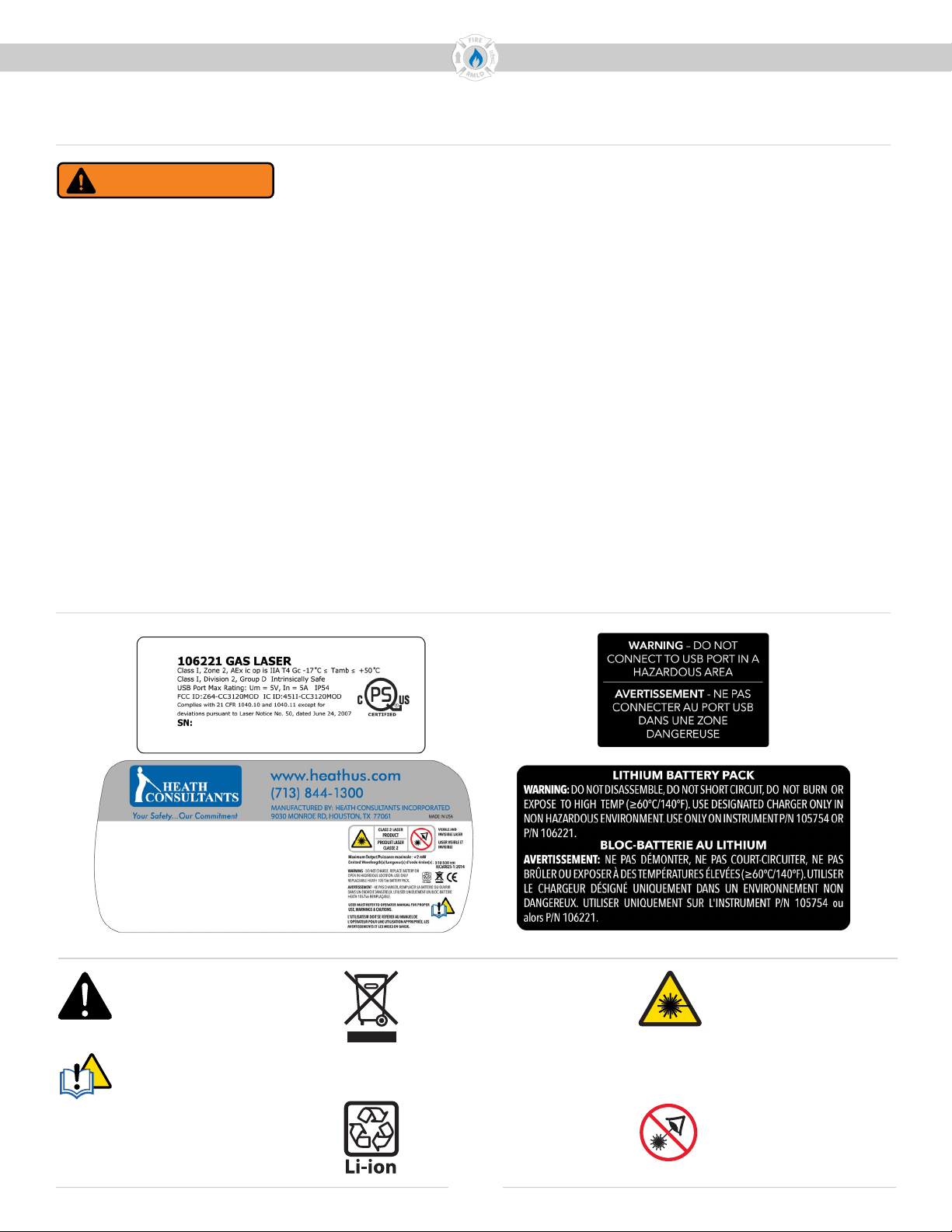
Étiquettes de sécurité sur l’instrument et le bloc-batterie
Symboles utilisés
Attention
Consulter le mode
d’emploi
Indice de protection
Ne jetez pas ce produit dans
le ux des déchets munic-
ipaux non triés. Jetez ce
produit conformément aux
réglementations locales.
Batterie au lithium-ion
Laser IR de mesure
Rayonnement :
Classe I Laser visible
(vert) Rayonnement :
Classe 2(II)
Ne pas xer le faisceau.
Éviter l’exposition directe
des yeux.
IP54