LEARN MODE
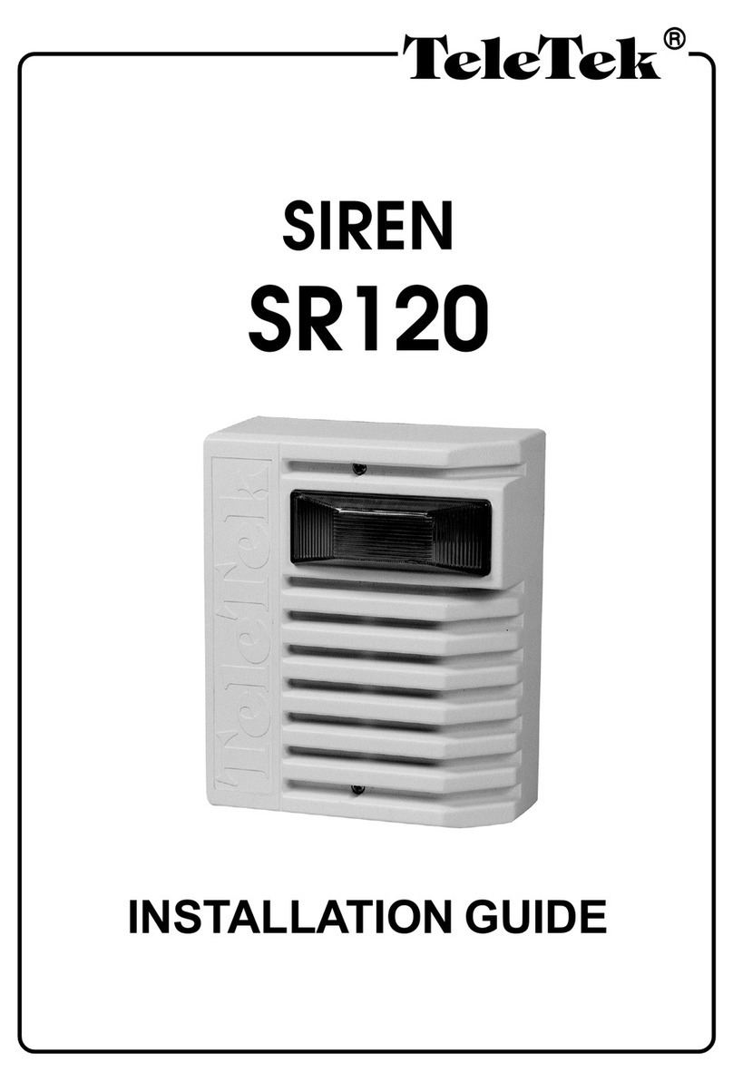
1. To set up a siren to the CM120R control module enter Learn Mode by
putting ON jumper LEARN and removing ExtSir and IntSir jumpers. Then put
ON the jumper that corresponds to the siren you wish to set up, i.e. ExtSir to
set up an external, OR IntSir—an internal siren. CM120R is in Learn Mode
now and the LED is blinking RED and short beep from the buzzer.
2. Put SR100TE/SR200R in Learn Mode. Power-up the SR100TE/SR200R.
The LED will blink fast in red for 5 seconds. During these 5 seconds close the
TAMPER of the siren 3 times.
3. SR100TE/SR200R will send identify itself to CM120R and after receiving
proper instructions will flash GREEN for half a second.
4. SR100TE/SR200R is set up now and will remain in RF-test mode until
Tamper is closed for longer than 5seconds.
5. To add another siren, change siren jumpers and repeat steps 2—4.
6. To exit Learn Mode remove the LEARN jumper.
7. Put the respective ExtSir or IntSir jumper on.
POWER OFF MODE
1. Power OFF state (with no power supply):
2. During the transportation or storage period SR100TE/SR200R should be in
Power-OFF state.
It is NOT necessary SR100TE/SR200R or CM120R to be set
up again, even after being in Power-OFF state for long time.
TEST MODE
Test the RF link between CM120R and SR100TE/SR200R in Test Mode.
1. To put CM120R in Test Mode and test the radio link simply remove the
LEARN jumper (if not already removed) and put on the TEST jumper. Make
sure the ExtSir (or IntSir) jumper is on.
SR100TE/SR200R (when in Test Mode) will indicate received data with 1 to 3
green flashes.
CM120R (when in Test Mode) will indicate every received message with 1 to 5
buzzer signals.
2. Send messages from the SR100TE/SR200R by closing the TAMPER
shortly and count the green flashes. Two or three flashes indicate a good RF-
link.
3. (Optional) Send ON/OFF messages from the CM120R by close/open the
Input and count the buzzer beeps. Three to five beeps stand for a good RF-
link. If the flashes and beeps are less than 2, it is necessary to mount the siren
in a different place.
4. To finish the tests put the siren cover back on. Make sure the TAMPER
switch is closed.
5. Remove the TEST jumper of the CM120R. The module is now in Operating
Mode and will work with SR100TE/SR200R depending on the ExtSir/IntSir
jumpers configuration.
OPERATING MODE
1. In this mode only ExtSir/IntSir jumpers are ON in a CM120R that is properly
connected to a control panel.
If some of the siren jumpers in the control module is off,
CM120R will behave as the corresponding siren is bypassed,
i.e. commands will not be send, nor will faults be generated.
However, messages from the siren will be acknowledged and
indicated.
2. If a LOW BATT message is received from a siren (outdoor or internal),
CM120R will switch the LOW BATT RELAY output regardless of the NC LBatt
jumper state. (see jumper configuration description).
3. If a TAMPER message is received from a siren (outdoor or internal),
CM120R will switch the TAMPER relay output regardless of the NC Tamp
jumper state (see jumper configuration description).
4. When two sirens (one outdoor and one internal) are used with one
CM120R, determine which one is in TAMPER or LOW BATT state by
removing the corresponding jumper (ExtSir for an outdoor and IntSir for an
internal siren). This will eliminate the event state (TAMPER or LOW BATT) of
the corresponding siren and will restore the relay.
5. Both sirens (SR200R/SR100TE) can work for at least one more month after
a LOW BATT event is detected.
6. To replace a siren battery, remove the old one and insert a new one after
opening the TAMPER. The LED will blink in red for 5 seconds. During this
period do not touch the TAMPER. After the LED stops blinking the siren will
enter RF Test Mode. Carry out the test and if the outcome is satisfactory,
mount the siren on the wall.
The set-up procedure needs NOT be repeated after battery
replacement.
TROUBLESHOOTING
1. CM120R
2. SR100TE/SR200R
Problem Indication Solution
Power is turned
on but the unit
does not work.
No short beep
from buzzer; the
LED does not
blink in red.
Make sure the module is properly
connected to the control panel.
The buzzer
beeps and the
LED blinks in
red every 3
seconds.
Make sure the siren battery is turned
on.
If the siren battery is on, check the
alarm panel for a LOW BATT
message.
If there is no LOW BATT message,
perform a new radio test in Test
Mode (see above).
The siren does
not sound when
the module is
activated.
No short buzzer
beep; the LED
does not blink in
red during
transmission.
Check the command module’s
connection to the alarm panel.
If the module is connected properly,
make sure the ExtSr/IntSr jumper is
on and the LEARN jumper is off.
TAMPER
message. Check whether the tamper is closed.
LOW BATT
message. Change the battery.
No indication on
the alarm panel
for a TAMPER
or LOW BATT
event.
Check the module relay output
connection to the alarm panel.
Where the relay outputs used are set
for an N.C. contact, make sure the
NC Tamp and NC LBatt jumpers are
on.
Problem Indication Solution
The siren does
not work when
the battery is
on.
No blinking red
LED indication for
5 seconds.
Check whether the battery is on.
The siren does
not sound.
No blinking red
LED indication. Make sure the ExtSr/IntSr jumper
on the CM120R module is on and
the LEARN jumper is off.
If the jumper configuration is
correct, a short buzzer beep and
the LED blinking in red every 3
seconds must indicate the CM120R
is activated.
With the CM120R on, carry out a
new radio test in Test Mode (see
above).
The siren does
not sound.
The LED blinks in
red. Check if the speaker is connected.
The siren
sounds, but
there is no
flash indication
(SR200R only).
The LED blinks in
red. The flash indication is out of order.
The siren does
not stop
sounding.
The LED blinks in
red. Make sure the CM120R command
module is properly turned on and
off by the alarm panel.
If the CM120R is properly turned on
and off repeat the radio test in Test
Mode.
