2023 © Copyright, Televés S.A.U.
Televes USA LLC. Norfolk Tech Center 16596 E. 2nd Avenue Aurora, CO 80011 televes.usa@televes.com www.televes.com
Safety Instructions:
LIGHTNING PROTECTION
Be sure the antenna system is grounded so as to provide
protection against voltage surges and built-up static charges.
Section 810 of the National Electrical Code ANSI/NFPA70, or
CSA C22.1 sections 10, 16, and 54, of the Canadian Electrical
Code, provide information with respect to proper grounding of
the mast and supporting structure, grounding of the antenna
lead-in wire to an antenna discharge unit, size of grounding
conductors, location of antenna-discharge unit, connection
to grounding electrodes, and requirements for the grounding
electrode (see gure and instructions).
Mount the lightning arrestor or 75 ohm coaxial grounding
block as close as possible to where the 75 ohm coaxial cable
down lead enters the house.
The ground wires for both the mast and the down lead should
be copper or aluminium wire, number eight (8) or larger.
The down lead wire from the antenna to the lightning arrestor
and the mast ground wire should be secured to the house,
spaced from four (4) to six (6) feet apart.
In the case of a“ground up”antenna installation it may not be
necessary to ground the mast if the mast extends four or more
feet in the earth. Consult a TV serviceman for the proper depth
in your location.
WARNINGS
To prevent re or shock hazard, do not expose the included
power supply to rain or moisture.
Installation of o-air antennas near power lines is dangerous.
For your safety, follow the installation instructions.
Any alteration or modication to the product or usage not in
accordance with product instructions voids the warranty.
Antenna Lead in Wire
Example of antenna grounding as per NEC (National
Electrical Code), ANSI/NFPA 70
Ground
clamp
Electric Service
Equipment
Ground clamps
Power service Grounding Electrode System
(NEC Art 250, Part H)
Antenna Discharge Unit
(NEC Section 810-20)
(May substitute a 75 ohm
Coax Grounding Block)
Grounding Conductors
(NEC Section 810-21)
High-VHF
Antenna Selector
This antenna provides optimal reception for the following zone(s)
UHF
See www.antennaweb.org for the list of broadcasters in each
reception zone where you live.
Technical specications of the intelligent
antenna (it must be powered)
Application example
Operating
band MHz
High VHF
174 - 216
CH7 - CH13
UHF
470 - 608
CH14 - CH36
Mode INTELLIGENT (BOSS ON)
Gain dBi 36 44
Output level Auto*
Power supply V 12
Consumption mA 70 (max) @12V
Wind load N 373 (@ 80 mph)
513 (@ 93 mph)
* The gain is automatically adjusted according to the level of
output.
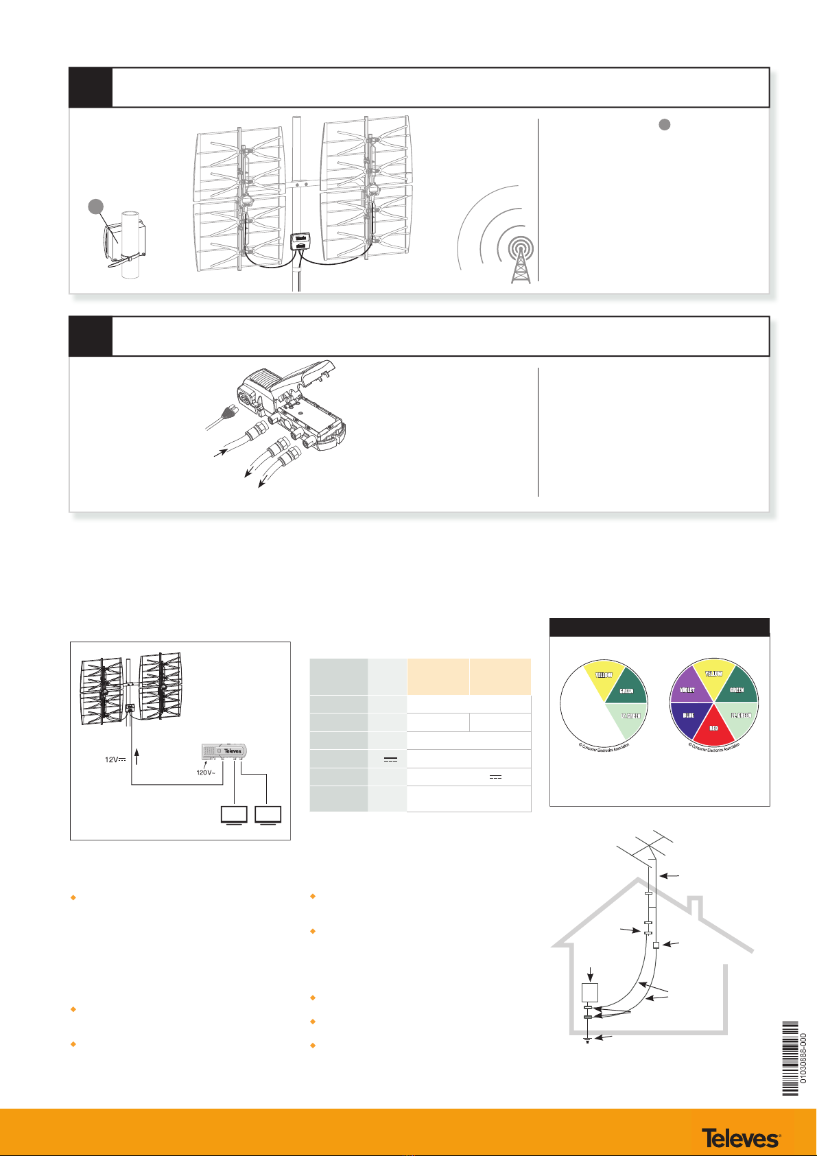
7
8
Fix the Mixer/Amplier Cbetween the two
antenna panels by using the provided tie.
Find the nal orientation to the TV transmitter
and rmly tighten all the elements.
Connect the included power supply to the
antenna using the leftmost connector (closest
to wall power) with an appropriate length of
75 ohm coax (RG-6 or larger is recommended).
Make sure than any device installed between
the power supply and the antenna, such
as a splitter, is DC power passing. The two
connectors on the right of the power supply
are for connecting your TV’s and/or coaxial
distribution.
FINAL NOTES:
- When aiming the antenna it may be necessary to alternate
adjustments between left and right several times in order
to achieve peak signal reception for the largest number of
desired channels.
- The antenna will work in an un-amplied, pass-through
mode, if the power supply is not connected or power
fails to reach the antenna for any reason. However, it is
recommended to always use the antenna with power
applied in order to activate the industry leading, TForce
automatic gain preamp.
- Always be sure to follow all local, state, and national electric
codes. Seek the assistance of a local professional if needed.
*(NOT included)
PSU 550104
Mains power
From mixer/amplier
To TV 1
To TV 2
P.S.U
Ref. 550104
(included)
*
*
*
BACK of Antenna
Aim this end
AWAY from TV
transmitting
towers
FRONT of Antenna
(“><” elements)
Aim this end
TOWARDS TV
transmitting
towers
C
TRANSMITTING
TOWER