Tendercare Snugseat Snappi User manual

Snugseat Snappi User Manual
Document No: 053-03 v11 Page 1 of 43 June 2015
Snugseat Snappi User Manual.doc
Snugseat Snappi
U
SER
M
ANUAL
This manual covers:
Nursery Snugseat on Size 1 Chassis
Junior Snugseat on Size 2 Chassis
IMPORTANT
Please read these instructions carefully
Before using the Wheelbase or Snug Seat

Snugseat Snappi User Manual
Document No: 053-03 v11 Page 2 of 43 June 2015
Snugseat Snappi User Manual.doc
Fig 0.1 Snugseat on Snappi Wheelbase (Nursery seat on
size 1 chassis shown)
Fig 0.2 Wheelbase(size 1 shown)

Snugseat Snappi User Manual
Document No: 053-03 v11 Page 3 of 43 June 2015
Snugseat Snappi User Manual.doc
Fig 0.3 Wheelbase Folded (size 1 shown)
Fig 0.4 Snugseat Seat Unit (Nursery shown)

Snugseat Snappi User Manual
Document No: 053-03 v11 Page 4 of 43 June 2015
Snugseat Snappi User Manual.doc
Item
Description
Page
1 Who to contact if you have difficulty 6
2 Introduction 6 – 7
3 Unpacking 7 – 8
4 Preparing the wheelbase for use 8 - 17
4.1.1 Unfolding the frame (Original Locks) 8-9
4.1.2 Unfolding the frame (Spring Loaded Locks) 10
4.2A Original Brakes (pushchairs supplied before June 2015) 11
4.2B Pin Brake (pushchairs supplied after June 2015) 11 – 12
4.2C Tyres 12
4.3 Fitting seat to the chassis and setting safety catch 13– 15
4.4 Tilt in space 16
4.5 Fitting footrest to seat 17
4.6 Fitting pommel to seat 18
5 Setting up the seat unit 19 – 24
5.1 Fitting support pads 20 – 22
5.2 Setting up the patterned cover 22 – 23
5.3 Adjusting the harness 24
5.4 To lock and release the harness 24
5.5 Final checks 24
6 Accessories 25 – 33
6.1 Shopping Basket 25
6.2 Equipment Carrying Tray 26
6.3 Sun Canopy 27– 28
6.4 Frame Padding 28
6.5 Rain Cover 29
6.6 Playtray 30 – 33
6.7 Vertical Cylinder Carrier 33 – 34
7 User instructions 35
7.1 Getting into the Snugseat 35
7.2 Setting out of the Snugseat 35
8 Attendant Pushing 35
8.1 Pushing 35 – 36
8.2 Brakes 36
8.3 Comfort 36

Snugseat Snappi User Manual
Document No: 053-03 v11 Page 5 of 43 June 2015
Snugseat Snappi User Manual.doc
8.4 Lifting and general safety 36 – 37
9 Cleaning 37
9.1 Chassis and seat shell 37
9.2 Patterned covers and tummy pad 37
9.3 Modular foam pads 37
9.4 5-Point harness 37
10 Maintenance 38
10.1 Routine maintenance 38
10.2 Six – monthly maintenance 38 – 39
11 Oxygen Cylinder 39
12 Warranty 40
13 Transporting the Snugseat Snappi 40
13.1 Preparing wheelbase for transport 41
13.2 Attaching wheelbase to vehicle 41 – 42
14 Repairs 43

Snugseat Snappi User Manual
Document No: 053-03 v11 Page 6 of 43 June 2015
Snugseat Snappi User Manual.doc
1: Who to contact in difficulty
Tendercare Ltd.
PO BOX 3091, Littlehampton, BN16 2WF
Tel: (01903) 726161 Fax: (01903) 734083
Email: [email protected]
Web: www.tendercareltd.com
2: Introduction
The Snugseat postural control seating system is designed to enhance the sitting of
disabled children who have postural instability with minimal skeletal deformities.
The Wheelbase is made of a strong and lightweight aluminium alloy, minimising weight
and providing a very rugged frame. The wheelbase provides a tilt in space facility and has
2 fixed rear wheels and 2 castor wheels at the front for easy steering. The wheelbase
comes in 2 sizes, size 1 and size 2 and can accommodate nursery or junior snug seats
respectively.
The seat unit is available in two sizes, Nursery and Junior. The seat is supplied with an
attractive cover and modular pad inserts to meet the needs of a wide range of users. The
seat has five-point harness, pommel and footrest. The seat can be quickly fitted and
removed from the buggy, which can be folded for transport. The complete system has
passed impact tests and has been designed for use as a vehicle seat when restrained in
accordance with this manual (see section 12).
The following accessories for use with the Snugseat Snappi are available from Tendercare
Ltd. Carrying tray, Shopping basket, Rain-hood, Sun canopy, Snug-toes, Standard
Headrest, Occipital Roll Headrest and Extra Recess Headrest.
These instructions apply to all sizes.
MODEL MAX OCCUPANT
WEIGHT SEAT SIZE
– mm
WIDTH DEPTH HEIGHT
Nursery 40 kg 300 250 550
Junior 40 kg 340 320 610
IMPORTANT:
Maximum weight includes the occupant and all accessories.

Snugseat Snappi User Manual
Document No: 053-03 v11 Page 7 of 43 June 2015
Snugseat Snappi User Manual.doc
Dimensions (mm)
Snugseat Snappi Ope
n
Size 1 Size 2
A 950 1065
B 571 684
C 1000 1055
All sizes and weights are given as a guide. Tendercare ltd reserves the right to amend
specifications at any time as part of their product development programme.
3: Unpacking
The wheelbase is delivered in a cardboard carton. This measures 680mm wide x 480mm
deep x 1030mm high and weighs approximately 15Kg.
The Snugseat seat unit, upholstery and modular padding are delivered in a cardboard
carton of approximate weight 13kg and size 480 mm wide x 530 mm deep x 800 mm high.
WARNING:
The transit carton is quite bulky so moving and unpacking must be done with care.
Observe all lifting and handling regulations.
Stand the carton upright making sure it is supported and cannot fall over. Open the carton
and remove any packages or packing, which could obstruct the removal of the wheelbase.
Remove the wheelbase or seat and any other packages, which are still in the carton.
Snugseat Snappi User Manual
Document No: 053-03 v11 Page 8 of 43 June 2015
Snugseat Snappi User Manual.doc
Check you have the following items:
Item
Component
Number
Yes
No
1. Buggy 1
2. Seat Unit 1
3. 5 point harness fitted to seat unit 1
4. Footrest 1
5. Pommel 1
6. Bag containing seat cover, tummy pad and pommel cover 1
7. Bag containing modular pads and wedges 1
8. User Manual 1
IMPORTANT:
If any items are damaged or missing, then please contact Tendercare, preferably by email at
info@tendercareltd.com or alternatively please call us on (01903) 726161 within 36 hours of
delivery.
Remove the upholstery and modular pads from their plastic bags and any protective
packaging from the frame. After unpacking and checking you have all components and
they are in good condition dispose of the packaging at your local recycling centre.
Alternatively retain and reuse.
4: Preparing the wheelbase for use
WARNING:
When opening or folding the wheelbase, ensure that you hold the frame so that you
avoid any danger of catching your fingers in moving parts.
Keep children clear of the wheelbase during opening and folding.
4.1.1 Unfolding the Frame (original locks)
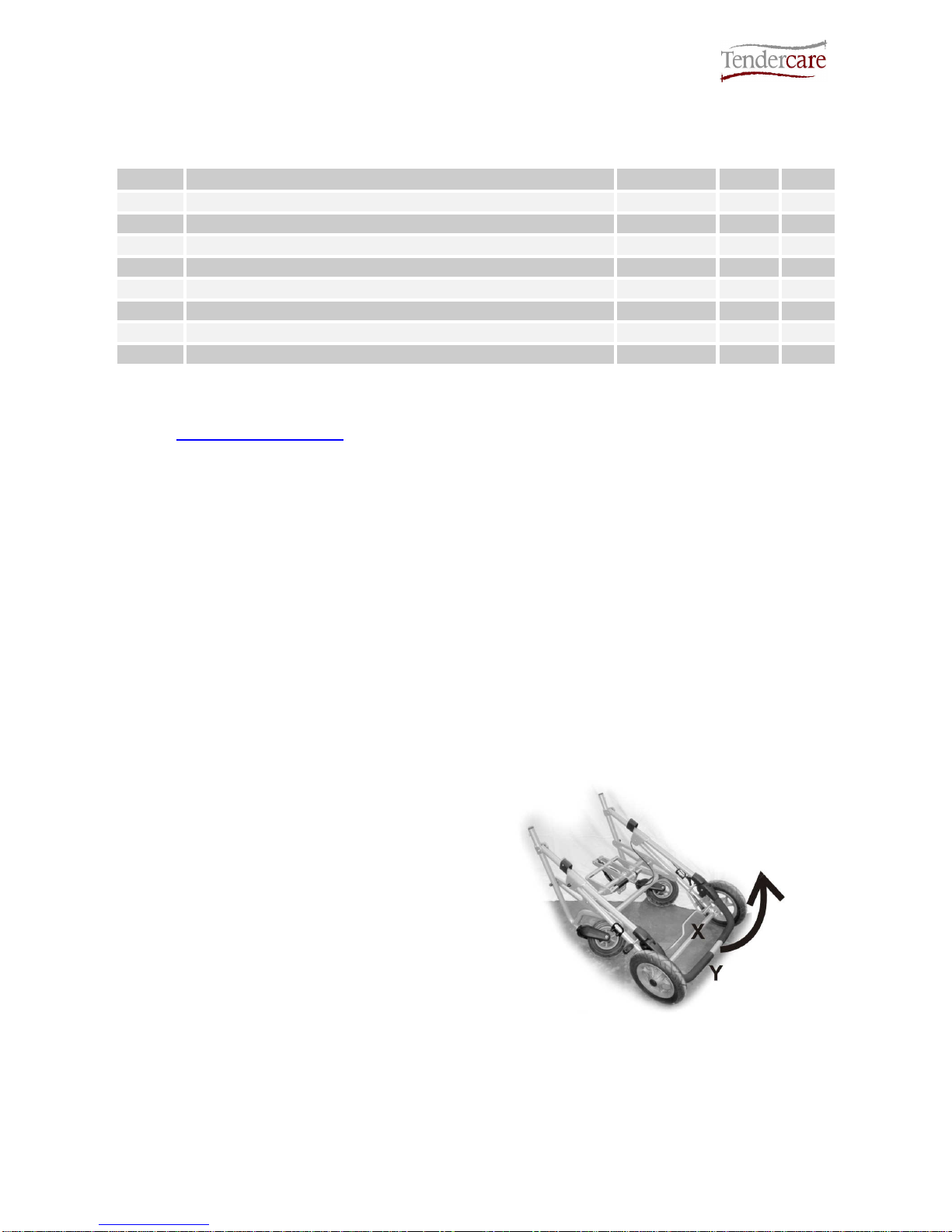
Standing at back of the wheelbase,
place your foot on the rear cross
member X (see right) and lift handle
labelled Y as far as it will move.
This will open the frame.
Fig 4.1.1.1
Snugseat Snappi User Manual
Document No: 053-03 v11 Page 9 of 43 June 2015
Snugseat Snappi User Manual.doc
Fig 4.1.1.2
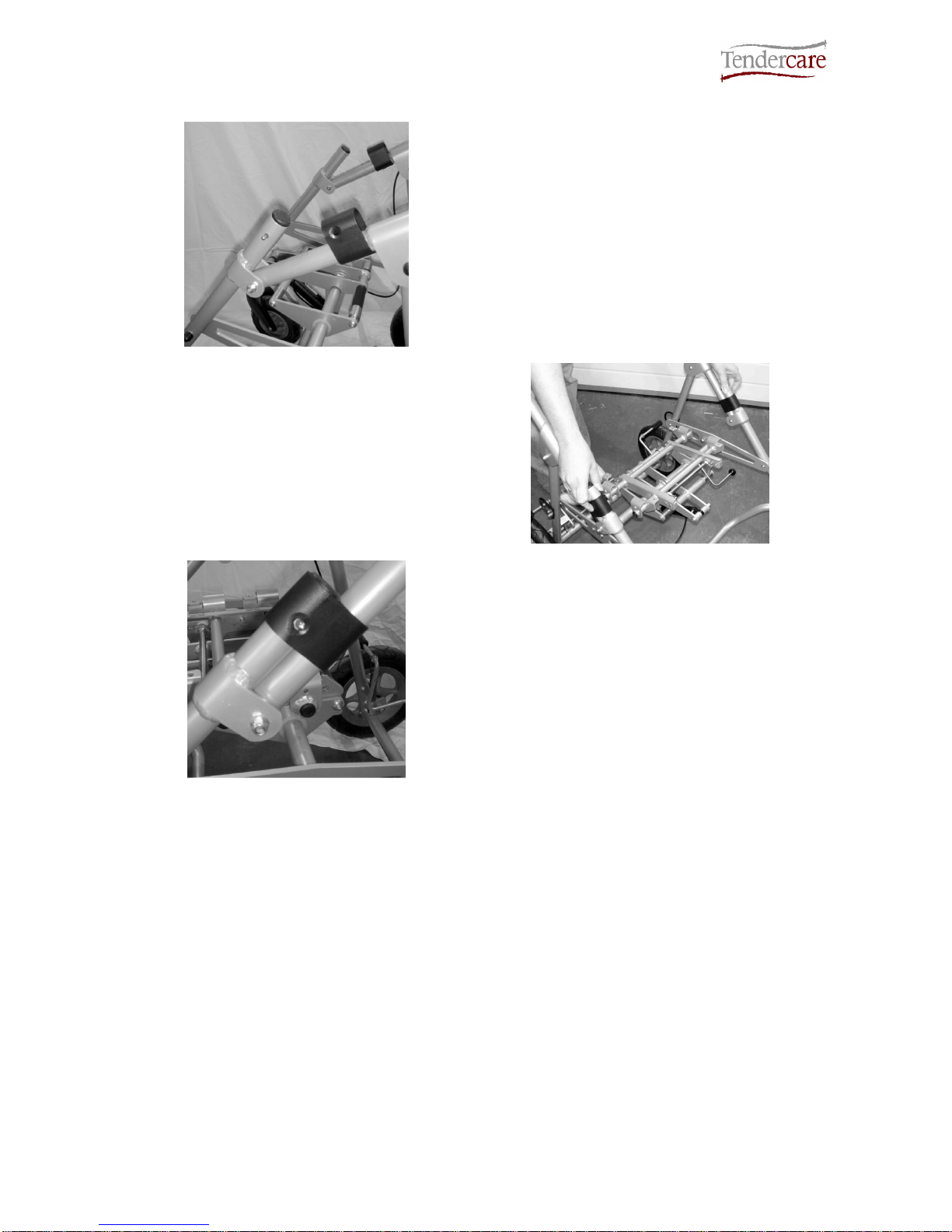
Next locate the 2 plastic locking sliders.
These will be stowed in the “open” position
and are held in place by 2 small spring clips.
Press the 2 silver “Spring pins” in and
slide the 2 locking pieces down over the
lower tube sections.
Fig 4.1.1.3
Fig 4.1.1.4
The pins will spring through the holes in the
sliders and hold them in place (see left).
WARNING:
If the locking sliders are not in the correct position, or the spring pins do not
protrude thereby allowing the locking clips to move back up the frame, then the
frame may collapse in use.
Folding the wheelbase: To unlock the frame and fold the wheelbase, reverse the above
instructions.
Snugseat Snappi User Manual
Document No: 053-03 v11 Page 10 of 43 June 2015
Snugseat Snappi User Manual.doc
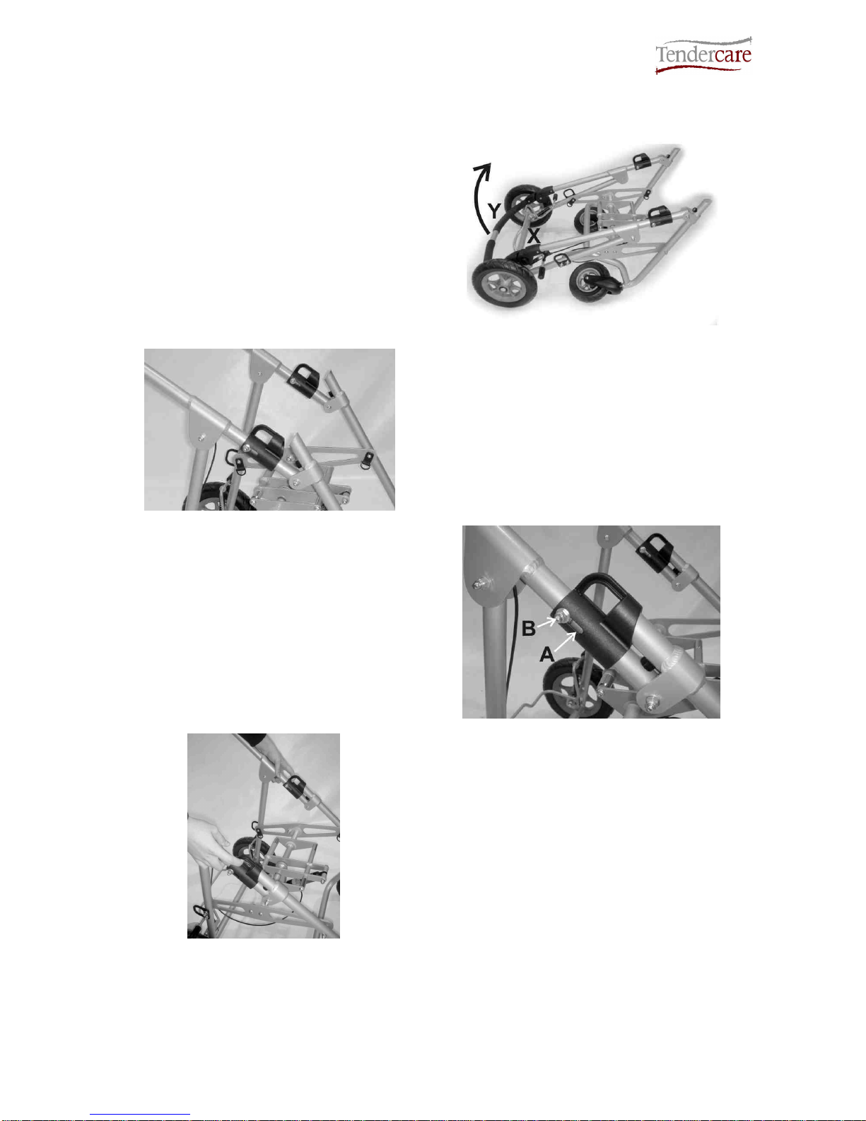
4.1.2 Unfolding the Frame (Spring loaded locks)
Standing at back of the wheelbase,
place your foot on the rear cross
member X (see right) and lift handle
labelled Y as far as it will move.
This will open the frame.
Fig 4.1.2.1
Fig 4.1.2.2
Once the frame is almost open, the 2 plastic
frame locks will engage with the angled
sections of the lower frame.
Continue to unfold the frame; this will force
the locks up the tubes. There will be some
resistance, as you will be working against the
locking springs.
Once fully open, the frame locks will
snap shut over the front frame, securing
the frame in the open position.
Always check that both locks are fully
closed. In the locked position the guide
bolt ‘B’ will be sat in the top of the slot ‘A’
on the side of the slider as shown (see
right). If there is any slot visible above
the guide bolt, push the lock down by
hand until it will not move any further.
Fig 4.1.2.3
Fig 4.1.2.4
To fold the frame:
Standing beside the frame, pull up the 2
locking sliders as shown (see left).
Whilst holding the locks open, push down
with your arm on the upper frame or push
handle, so that the frame starts to fold.
Release the locking sliders, and fold down
the frame by moving the push handle down
as far as it will move.
IMPORTANT:
Always check that BOTH frame locks are fully closed before using the frame. If they
are not properly engaged, the frame could collapse during use.
Snugseat Snappi User Manual
Document No: 053-03 v11 Page 11 of 43 June 2015
Snugseat Snappi User Manual.doc
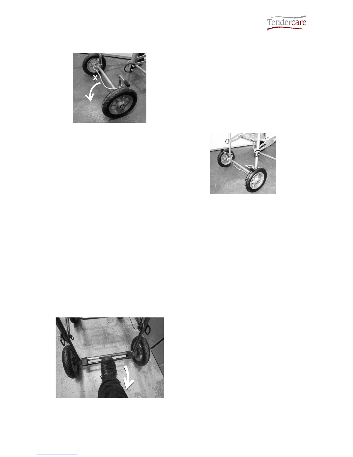
4.2A Original Brakes (pushchairs supplied before June 2015)
Fig 4.2.1
To apply the brake, put your foot on the top
of brake bar (labelled X) and push down as
shown. The brake will flip down onto the
wheels and lock them.
To release the break, simply hook your foot
between the middle raised portion of the
brake bar, and the frame cross bar. Then,
lift the break bar with your foot until it flips
back and stops against the brake stop pins.
You may find it easier to use your hand
instead of your foot to release the brake. If
operating the brake by hand always hold the
brake by the raised section in the middle of
the bar.
Fig 4.2.2
WARNING:
The break mechanism is spring loaded so care must be taken when operating it.
When operating the brake mechanism ensure that you always keep a firm hold of
the pushchair, keeping your hands well away from the brake mechanism.
Always put the brake on when placing the child in or taking them out of the seat.
Do not leave the pushchair on a slope, even with the brake on. Always ensure that
the pushchair is on level ground to prevent risk of injury to the occupant.
Do not leave the brake on when the pushchair is not in use as this will damage the
rear wheels.
4.2B Pin Brake (pushchairs supplied after June 2015)
Fig 4.2.3
Snappi Pushchairs supplied after June 2015
will be fitted with the new Pin Brake
mechanism.
To set the pin brake, first securely hold the
push handle. Place your foot on the top of
the push bar as shown (see Fig 4.2.3, left)
then press the bar down as far as it will go.
If the brake is stiff, try rolling the pushchair
forward slightly to help line up the pins with
the locking rings on the wheels.

Snugseat Snappi User Manual
Document No: 053-03 v11 Page 12 of 43 June 2015
Snugseat Snappi User Manual.doc
Fig 4.2.4 Right: The brake in the fully locked
position.
Fig 4.2.4
Fig 4.2.5
To release the pin brake, hold the pushchair
and place your foot underneath the brake
bar as shown (see Fig 4.2.5, left). Lift the
bar as far as it will move to ensure the pins
are clear of the locking rings.
Warning:
When operating the brake mechanism ensure that you always keep a firm hold of
the pushchair and keep your hands well away from the brake mechanism.
Do not leave the pushchair on a slope, even with the brake on. Always ensure that
the pushchair is on level ground to prevent risk of injury to the occupant.
4.2C Tyres:
As standard the Snugeat Snappi pushchair is supplied with solid tyres, however pneumatic
tyres are also available as an option. If your pushchair is supplied with pneumatic tyres
these need to be regularly checked and inflated if necessary using a hand or foot pump.
The operating pressure for the tyres is 36 PSI (note: do not inflate the tyres above 36 PSI).
Do not use high pressure air lines or mechanical pumps as used in garages to inflate the
tyres.
Snugseat Snappi User Manual
Document No: 053-03 v11 Page 13 of 43 June 2015
Snugseat Snappi User Manual.doc
4.3 Fitting the seat to the chassis
The seat is fitted with a Snappi Interface system, and includes a 2-stage latch that
comprises a main latch and a second safety catch that prevents accidental release of the
seat from the chassis.
The safety catch must be correctly set before the main catch can be operated:
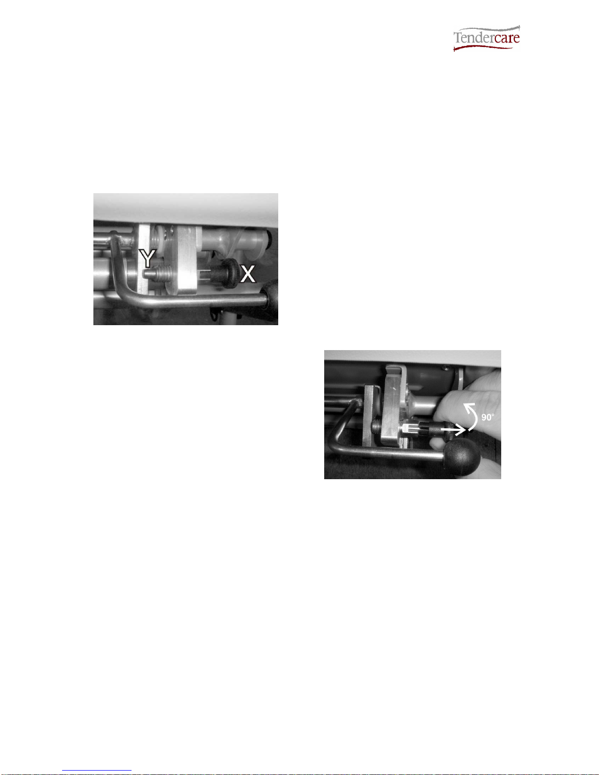
How to operate the safety catch:
Fig 4.3.1
Safety Catch Locked
The safety catch clip is located under the
front right corner of the seat near to the
release lever.
Definition of components:
X: Pull handle
Y: Locking Pin
To release it, pull the handle “X”, and turn it
90 degrees so that the pin “Y” is fully
retracted.
To lock it, pull “X” and turn 90 degrees in
the opposite direction, so that pin “Y” is fully
protruded and sits behind the interface main
catch “B” (see fig 4.3.3 on next page).
Fig 4.3.2
Safety Catch unlocked
Important:
When fitting or removing the seat, the carer / parent must first ensure that the safety
catch pin is set in the “unlocked” position. It will not be possible to fit or remove the
seat if the latch is “locked”, and attempting to do so may cause damage to the
chassis or the seat.
Once the seat has been fitted, the carer / parent must always lock the safety catch.
Note:
A warning label is positioned on the front right hand portion of the tilt frame on the
chassis, to remind carers to lock the safety catch.
Snugseat Snappi User Manual
Document No: 053-03 v11 Page 14 of 43 June 2015
Snugseat Snappi User Manual.doc
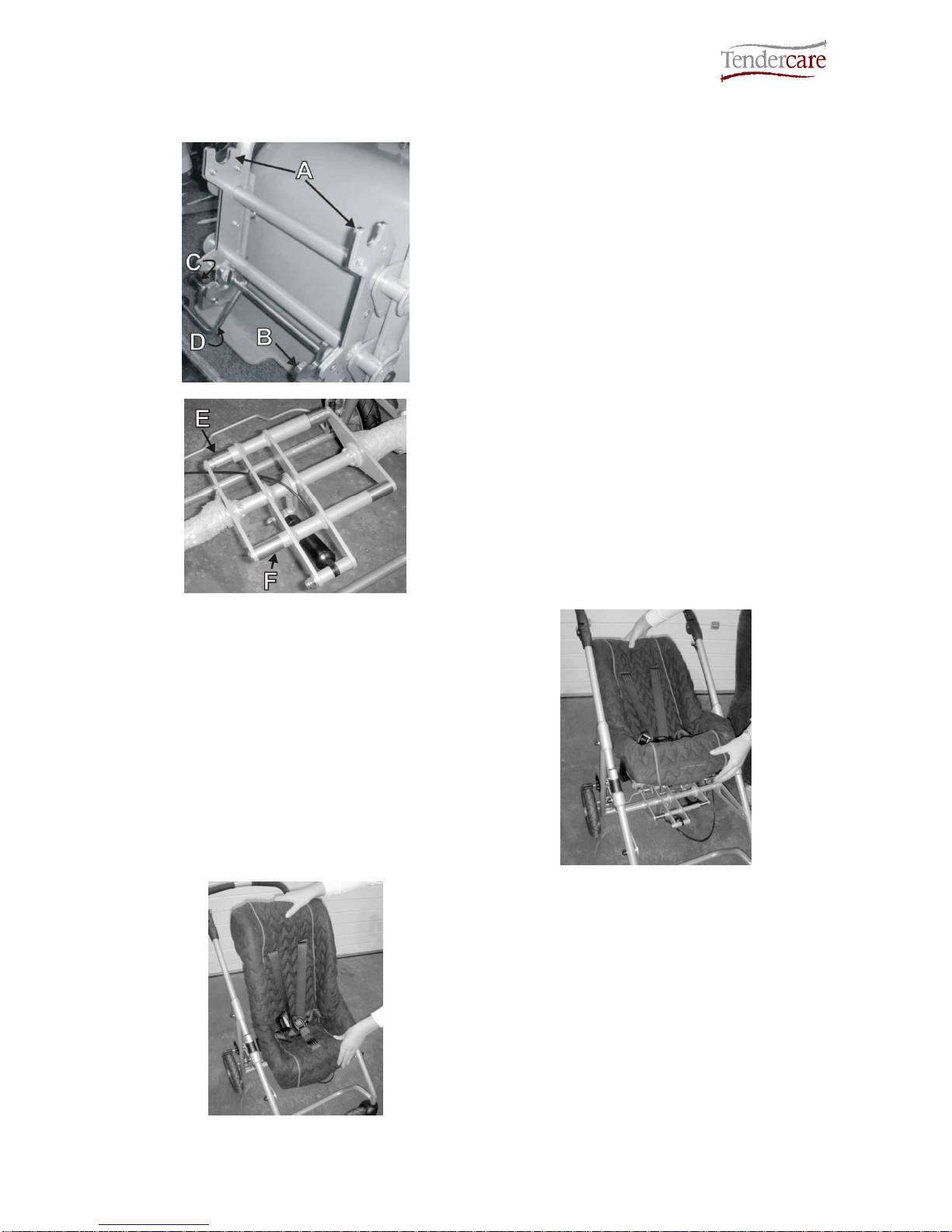
To fit the seat to the frame:
Fig 4.3.3
Fig 4.3.4
Definition of interface mounting points:
A: Interface Rear Hooks
B: Interface Main Clips
C: Interface Secondary Latch
D: Interface Release Handle
E: Frame interface rear bushings
F: Frame interface front bushings
Ensure that the secondary latch “C” has
been unlocked (see instructions on previous
page).
Holding the seat as shown, tilt it back and
locate the 2 rear hooks “A” on the back of
the interface, over the stainless steel
bushings on the back of the frame interface.
Fig 4.3.5
Fig 4.3.6
Next, rotate the seat forward and down so
that the main clips “B” snap over the front
stainless steel bushes on the frame
interface.
Note that due to the design of the frame
interface, it is not possible to fit the seat
backwards. If fitted the wrong way around
the clips will not close and it will not sit down
into the frame.

Snugseat Snappi User Manual
Document No: 053-03 v11 Page 15 of 43 June 2015
Snugseat Snappi User Manual.doc
Next, push down firmly on the release lever
“D” to ensure that the clips are fully closed.
Note the lever is positioned under the front
right corner of the seat (see right).
Set the secondary latch “C” to the “Locked”
position (so that the pin sits behind the
interface clip).
Fig 4.3.7
Fig 4.3.8
To remove the seat, first unlock the
secondary catch “C” as detailed on page 11.
Lift the release lever “D” up, whilst holding
the top of the seat with your other hand.
This will open the main clips “B”, rotate the
seat back so that the main clips are clear
from the frame, and lift the seat away from
the buggy.
IMPORTANT:
Always ensure that the seat interface clips are fully closed. To test this, press down on the
release lever when fitted and make sure the clips will not move (see fig 4.3.5).
Always lock the secondary latch before using the buggy.
Always unlock the secondary latch before fitting or removing the seat. Attempting to fit or
remove the seat with the latch locked could cause damage to the seat, interface or chassis.
Do not attempt to fit the seat backwards. It will not lock in a rearward facing position.
The seat interface system is spring loaded, so ensure your fingers are clear of the clips when
fitting or removing.

Snugseat Snappi User Manual
Document No: 053-03 v11 Page 16 of 43 June 2015
Snugseat Snappi User Manual.doc
4.4 Using the Tilt in Space facility
Fig 4.4.1
To operate the tilt in space mechanism,
place your hand over the push handle
adjustor, and lift the lever ‘L’ (see left) as
shown.
This will open the gas strut and tilt the seat.
Note; The speed of tilt can be controlled by
varying the pressure applied at lever L.
Use your other hand to support seat as it
tilts.
Fig 4.4.2
Fig 4.4.3
To reset the tilt mechanism, hold down lever
L and push down firmly on the front of the
seat as shown (see left). Once in the
desired position, release lever L. For a 90-
degree position, move the seat so the gas
strut is fully closed and it will not move any
further before releasing the tilt lever.
IMPORTANT:
Always ensure any harness provided for the child is used and correctly adjusted before
reclining or returning the seat to a more upright position.
Always support the seat when tilting, as the gas springs can be quick to operate. If the seat is
not supported, is may move swiftly and could cause the occupant distress.

Snugseat Snappi User Manual
Document No: 053-03 v11 Page 17 of 43 June 2015
Snugseat Snappi User Manual.doc
4.5 Fitting footrest to seat
Fig 4.5.1
NOTE: - The seat cover is not shown for
clarity.
Pass the two chrome bars “A” of the footrest
through the buttonhole in the front of the
seat cover and insert them into the
corresponding holes in the seat frame. (See
picture opposite)
Lock footrest in place by tightening (turn
clockwise) the two thumbscrews “B” under
the seat frame.
To adjust the height of the footrest, loosen
the two screws “C” in the centre of the
footrest. (See picture opposite). Turn the
screws anticlockwise using a flat bladed
screwdriver whilst holding the nut at the
back of the footrest with a 10mm spanner.
Move the footrest to the desired height and
retighten both screws (turn clockwise).
The foot straps “D” are held with Velcro. To
fit and adjust simply pull them apart place
around the feet and push together.
Fig 4.5.2
Snugseat Snappi User Manual
Document No: 053-03 v11 Page 18 of 43 June 2015
Snugseat Snappi User Manual.doc
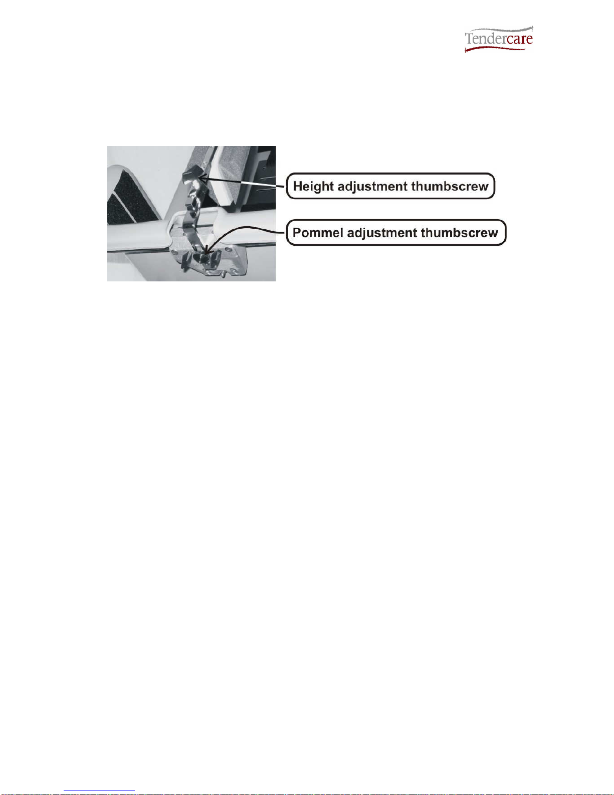
4.6 Fitting pommel to seat
The pommel is mounted on an adjustable steel frame so that the height and depth can be
adjusted using thumbscrews. (See picture below).
To fit the pommel, pass the chrome bar with a slot in it through the buttonhole in the front
of the seat cover. Then looking under the front of the seat, remove the thumbscrew shown
in the picture above. Insert the slotted bar of the pommel into the mounting slot then insert
and tighten the thumbscrew.
NOTE: - The seat cover is not shown for clarity.
To adjust the depth, loosen the thumbscrew under the seat and move the pommel in or out
until it is in the desired position then retighten the screw.
To adjust height, loosen the thumbscrew on the front of the pommel support tube. Move
the pommel to the desired height then retighten the screw making sure that the screw fits
into one of the indentations in the pommel support bar.
IMPORTANT: - DO NOT use the pommel as a stop to prevent the child sliding
forwards.
Snugseat Snappi User Manual
Document No: 053-03 v11 Page 19 of 43 June 2015
Snugseat Snappi User Manual.doc
5.0 Setting up the seat unit
When setting up the seat unit always ensure the following is done: -
•Always consult your Therapist or Rehabilitation Engineer for advice.
•Ensure that the child is relaxed and happy and if possible in an environment in
which they are familiar.
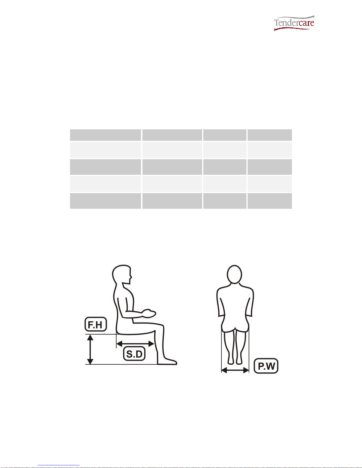
•If possible, sit the child on a plinth to take the measurements listed below:
Note: you can now position the pads according to the child’s dimensions
Measurement Symbol Millimetres Inches
Pelvic Width P.W.
Seat Depth S.D.
Lateral Trunk Support
(Under armpit to seat) LTS
Footrest Height F.H.

Snugseat Snappi User Manual
Document No: 053-03 v11 Page 20 of 43 June 2015
Snugseat Snappi User Manual.doc
5.1 Fitting support pads
For an example of pad positioning see fig 5.1.1.
Select the correct seat cushion and Velcro it into the seat shell, so that the front of the
cushion is flush with the front edge of the shell. The flat cushion gives a neutral hip angle
and the ramped cushion will achieve a flexed hip angle.
Select the combination of back pads required to give the required set seat depth (S.D.)
and Velcro in position.
Using the pelvic width (P.W.) and lateral trunk support (L.T.S.) dimensions position the
pads in the shell.
Adjust footplate to the required height (F.H.) See section 4.5.
Check the following: -
•The pelvis is in the mid line position and not anteriorly rotated (i.e. not sacral
seating)
•The pelvic lateral supports provide enough support without being over tight.
•The lateral supports are not too tight under the arm pits
•The hips are about the mid line
•The footrest is adjusted to the correct height
•The abduction is satisfactory. If more abduction is required fit a pommel. (See
section 4.6).
IMPORTANT: - DO NOT use the pommel as a stop to prevent the child sliding
forwards.
Other manuals for Snugseat Snappi
2
Table of contents
Other Tendercare Stroller manuals

Tendercare
Tendercare Snugseat Snappi User manual

Tendercare
Tendercare Nursery Snugseat Spring User manual

Tendercare
Tendercare Cloud Instruction manual

Tendercare
Tendercare Snappi Pushchair User manual

Tendercare
Tendercare Swirl User manual

Tendercare
Tendercare Snappi Pushchair Instruction manual

Tendercare
Tendercare Snazzi Instruction manual

Tendercare
Tendercare Snazzi Pushchair User manual

Tendercare
Tendercare Snappi Seat User manual

Tendercare
Tendercare Snapi Pushchair User manual


