Tendercare Snappi Seat User manual

Snappi Seat Standalone User Manual
Document No: 053-07 v5 Page 1 of 54 January 2019
Snappi Seat Standalone User Manual.doc
Snappi Seat
USER MANUAL
This manual covers:
Size 1 and 2 Snappi Seats (standalone)
IMPORTANT
Please read these instructions carefully before using the
Snappi Seat
This manual covers setting up and working with the seating system
when supplied standalone with a different chassis. This manual
should be used in conjunction with the manual supplied with the
chassis. If you have a Snappi Pushchair, please refer to the Snappi
Pushchair user manual, which covers both the Snappi Chassis and
Seat.
My Snappi Seat Serial Numbers:
TEN/SC……….
TEN/SS…….....
Snappi Seat Standalone User Manual
Document No: 053-07 v5 Page 2 of 54 January 2019
Snappi Seat Standalone User Manual.doc
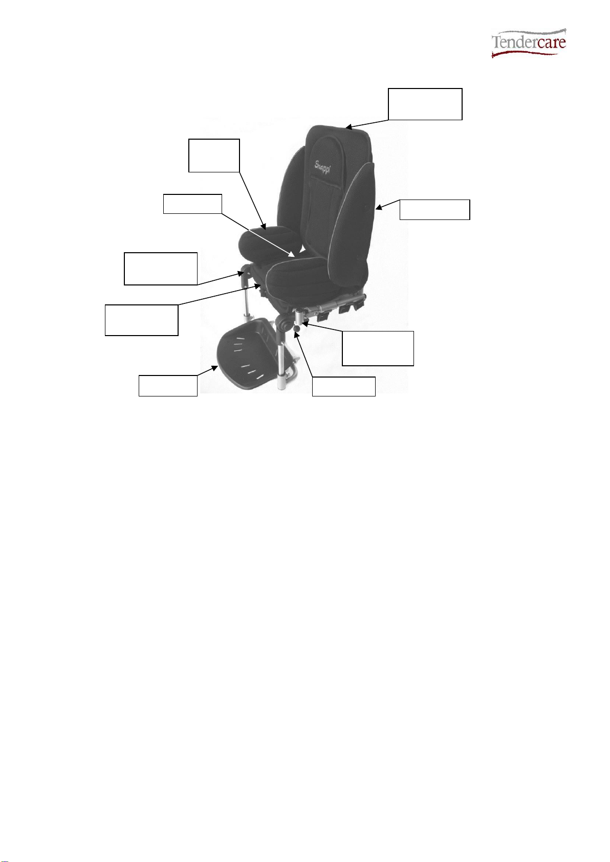
Fig 0.1 Snappi Seat (Size 1 shown)
Adjustable
Back
Hip
Guides
Side Pads
Interface
Playtray
Mountings
Footrest
Adjustable
Base
Knee Angle
Adjustors
Hip Belt

Snappi Seat Standalone User Manual
Document No: 053-07 v5 Page 3 of 54 January 2019
Snappi Seat Standalone User Manual.doc
Item
Description
Page
1
Who to contact if you have difficulty
4
2
Introduction
4 - 5
3
Unpacking
6
3.1 Serial Numbers
7
4
Fitting the seat to the chassis
8 –11
5
Setting up the seat unit
12
5.1 Adjusting the seat unit
13
5.1.1 Seat Depth and Hip Guides
13
5.1.2 Footrest Depth and Knee Angle Adjustment
14
5.1.3 Back height and recline angle adjustment
15
5.1.4 Lateral Supports (Optional)
16 - 17
5.2 Fitting and removing the cover
17 –18
5.3 Fitting a Headrest Pad or Lateral Head Supports (optional)
18 –19
5.4 Fitting the Pelvic Strap
20 –21
5.5 Fitting a Groin Adaptation Strap
22
5.6 Fitting a Butterfly/Chest Harness or H-Belt Harness
24 –26
6
Accessories
27
6.1 Sun Hood and Transparent Rain Shield
27 –34
6.2 Removing the Cover For Washing
35 -37
6.3 Grip Rail
37 - 38
6.4 Playtray
38 -41
6.5 Pommel
41 - 42
6.6 Ramped Seat Pad
42 - 43
6.7 Ankle Cuffs
43 - 44
6.8 Toe and Heel Straps
45 -46
6.9 Foot Muff
46 –50
7
Cleaning
51
7.1 Seat Frame
51
7.2 Seat Cover
51
7.3 Pelvic strap & harnessing
51
8
Maintenance
52
8.1 Routine maintenance
52
8.2 Six-monthly maintenance
52
9
Warranty
53
10
Transporting the Seat
53
11
Repairs
53

Snappi Seat Standalone User Manual
Document No: 053-07 v5 Page 4 of 54 January 2019
Snappi Seat Standalone User Manual.doc
1: Who to contact in difficulty
Tendercare Ltd.
PO BOX 3091, Littlehampton, BN16 2WF
Tel: (01903) 726161 Fax: (01903) 734083
Email: [email protected]
Web: www.tendercareltd.com
2: Introduction
This manual is intended to be used when the Snappi Seat is supplied standalone for use
with the Cloud or Swirl chassis. If your seat is supplied with the Snappi Chassis, please
refer to the dedicated ‘Snappi Pushchair’ user manual, which covers both the Snappi
Chassis and Seat unit. Please note the Snappi Seat cannot be used with any other
manufacturers’ chassis.
This manual should be used in conjunction with the manual for the wheelbase that has
been supplied (for example, the Tendercare Swirl Wheelbase user manual).
The Snappi Seat offers best in class growth, thanks to its versatile design and large
ranges of adjustments to all supports. It has an easy to remove, breathable cover, and
comes supplied with a hip belt as standard. Please note that when using the Snappi Seat
in a mobility chassis (such as The Tendercare Swirl or Cloud wheelbases) these are not
intended for use as a static seating solution and as such the occupant should not be left in
the chair without an attendant holding the push handles.
Seat adjustments (please see table below for details of adjustment ranges): Seat depth
adjustment, depth and length adjustable Hip Guides, Back Height adjustment,
Independent back recline (using an easy to operate gas strut mechanism) and depth &
angle adjustable Footrest. The seat also includes an interface allowing it to be quickly
fitted and removed from the wheelbase, and like the entire Snappi range, includes all the
latest safety mechanisms (including an innovative 2 stage release to prevent little fingers
causing accidents).
The following accessories for use with the Snappi Seat are available from Tendercare Ltd.
Height and width adjustable wrap around Lateral Supports, Butterfly chest harness, Foot
and Toe Straps, Pommel, Play Tray, Lateral Head Supports, Standard Headrest, Extra
recess Headrest, and Occipital roll Headrest.
These instructions apply to all sizes.
A child’s safety is your responsibility. As such we recommend that you read the
complete user manual prior to using your pushchair.

Snappi Seat Standalone User Manual
Document No: 053-07 v5 Page 5 of 54 January 2019
Snappi Seat Standalone User Manual.doc
Snappi Seat Adjustments
Support
Snappi Seat Size 1
Snappi Seat Size 2
Seat Depth
195-295mm
290-390mm
Seat Width
190-290mm
250-350mm
Backrest Height
500-675mm
590-760mm
Footrest Depth
150-280mm
215-360mm
Back Recline Angle
90°- 135°
90°- 135°
Knee Angle*
-15°- 90°
-15°- 90°
Seat Weight
10.5Kg
13Kg
Maximum Carry Weight**
40 –55Kg
40 - 55Kg
IMPORTANT:
* Knee angle adjustable in 15° increments
** Maximum carry weight depends on which chassis the Snappi seat is fitted to.
Standard carry weights on Tendercare bases; 40kg on Snappi and Swirl Chassis,
55kg on the Cloud chassis. The maximum carrying weight is defined as the user
weight, plus any accessories/equipment which may be fitted or carried on the
chassis. The weight of the Snappi seat has been taken into account with these
weights and you do not need to make any deduction for the Snappi Seat. Warning:
Never exceed the maximum stated carry weight for the chassis the seat is fitted to.
All sizes and weights are given as a guide. Tendercare ltd reserves the right to amend
specifications at any time as part of their product development programme.

Snappi Seat Standalone User Manual
Document No: 053-07 v5 Page 6 of 54 January 2019
Snappi Seat Standalone User Manual.doc
3: Unpacking
The standalone seat is supplied in a cardboard carton. This measures 410mm x 400mm x
1000mm and weighs 11.5kg (size 1) / 500mm x 450mm x 1200mm and weighs 14.5kg
(size 2).
WARNING:
The transit carton is quite bulky so moving and unpacking must be done with care.
Observe all lifting and handling regulations.
Stand the carton upright making sure it is supported and cannot fall over. Open the carton
and remove any packages or packing, which could obstruct the removal of the seat and
wheelbase. Remove the seat first, then the wheelbase. Do not attempt to lift both parts out
together.
The carton should contain the following items:
Item
Component
QTY.
Yes
No
1
Size 1 or 2 Seat Unit
1
2
User Manual
1
3
5mm Alan key
1
The following items should be fitted to the seat as standard:
Item
Component
QTY.
Yes
No
5
Hip guide covers
2
6
Seat Base Cover
1
7
Seat Back Cover
1
8
Side Pads
2
Please note, accessories such as lateral supports or harnessing that were ordered at the
same time as the pushchair will be included in the main package.
Larger accessories will be packaged in separate cartons (e.g. the rain cover).
IMPORTANT:
❖If any items are damaged or missing, then please contact Tendercare, preferably by email at
delivery.
After unpacking and checking you have all components and they are in good condition
dispose of the packaging at your local recycling centre. Alternatively retain and reuse.

Snappi Seat Standalone User Manual
Document No: 053-07 v5 Page 7 of 54 January 2019
Snappi Seat Standalone User Manual.doc
3.1: Serial Number
It may be a good idea at this point, to make a note of your Snappi Seat serial number on
the front of your user manual as you will require this if you wish to purchase any
accessories from Tendercare.
The seat serial number is located where the back and seat join and will look like
TEN/SS1234
Snappi Seat Standalone User Manual
Document No: 053-07 v5 Page 8 of 54 January 2019
Snappi Seat Standalone User Manual.doc
4: Fitting the seat to the chassis
The seat incorporates an Interface system, and includes a 2-stage latch that comprises a
main latch and a second safety latch that prevents accidental release of the seat from the
chassis.
The safety catch must be correctly set before the main catch can be operated:
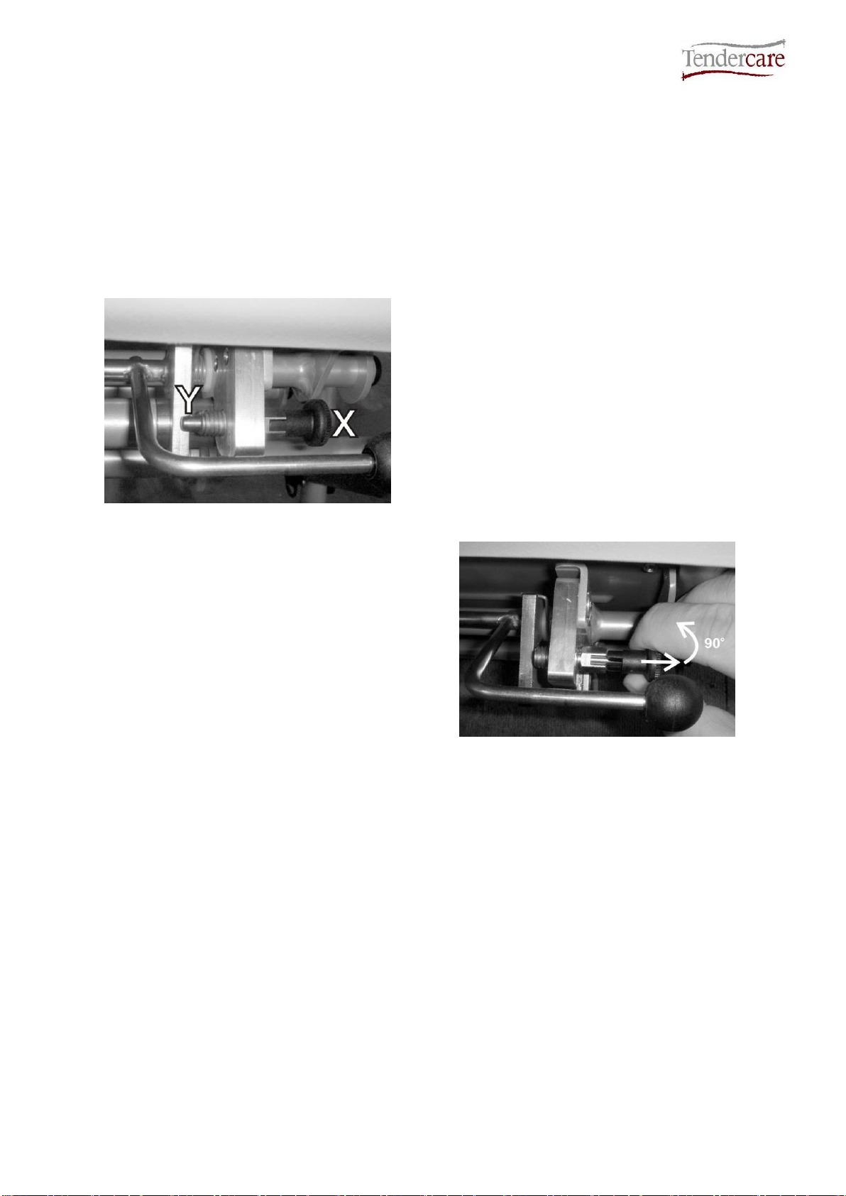
How to operate the safety catch:
Fig 4.1
Safety Catch Locked
The safety catch clip is located under the
front right corner of the seat near to the
release lever.
Definition of components:
X: Pull handle
Y: Locking Pin
To release it, pull the handle “X”, and turn it
90 degrees so that the pin “Y” is fully
retracted.
To lock it, pull “X” and turn 90 degrees in
the opposite direction, so that pin “Y” is fully
protruded and sits behind the interface main
catch “B” (see fig 4.3 on next page).
Fig 4.2
Safety Catch unlocked
Important:
When fitting or removing the seat, the carer / parent must first ensure that the safety
catch pin is set in the “unlocked” position. It will not be possible to fit or remove the
seat if the latch is “locked”, and attempting to do so may cause damage to the
chassis or the seat.
Once the seat has been fitted, the carer / parent must always lock the safety catch.
Snappi Seat Standalone User Manual
Document No: 053-07 v5 Page 9 of 54 January 2019
Snappi Seat Standalone User Manual.doc
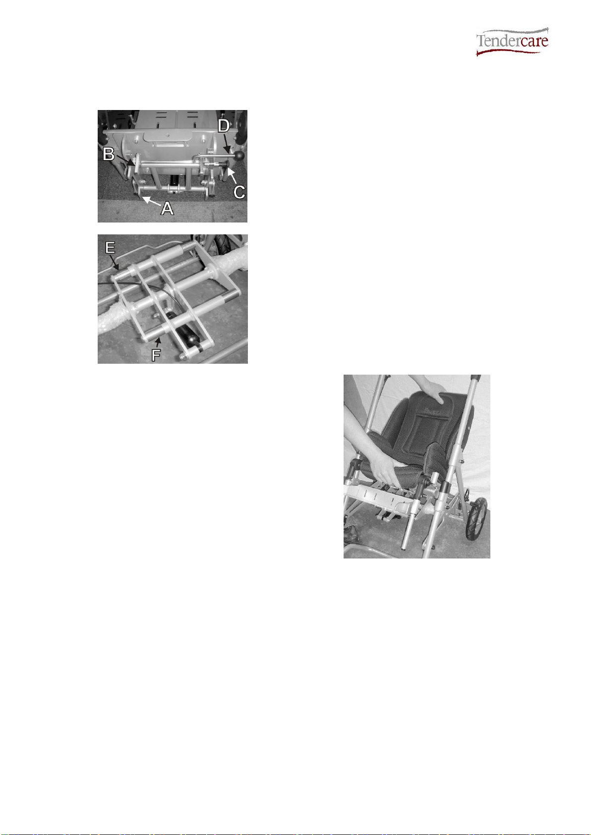
To fit the seat to the frame (note a Snappi Chassis has been used in these photos for
reference, these instructions apply to all bases the Snappi Seat can be fitted to):
Fig 4.3
Fig 4.4
Definition of interface mounting points:
A: Seat Interface Rear Hooks
B: Seat Interface Main Clips
C: Seat Interface Safety Catch
D: Seat Interface Release Handle
E: Frame interface rear bushings
F: Frame interface front bushings
Ensure that the safety catch “C” has been
unlocked (see instructions on previous
page).
Holding the seat as shown, tilt it back and
locate the 2 rear hooks “A” on the back of
the interface, over the stainless steel
bushings on the back of the frame interface
“E”.
Fig 4.5

Snappi Seat Standalone User Manual
Document No: 053-07 v5 Page 10 of 54 January 2019
Snappi Seat Standalone User Manual.doc
Fig 4.6
Next, rotate the seat forward and down so
that the main clips “B” snap over the front
stainless steel bushes on the frame
interface “F”.
Note that due to the design of the frame
interface, it is not possible to fit the seat
backwards. If fitted the wrong way around
the clips will not close and it will not sit down
into the frame.
Next, push down firmly on the release lever
“D” to ensure that the clips are fully closed.
Note the lever is positioned under the front
right corner of the seat (see Fig 4.7).
Set the safety catch “C” to the “Locked”
position (so that the pin sits behind the
interface clip).
Fig 4.7
Fig 4.8
To remove the seat, first unlock the safety
catch “C” as detailed above.
Lift the release lever “D” up, whilst holding
the top of the seat with your other hand.
This will open the main clips “B”. Rotate the
seat back so that the main clips are clear
from the frame, and lift the seat away from
the buggy.

Snappi Seat Standalone User Manual
Document No: 053-07 v5 Page 11 of 54 January 2019
Snappi Seat Standalone User Manual.doc
IMPORTANT:
❖Always ensure that the seat interface clips are fully closed. To test this, press down on the
release lever when fitted and make sure the clips will not move (see fig 4.5).
❖Always lock the safety catch before using the pushchair.
❖Always unlock the safety catch before fitting or removing the seat. Attempting to fit or
remove the seat with the catch locked could cause damage to the seat or the chassis.
❖Do not attempt to fit the seat backwards. It will not lock in a rearward facing position.
❖The seat interface system is spring loaded, so ensure your fingers are clear of the clips when
fitting or removing.

Snappi Seat Standalone User Manual
Document No: 053-07 v5 Page 12 of 54 January 2019
Snappi Seat Standalone User Manual.doc
5.0 Setting up the seat
When setting up the seat unit always ensure the following is done:
•Always consult your Therapist or Rehabilitation Engineer for advice.
•Ensure that the child is relaxed and happy and if possible in an environment in
which they are familiar.
•If possible, sit the child on a plinth to take the measurements listed below:
Fig 5.0.1 Definition of measurements
Note: you can now adjust the seat to suit your child’s dimensions
Measurement
Number
(see fig 5.0.1)
Millimetres
Top of head to seat
1
Under armpit to seat
(Axilla height)
2
Actual sitting depth
3
Chest Width
(Arm pit to arm pit)
4
Hip width
5
Leg drop
6
Snappi Seat Standalone User Manual
Document No: 053-07 v5 Page 13 of 54 January 2019
Snappi Seat Standalone User Manual.doc
5.1 Adjusting the seat unit
Common adjustments on the Snappi Seat can be made by hand (such as back height and
back recline angle) and require no tools. Less frequent adjustments are made using a
5mm hexagon key (supplied), such as the seat depth and width. No other tools are
required to make adjustments to the seat.
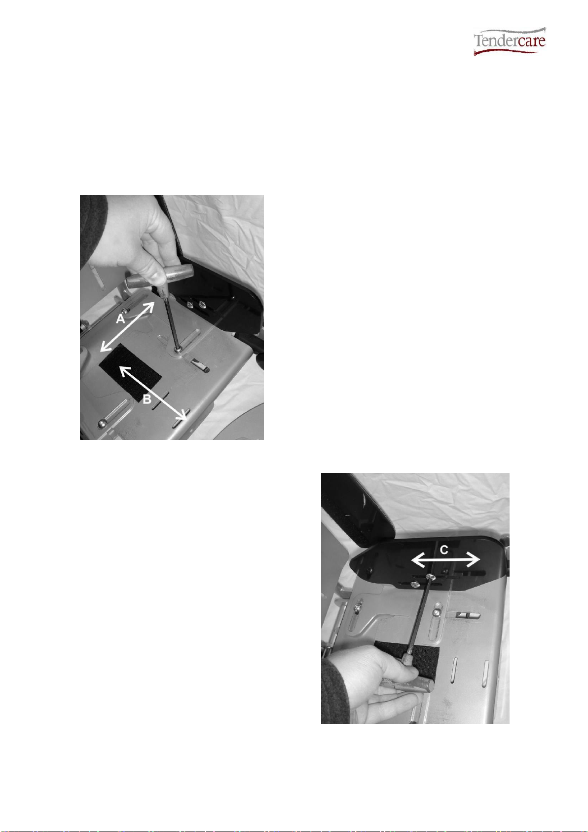
5.1.1 Seat Depth and Hip Guides
Fig 5.1.1.1
To adjust the seat depth and width, first
remove the seat base cover (this is attached
by Hook & loop in the centre of the seat and
is easily removed by pulling it away from the
frame).
Using the supplied 5mm hexagon key,
loosen the 4 seat fixings.
Next set the seat width (‘A’ see Fig 5.1.1.1)
as measured in section 5.0 by sliding the
hip guide brackets in or out as required.
To adjust the seat depth (‘B’ see Fig
5.1.1.1), slide the upper of the base plates
forward or back to achieve the required
position.
Once adjusted, tighten the 4 bolts using the
hexagon key and fit the cover back into
place.
The Snappi Seat hip guide also offers depth
adjustment (‘C’ see Fig 5.1.1.2) to best suit
your child’s needs.
To adjust this, remove the hip guide cover.
This is done by unclipping the two “poppers”
and lifting the cover off the plastic plate.
Next, use the 5mm hexagon key to loosen
the 2 fixings, and slide the plate into the
desired position as shown (see Fig 5.1.1.2).
Once adjusted, tighten the 2 fixings and refit
the hip guide cover.
Fig 5.1.1.2
Snappi Seat Standalone User Manual
Document No: 053-07 v5 Page 14 of 54 January 2019
Snappi Seat Standalone User Manual.doc
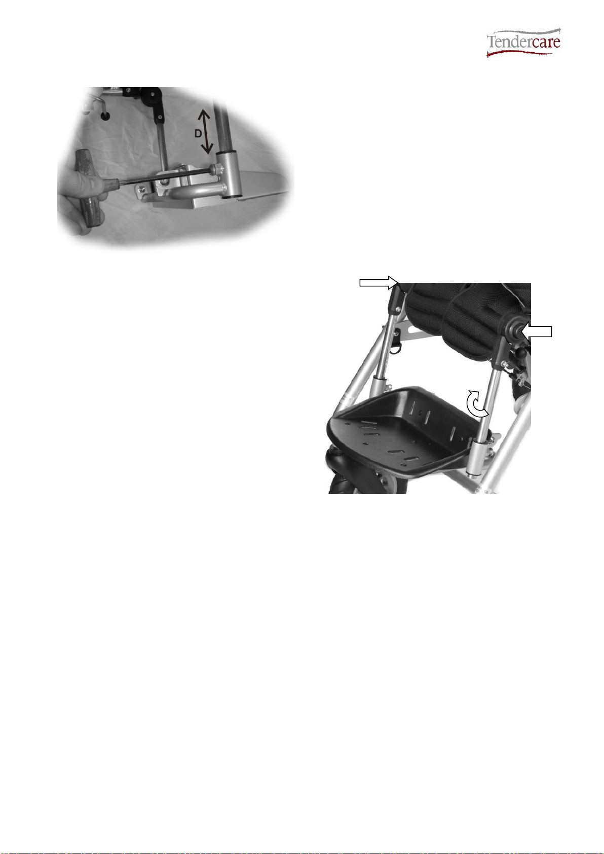
5.1.2 Footrest Depth and Knee Angle Adjustment
Fig 5.1.2.1
To adjust the foot depth, loosen the 2 securing
bolts (size 1) using the 5mm hexagon key as
shown (see Fig 5.1.2.1). On some size 2
models, wing nuts may be fitted in place of
bolts, and therefore the adjustment can be
made by hand.
Slide the footrest up or down the guide tubes
to the required height as measured in section
5.0
Once set, lock the position by tightening the 2
fixing bolts / wing nuts.
To adjust the knee angle, press in the
angle adjustors on both sides of the
footrest at the same time (see Fig 5.1.2.2),
and lift the footrest guide tubes to the
required angle. To lock, release the
buttons.
Note that the adjustors can only be locked
in 15° increments.
If the seat is paired with an old style
rearward facing Snappi it may be
necessary to reduce the length of the
footrest stems to avoid the footrest
catching and inadvertently operating the
brake bar. Alternatively the buggy can be
placed in some degree of tilt and space to
avoid this situation.
Fig 5.1.2.2
Snappi Seat Standalone User Manual
Document No: 053-07 v5 Page 15 of 54 January 2019
Snappi Seat Standalone User Manual.doc
5.1.3 Back height and recline angle adjustment
Fig 5.1.3.1
To adjust the back height, first un-tuck the
cover from the bottom of the seat (the cover
doesn’t need to be removed).
Next, turn the 2 large central hand wheels
on the back plate, as shown in Fig 5.1.3.1,
anticlockwise by either half a turn or, if
necessary, one full turn.
Once these are loose, raise or lower the
upper section of the back to the required
height, and turn the 2 hand wheels
clockwise until tight to lock it back into
place.
Once adjusted, tuck the cover back around
the bottom of the seat with the excess
sitting between the lower back plate and the
gas spring.
N.B. Before adjusting the back height you
may need to remove any lateral trunk
supports and/or the top straps of any chest
harnessing.
To adjust the back angle, grip the
adjustment lever and lift it up, whilst holding
the rear cross bar with your thumb. (See Fig
5.1.3.1)
To recline the seat, pull the top of the seat
backwards to the required angle, and
release the adjustment lever. For seats
fitted with a dynamic gas strut, the dynamic
strut restrictor will reduce the amount of
seat recline (see Fig. 5.1.3.2). If full recline
is needed, the restrictor needs to be
removed (see Snappi Pushchair Workshop
Manual about how to do this). Warning: the
restrictor must be in place if this Snappi
is to be transported.
To bring the seat back to a 90° position, pull
the release lever and gently lift the seat (the
gas spring will assist in returning the seat).
Once at the required angle, release the
adjustment lever.
Fig 5.1.3.2
Adjustment
Lever
Rear Cross
Bar
Hand
Wheels
Dynamic strut
restrictor
Snappi Seat Standalone User Manual
Document No: 053-07 v5 Page 16 of 54 January 2019
Snappi Seat Standalone User Manual.doc
5.1.4 Lateral Supports (Optional)
Fig 5.1.4.1(Lateral Trunk Supports with Chest
Belt)
Fig 5.1.4.2(Lateral Trunk Supports)
The lateral trunk supports are supplied
with two M8 coach bolts, and two 30mm
hand wheels per bracket (see Figs
5.1.4.1and 5.1.4.2).
To fit the laterals:
The laterals are fitted by securing with
coach bolts and hand wheels, through
the mounting slots ‘H’ (see Fig 5.1.4.3)
on the back of the seat unit.
Fig 5.1.4.3
Fig 5.1.4.4
The lateral bracket must be fed through the slot
in the cover (see Fig 5.1.4.4).
Next, insert the 2 coach bolts through the
bracket and seat back plate, so that the square
neck is sitting fully in the slots.
H
Snappi Seat Standalone User Manual
Document No: 053-07 v5 Page 17 of 54 January 2019
Snappi Seat Standalone User Manual.doc
Finally, secure the laterals by screwing
the provided hand wheels onto the
protruding threads of the coach bolts
(see Fig 5.1.4.5).
The position of the laterals can be
adjusted laterally by loosening the hand
wheels and sliding them in or out to the
required width.
They can be adjusted vertically by
sliding up and down the mounting slots
‘H’(see fig 5.1.4.3). There is a partition
in the slots between the upper and
lower back plates. To achieve the full
adjustment range, the laterals need to
be fitted in the appropriate section of
the slots.
Fig 5.1.4.5
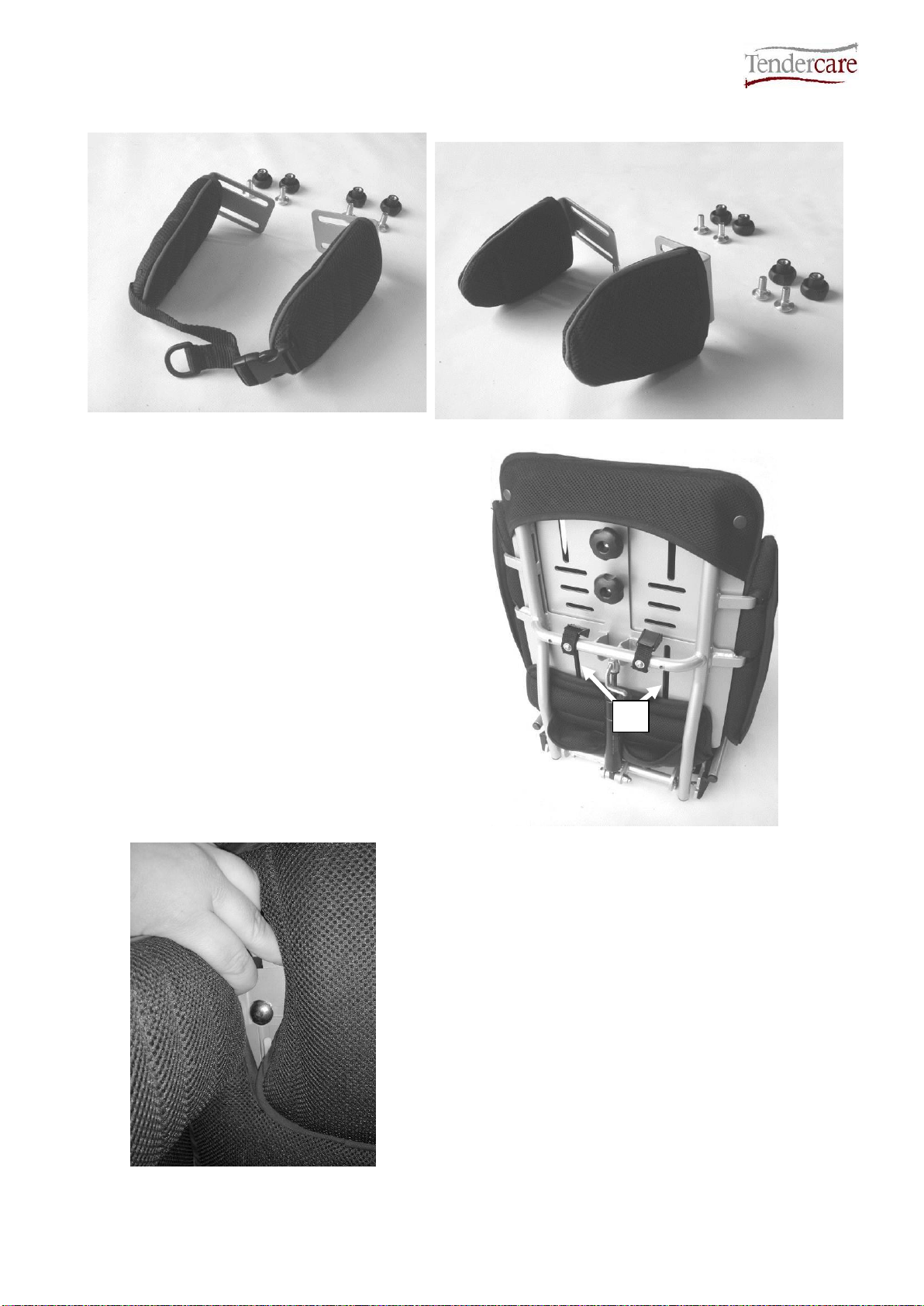
5.2 Fitting and removing the cover
Fig 5.2.1
To remove the seat pad:
Simply lift the front edge of the seat pad to
separate it from the Hook & loop strip on the
base.
To remove the hip guide covers:
The cover hooks around the front of the hip
guide plate. To remove, lift and rotate the
cover from the rear as shown, and then
unhook the cover from under the front of the
hip guide plate.
Fig 5.2.2

Snappi Seat Standalone User Manual
Document No: 053-07 v5 Page 18 of 54 January 2019
Snappi Seat Standalone User Manual.doc
Fig 5.2.3
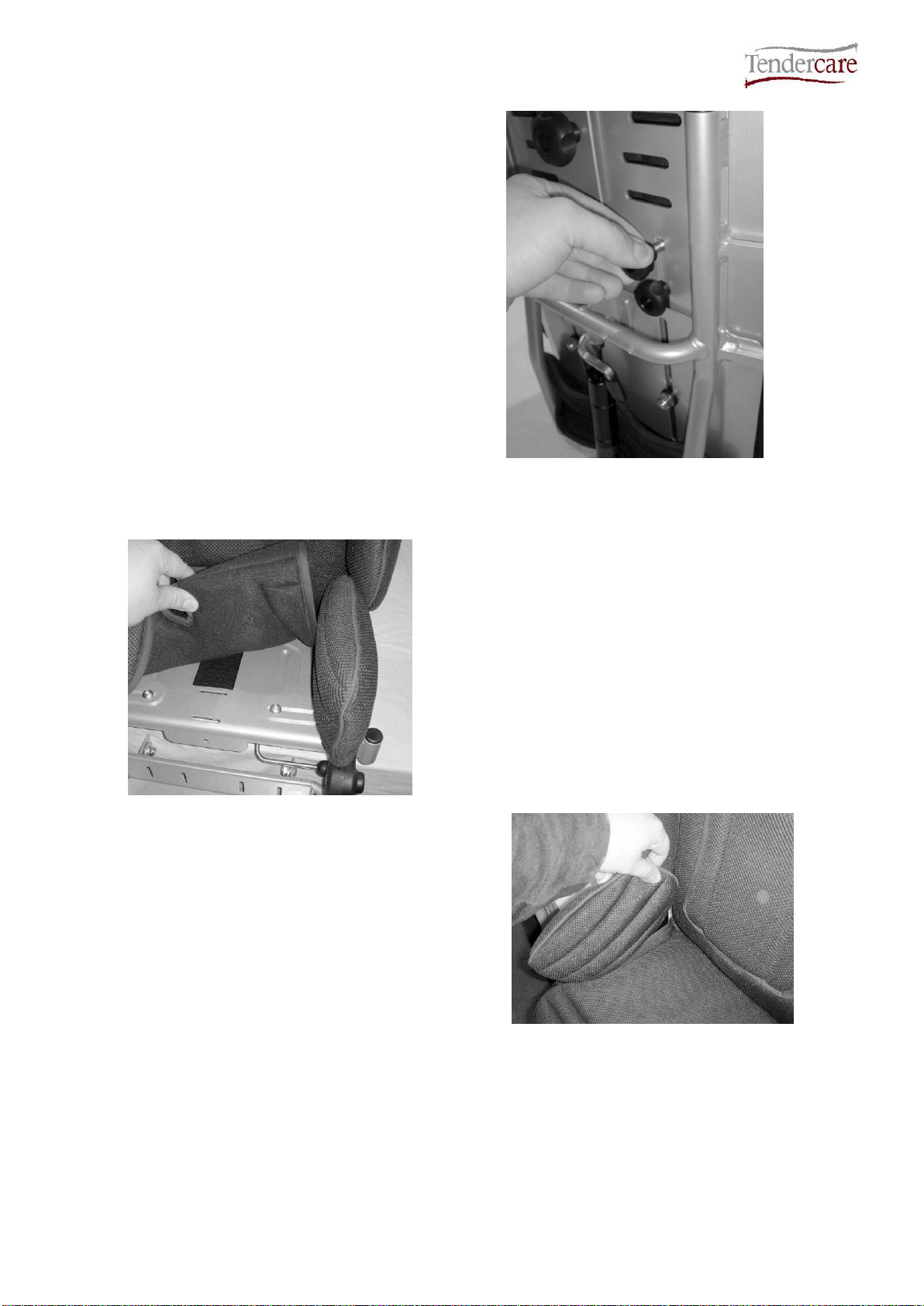
To remove the side pads:
Undo the 2 ‘popper’ fasteners, (See Fig
5.2.3) and unpeel the Hook & loop securing
the pad.
The pad will then be free to remove.
To remove the back pad:
Undo the 2 ‘popper’ fasteners located on
the top left and right corners of the seat (see
right).
Next unhook the top of the back pad from
the seat, and then un-tuck the material from
around the bottom of the seat back plates to
release the cover.
Fig 5.2.4
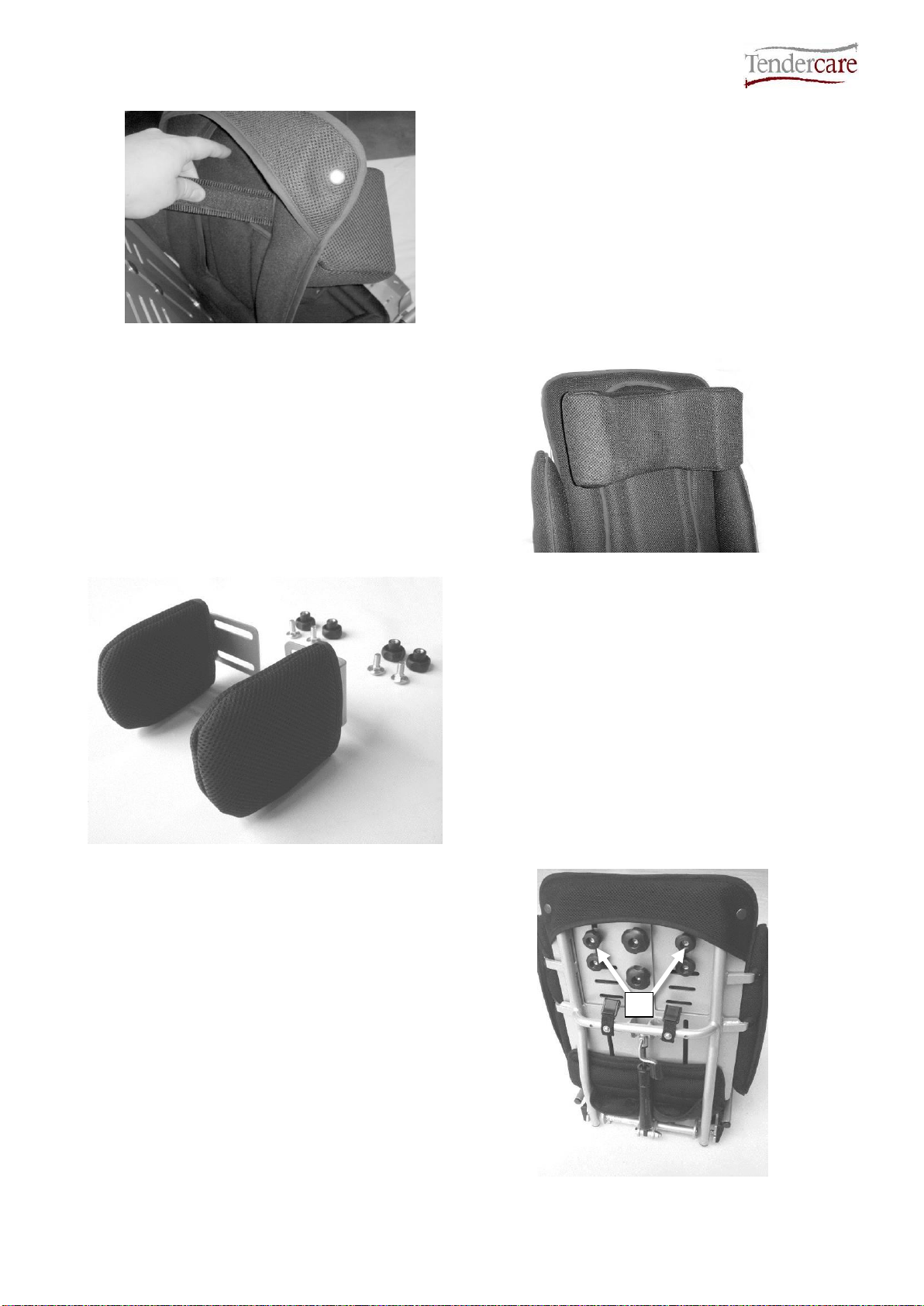
5.3 Fitting a Headrest Pad or Lateral Head Supports (optional)
Fig 5.3.1
To fit a headrest pad:
There are three types of one piece headrest
available; standard, extra recess (Fig 5.3.1)
and occipital roll, however these can all be
fitted to the seat in the same way.
The headrest pads include a pair of Hook &
loop securing straps.
The headrest is fitted to the cover, through
the upper fitting slots (see Fig 5.3.2).
Fig 5.3.2
Snappi Seat Standalone User Manual
Document No: 053-07 v5 Page 19 of 54 January 2019
Snappi Seat Standalone User Manual.doc
Fig 5.3.3
First, remove the seat back pad from the
frame (see section 5.2).
Next, feed the Hook & loop straps though
the slots, and join together to secure the
headrest in place.
Finally, refit the seat back pad to the seat
frame.
Fig 5.3.4
Fig 5.3.5
The lateral head supports are supplied with
two M8 coach bolts, and two 30mm hand
wheels per bracket (see Fig 5.3.5)
To fit the head supports:
The lateral head supports are fitted by
securing with coach bolts and hand wheels,
through the mounting slots ‘I’ (see Fig 5.3.6)
on the back of the seat unit.
The position of the laterals can be adjusted
laterally by loosening the hand wheels and
sliding them in or out to the required width.
They can be adjusted vertically by sliding up
and down the mounting slots ‘I’ (see fig
5.3.6).
Fig 5.3.6
I

Snappi Seat Standalone User Manual
Document No: 053-07 v5 Page 20 of 54 January 2019
Snappi Seat Standalone User Manual.doc
5.4 Fitting the Pelvic Strap
Unless a 4-point pelvic strap (Fig 5.4.2) is
ordered, the seat will come provided with a
2-point pelvic strap (Fig 5.4.1) fitted as
standard.
Fig 5.4.1 (Supplied as standard)
Fig 5.4.2(Optional Extra)
The pelvic strap should be fitted to the seat
such that the 2 padded areas are facing the
back of the seat (so that they will be against
the child when he / she is in the seat)
To fit the 2-point pelvic strap to the old-style
Snappi, (which can be distinguished by
having only one cam-lock buckle on each
side):
Open the cam-lock buckles (these are
located on the bottom left and right corners
of the seat base).
Feed the webbing of the strap through the
cam lock. (See Fig 5.4.3)
Fig 5.4.3
Fig 5.4.4
Adjust the length of the pelvic strap by
pulling the webbing through the cam buckle
until it is at the required length. (Fig 5.4.4)
Once adjusted, lock the cam buckle on both
sides to secure the strap.
Important: The pelvic strap must be located
as low down over the hips as possible. It
must not cross the stomach of the
passenger.
Top Straps
Table of contents
Other Tendercare Stroller manuals

Tendercare
Tendercare Snugseat Snappi User manual

Tendercare
Tendercare Snugseat Snappi User manual

Tendercare
Tendercare Snazzi Instruction manual

Tendercare
Tendercare Snappi Pushchair User manual

Tendercare
Tendercare Nursery Snugseat Spring User manual

Tendercare
Tendercare Swirl User manual

Tendercare
Tendercare Cloud Instruction manual

Tendercare
Tendercare Swirl Instruction manual

Tendercare
Tendercare Snapi Pushchair User manual

Tendercare
Tendercare Snazzi User manual


