Tenma 72-10395 User manual

Model 72-10395 Operating Manual
Pocket Size Digital Multimeter
Model: 72-10395

Model 72-10395 Operating Manual
Content
Ⅰ
.Rules for Safe Operation .......................................................................................1
Ⅱ
.Product Overview .....................................................................................................1
Ⅲ
.Functions ..............................................................................................................................2
A. ....................................................................................................................O
utline structure .............................................................................................................2
B......................................................................................................................B
utton function descriptions ............................................................................................ 2
Ⅳ
.Technical Specifications............................................................................................3
A. ....................................................................................................................G
eneral specifications ...................................................................................................3
B......................................................................................................................A
ccuracy specifications .................................................................................................4
Ⅴ
. Operations ..........................................................................................................................5
1............................................................................................................................... D
C voltage measurement..............................................................................................5
2............................................................................................................................... A
C voltage measurement ...........................................................................................5
3............................................................................................................................... R
esistance measurement .............................................................................................6
4............................................................................................................................... F
requency and duty cycle measurement ..................................................................6
5............................................................................................................................... D
iode and continuity measurement ...........................................................................6
6............................................................................................................................... C
apacitance measurement...........................................................................................7
Ⅵ
. Battery Replacement .................................................................................................... 7

Model 72-10395 Operating Manual
1
I. Rules for Safe Operation
Please pay attention to the warning symbol and its corresponding contents.
Warning items state situations or actions that may cause potential danger to users or
lead to the meter or measured equipment damage.
72-10395 digital multimeter is designed and manufactured in accordance with IEC61010,
double insulation, CAT II 600V overvoltage and pollution grade 2 safety standard.
Please operate according to this manual, otherwise the protection provided by the
device will be impaired or fail.
1. Check if the wire, probe and case insulation functionis normal or not before using. If
you find it is obviously abnormal, or you consider the device is broken, do not use
the device any more.
2. Keep your fingers behind the protection ring when using test probes
3. To avoid electric shock and meter damage, do not apply voltage higher than 600V
between the terminals and the grounding.
4. Be careful when the measured voltage is above DC 60V and AC 42V RMS so as to
avoid electric shock.
5. Do not use the meter before the back cover is well installed.
6. No measured signal should be above the specified limits.
7. No stall change of rotary knob is allowed during measurement.
8. Do not change internal wiring without authorized permission. As it will cause meter
damage and user injury.
9. To ensure accurate readings, please change batteries timely if “” icon appears on
LCD.
10. Do not apply the meter in high temperature and humidity environments; especially
do not store it in moistenvironment so as to avoid meter degrading.
11. Clean the case with soft and wet cloth and mild detergent instead of abrasive or
dissolvent for maintenance.
Safety symbols
Low Battery Indicator Grounding Warning
AC
DC
Double Insulation
Buzzer Continuity Diode Capacitance
Conformity with European Union standards
II. Product Overview
72-10395 is a pocket sized3 3/4 bit auto range digital multimeter. It has many
advantages, such as stable performance, small size, lightweight, high accuracy, low
power consumption, safe and easy to operate, and more. It is an ideal tool for

Model 72-10395 Operating Manual
2
measuring AC/DC voltage, frequency, duty cycle, resistance, capacitance, diode,
forward voltage drop and continuity.
The manual has specified the rules for safe operation and notes. Please read it
carefully before using the device and strictly follow all warnings and notes during
operation.
Warning: Please read “Rules for Safe Operation” before operation.
III.Functions
A. Outline structure (See figure 1)
1. LCD display
2. Selecting resistance, capacitance, diode or continuity measurements (SELECT
button)
3. Relative value measurement (REL button)
4. Rotary knob
5. Hz/% measurement (DCV, ACV, and Hz/% stall)
6. Data Hold
7. Positive input end (red test probe)
8. Negative input end (black test probe)
B. Button Function Descriptions
1. SELECT button
It is used for function switching among resistance, capacitance, and buzzer continuity
and diode measurements, indicated by beeping during the operation.
Press the button to activate the device in standby mode and cancel the auto power off
function
2. REL button (Relative Value Measurement)

Model 72-10395 Operating Manual
3
Press the button, then the current reading is set as reference value which will be
automatically subtracted from subsequent measurement readings. Press it again to exit
and return to normal measuring mode. This function is not available during frequency
and duty cycle measurement.
3. Data Hold (HOLD Button):
Press this button to hold displayed values; press it again to exist hold status and return to
normal measuring mode.
4. Hz/% Measurement:
Press the button to switch to Hz or % measurement under DCV and ACV ranges(the Hz/%
buttoncan be used for measuring switching between frequency and duty cycle); when
Hz/% measurement is finished, the meter will return to DCV or ACV measuring mode
with the range being 400mVand 4V respectively and meanwhile “AUTO” icon on LCD
disappears. If high voltage measurement is needed at the moment, please turn rotary
knob or turn off the meter to reset autorang for V, μA, mA measurement before starting
the test.
Under Hz/% mode, press Hz/% button to switch between Hz and % measurement.
IV.Technical Specifications
A. General specifications
1. Max voltage between the voltage input terminal and ground: 600Vrms or 600 DCV
2. Range selection: Auto
3. Measuring rate: 3 times per second
4. Max display: 3999; 3 3/4 digits
5. Over range display:“OL”
6. Polar indication: “-”icon for negative input
7. Low battery display: “ ” icon on LCD
8. Internal battery: one Lithium-manganese button cell, 3V, model: CR2032
9. Operating temperature: 0℃~40℃(32℉~104℉), humidity ≤75%
Storage temperature: -10℃~50℃(14℉~122℉)
Operating altitude height: ≤2000m
10.Dimension: 109.8mm x 58.2mm x 10.8mm
11.Weight: about 76g (including test probes and battery)
12.Auto Power Off
The meter will enter the standby mode ifno operation with the rotary switch and
buttons within about 30 minutes. In the standby mode, it can be activated (i. e. enters
the working mode) by turning the rotary switch or pressing any buttons on the front
panel. But pressing SELECT button to activate the meter will cancel Auto Power Off
function.
B. Accuracy specifications
Accuracy: ± (a% readings+ b digits), 1-year warranty period
Ambient temperature: 23℃±5℃
Relative humidity:≤75%

Model 72-10395 Operating Manual
4
Function Range Resolution
Accuracy± (a%
readings +b
digits)
Input
Protection Description
DC
Voltage
(DCV)
4V 1mV
± (0.8%+1) 600V DC
600V AC Input impedance≥10MΩ
40V 10mV
400V 100mV
600V 1V ± (1%+3)
AC
Voltage
(ACV)
4V 1mV
± (1.2%+3) 600V DC
600V AC
Input impedance≥10MΩ;
Frequency response:
40~400Hz;
Display: RMS of sine
wave(mean value response)
40V 10mV
400V 100mV
600V 1V ± (1.5%+5)
Resistance
(Ω)
400Ω
0.1Ω
± (1.2%+2)
600V AC Open circuit voltage is about
0.45V
4kΩ1Ω
± (1%+2)
40kΩ10Ω
400kΩ100Ω
4MΩ 1kΩ± (1.2%+2)
40MΩ 10kΩ± (1.5%+2)
Function Range Resolution
Accuracy±
(a% readings
+b digits)
Input
Protection Description
Capacitance
CAP (F)
4.000nF 0.001nF
600V AC
For reference only
40.00nF 0.01nF
±(4%+3)
Measuring in relative
measuring mode, the open
circuit voltage is around 0.45V
400.0nF 0.1nF
4.000μF 0.001μF
40.00μF 0.01μF
100μF 0.1μF ±(5%+10)
When measured capacitance
is above“100μF”, the reading
is for reference only
Frequency
(Hz)
99.9Hz 0.1Hz
±(0.5%+3) 600V AC
Input sine wave,
10Hz~10kHz:≥1Vrms
10kHz~100kHz:≥30Vrms
0.999kHz 0.001kHz
9.99kHz 0.01kHz
99.9kHz 0.1kHz
Duty Cycle 0.1%~99.9% 0.10% 600V AC
Press DUTY buttonto switch to the
measuring mode when the knob is
turned to AC/DC stall (the reading is
for reference only)
Diode
1mV 0.5V~0.8V 600V AC Open circuit voltage is about
1.5V

Model 72-10395 Operating Manual
5
Buzzer
Continuity
0.1Ω About≤60Ω 600V AC
Continuity resistance
≤60Ω: buzzer beeps;
>60Ω: not necessarily to
beep, and displays
approximate resistance value
with unit“Ω”
Low
Voltage
Indication
About<
2.4V icon appears
V. Operations
Check if the LCD screen displays icon to indicate the battery is low after turning on the
meter. If it does, to ensure measuring accuracy, please replace the battery. You should also
take notice of notes beside icon. They can remind you of not measuring the voltage
higher than the limit before measurement.
1. DC voltagemeasurement (See Figure 2)
(1) Turn the knob to DCV stall, AUTO and DC icons appear on LCD;
(2) Connect the black test probe to the cathode of the power to be measured and the red
test probe to the anode of the power to be measured;
(3) Read measuring results displayed on LCD;
(4) Reverse test probes in measurement, then LCD will display negative readings.
Figure 2 Figure 3
2. AC voltagemeasurement(See Figure 3)
(1) Turn the knob to ACV stall, Auto and AC icons appear on LCD;
(2) Connect the black test probe to the cathode of the power to be measured and the red
test probe to the anode of the power to be measured;
(3) Read measuring values displayed on LCD;
(4) Reverse test probes in measurement, then LCD will display negative readings.
Warnings:
Do not input voltage above 600V, you may get desired values, however, it may risk
ofdamaging the internal wiring.
To avoid electric shock, please use it with extreme caution when measuring high

Model 72-10395 Operating Manual
6
voltages.
Disconnect test probes from the measured circuit after finishingmeasurement.
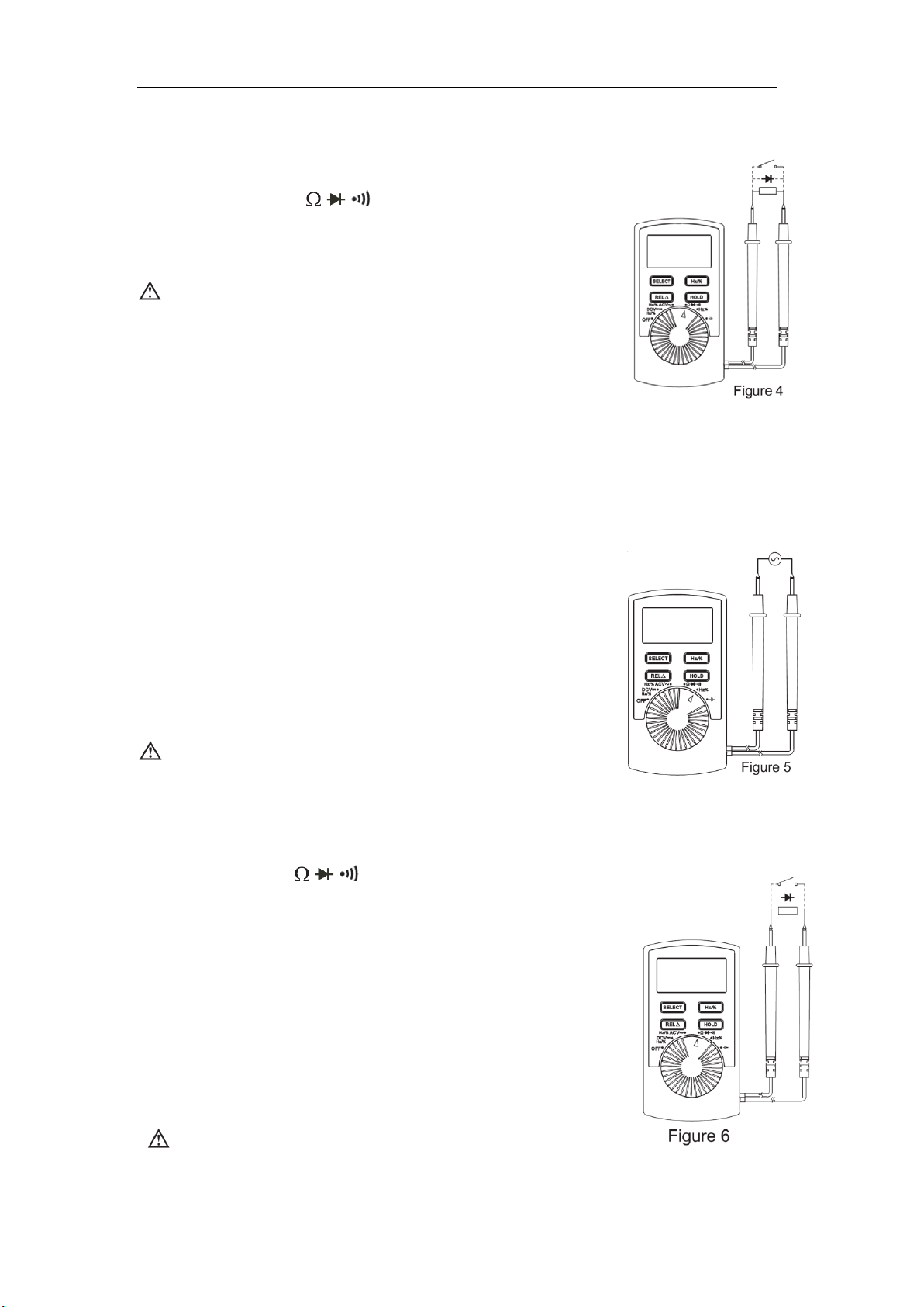
3. Resistancemeasurement (See Figure 4)
(1) Turn the knob tostall;
(2) Connect test probes in parallel to the resistance to be
measured;
(3) Read measured results on the display.
Notes:
To avoid meter damage, when measuring the
resistance in line, please make sure the measured
circuit power is turned off; meanwhile all capacitance
has been discharged before measurement.
As for 400Ω resistance measurement, test probes will cause 0.1Ω~0.3Ω measuring
deviation. In order to get accurate readings, the ultimate results should subtract the
short circuit reading values of the red and black test probes. It is suggested to
performthe operation in relative value measurement mode.
The meter displays“OL” when no signal is input, for instance, in open circuit condition.
For measurement≥1MΩ, it normally takes several seconds to get stable readings.
4. Frequency and duty cyclemeasurement(See Figure 5)
(1) Turn the knob to Hz/%, DCV or ACV stall;
(2) Press Hz/% button to access frequency measurement;
(3) Connect test probes in parallel to frequency signal
source to be measured;
(4) Read measured results on the display;
(5) Press Hz/% button again to access % measurement.
Notes:
The measured resolution based on frequency and
waveform will vary slightly. The meter resolution has
been set according to sine wave.
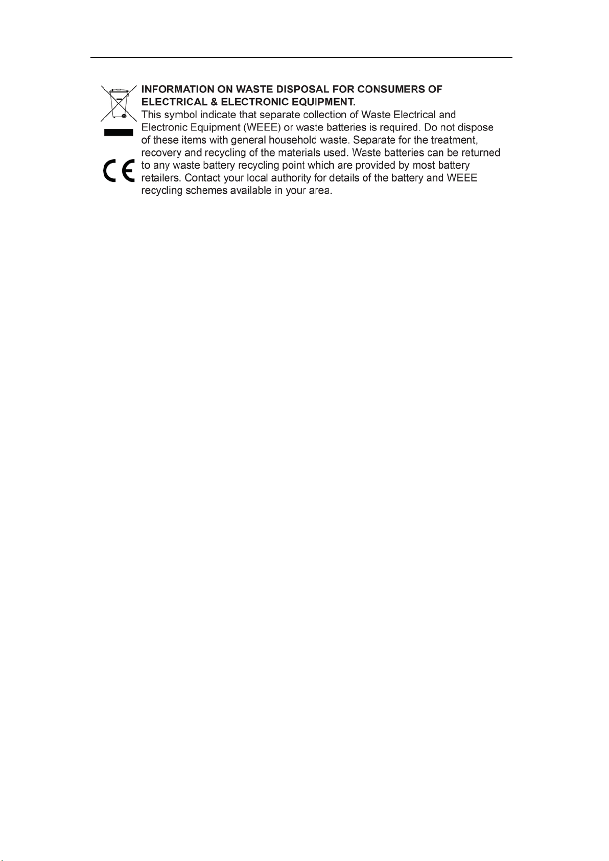
5. Diode and continuitymeasurement(See dotted part in Figure 6)
(1) Turn the knob to stall;
(2) Press SELECT button to access diode mode(press it
again to switch to continuity test);
(3) If connect test probes to the diode to be
measured(with black test probe to cathode and red
test probe to anode), then the reading on LCD will be
an approximate value of diode forward voltage
drop(when connecting test probes to both ends of the
circuit to be measured, if the resistance between these
two ends is≤60Ω, the built-in buzzer will go off and the
resistance value appears on LCD).
Notes:
If the measured diode is under open circuit status or the

Model 72-10395 Operating Manual
7
polarity is wrongly connected (namely, with black test
probe connecting to anode and red test probe to cathode),
LCD will display“OL”.
Turn the knob to this diode stall, the meter can measure the voltage drop of PN joint of
diode and other semiconductors. For a silicon semiconductor with normal structure, the
reading of the forward voltage drop should be within 0.5~0.8V.
To avoid meter damage, before measuring the resistance in line, please make sure the
measured circuit power is turned off, and all capacitance has been discharged.
In order to avoid meter damage or injuries, do not inputvoltage above 60V DC or 30Vrms
AC.
6. Capacitancemeasurement (See Figure 7)
(1) Turn the knob to stall;
(2) As there is a capacitance reading displayed under open-circuit status, please select
relative value measuring mode;
(3) Press REL button once;
(4) Connect test probes to the capacitance to be measured,
and read data on LCD.
Notes:
Fully discharge capacitance before measurement.
As for in-line capacitance measurement, it is required
to turnoff all power supplies in the measured circuit
and fully discharge all capacitors.
If the capacitance being measured has polarity, ensure
that the red probe is connected to the anode of
capacitance and the black one to the cathode of
capacitance during measurement.
It normally takes several seconds to display the testing value when measuring
capacitance higher than 10uF.
To avoid meter damage or injuries, do not input voltage above 60V DC or 30Vrms AC.
VI.Battery Replacement
If icon appears on LCD, please replace the battery as follows:
1. Disconnect test probes from circuits being measured, turnrotary knob to OFF position,
then turn off the meter.
2. Unscrew the back casewith a screwdriver and remove the case.
3. Replace the 3V battery with a new one.

Model 72-10395 Operating Manual
8
Tenma Test Equipment
405 S. Pioneer Blvd.
Springboro, Oh
www.tenma.com
Other manuals for 72-10395
1
Table of contents
Other Tenma Multimeter manuals

Tenma
Tenma 72-8720 User manual

Tenma
Tenma 72-2590 User manual

Tenma
Tenma 72-10395 User manual

Tenma
Tenma 72-1015 User manual

Tenma
Tenma 72-10405 User manual

Tenma
Tenma 72-10390A User manual

Tenma
Tenma TEN01061 User manual

Tenma
Tenma 72-7720 User manual

Tenma
Tenma 72-8495 User manual

Tenma
Tenma 72-1055 User manual

Tenma
Tenma 72-8155 User manual

Tenma
Tenma 72-10465 User manual

Tenma
Tenma 72-8715 User manual

Tenma
Tenma 72-7730A User manual

Tenma
Tenma 72-3097 User manual

Tenma
Tenma 72-7780 User manual

Tenma
Tenma 72-9380A User manual

Tenma
Tenma 72-2600 User manual

Tenma
Tenma 72-13430 User manual

Tenma
Tenma 72-7765A User manual