recovery fuse, F3 (0.5A H 250V) Fast blow
250V) Fast blow fuse Φ5x20mm
250V) Fast blow fuse Φ5x20mm Press Hold to enter and exit the hold mode
Display backlight power
ADC Current Measurement
Unit of electrical capacity: Accepts farad,
microfarad
Unit of Voltage: millivolt, volt
10. Number Test reading
Continuity Alarm
Diode Test
Data Hold
Negative Reading
High voltage
Manual Range Indicator
Warning Indicator
Low Battery
20. Product size: 300 x 245 x 105 mm
18. Electromagnetic Field: Under 1V/m from inuence
electric shock and even personal injury.
COM: 1000V (except 200mV, 230V)
11. Turn the meter off when it is not is use. Take out
indicator “ ”appears. With a low battery, the
meter, and possibly cause injury or death.
for any reason. Doing so will cause damage to the
9. Do not alter the internal circuit of the meter
the meter may deteriorate after this type of use.
ature, high humidity, flammable, or highly
8. Do not use or store the meter in a high temper-
measurement function.
range position, do not change the range during the
7. Once the rotary switch is placed in the correct
which the meter will indicate the overload.
terminals or between the terminals and a ground;;;;;;,
6. Do not overload voltage or current between the
value and adjust down until you get a a reading.
are not sure of the current range, simply start with a high
rotary switch to select the measuring function. If you
5. Select the correct terminal input and turn the
be taken for added danger of electric shock.
4. When the meter is being used with voltages over
other circuit being tested with your bare skin or hands.
3. Do not touch any cable, connector, terminal or
model number or identical electrical specification
2. If test leads are damaged, use only the same
equipment being tested.
or cause further damage to the meter and any attached
to the case or insulation could cause electric shock
use the meter with the housing removed;;;;;;;;;;;. Damage
use. Do not use the Meter and Test Leads
1. Inspect both the Meter and the Test Leads before
injury.
meter to reduce the chance of damage or possible
follow these operating instructions while using the
category (CAT II 1000V) and double insulation. Please
IEC61010-1 for pollution degree 2, overvoltage
1 piece
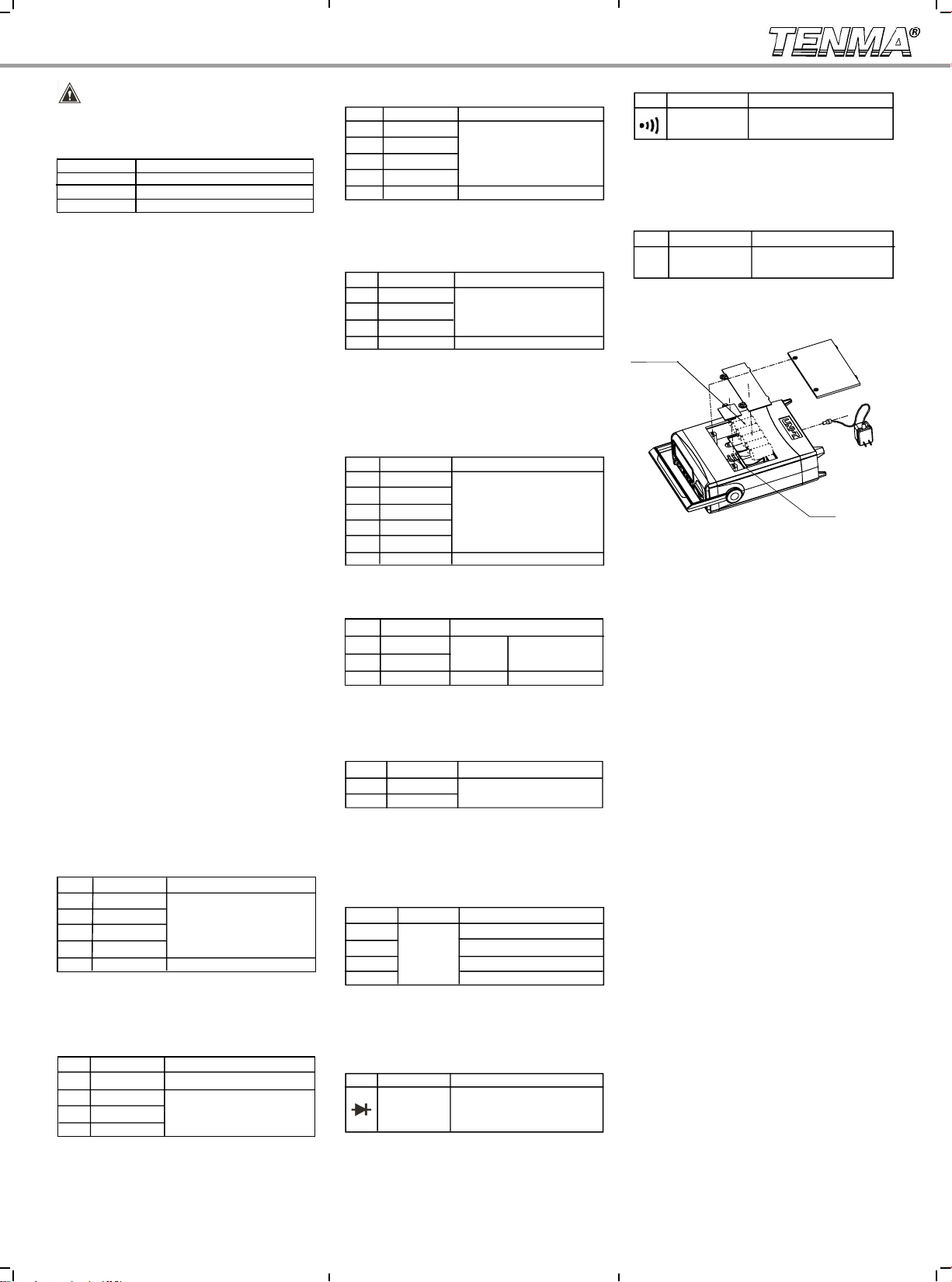
● Power Cord 1 piece
● Multi-Purpose Socket
● K Type Temperature Probe 1 piece
● Operating Manual 1 piece
● Test Lead 1 pair
● Alligator Clip 1 pair
( Maximum 230 Celcius)
parts please contact your Tenma dealer.
or damaged parts. If you nd any missing or damaged
Check the following items to see if there are missing
Open the box and carefully remove the meter.
strictlywhile using this product.
information carefully and observe all the warnings
safety and precautions. Please read all of the
This easy-to-use instrument provides the user full
This model features a 2000 count, 3-1/2 digit, extra-
ature, transistor hFE, diode, and continuity
buzzer.
current, resistance, frequency, capacitance, temper-
Measurements include DC/AC voltage, DC/AC
in a sleek and simple casing that will fit on any bench.
measurement and full overload protection, packaged
large, backlit LCD display.
Digital Bench-Type Multimeter Model 72-1055 is
a manual ranging, DC / AC current digital multimeter.
Bench Type Digital Multimeter
72-1055 Operating Manual
72-1055
LCD Display
1. Manual Range
2. Warning !
3.
4.
5.
6. AC Indicator for AC voltage or current
( DC indicator do not display)
7.
8.
9.
11. Units of measurement:
General Specications
1. Maximum Voltage between terminal input and
2. μA mA terminal input protection: (CE)250mA 265V
auto recovery fuse
3. 10A terminal input protection: (CE)F1 (10A H
4. Resistance input protection: PTC/250V
5. Capacitance input protection: (CE)F2, F3 (0.5A H
6. Frequency input protection: PTC/250V
7. Temperature input protection: (CE)250mA 265V
fuse
8. terminal input protection: PTC/250V
9. hFE input protection: (CE)250mA 265V auto
fuse Φ5x20mm
10. Display: LCD full f unction signal display,
11. Range: Manual
12. Polarity Display: Auto
13. Overload indication: 1
14. Battery Deciency:
15. Operating Temperature: 0~40℃(32℉~104℉)
16. Storing Temperature: -10~50℃(14℉~122℉)
17. Relative Humidity: 0℃~30℃ below ≤75%
30℃~40℃ ≤50%
of radiated radio-frequency electromagnetic field
measurement 5%, Over 1V/m radiated radio-
frequency electromagnetic which do not have any
reference data on this topic.
6 pieces)
accessories)
22. Safety Compaliances : IEC 61010: CATⅡ1000V
electromagnetic environment. The performance of
10. Replace the battery as soon as the battery
meter might produce false readings that can lead to
Operating Manual
Overview
This operating manual covers information on
Unpacking Inspection
(AC220V 50Hz DC9V/200mA)
Safety Information
This M eter co mplie s with th e stand a rds
replacement parts. Unit of current: Microampere, milliampere,
ampere
Unit of electrical resistance: Ohm, thousand
Unit of Frequency: Kilohertz
Unit of Temperature: Degree Celsius Factor
Unit of Triode enlargement: Times
mV, V
μA, mA, A
Ω, kΩ, MΩ
nF/μF
kHz
℃
β
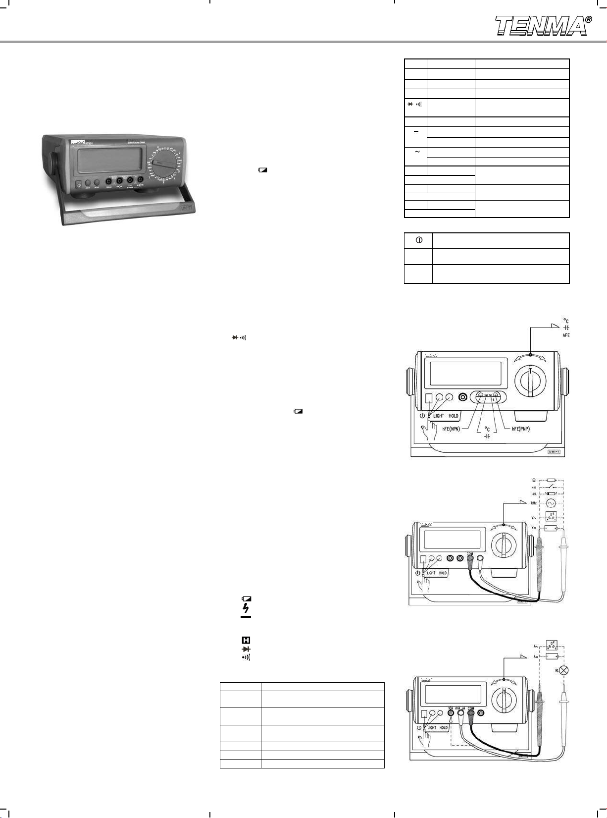
Operational Measurement Guide (see Diagram 1, 2,
3)
Diagram 1
Diagram 2
Diagram 3
Functions
Symbol Terminal Input Explanation
V V ←→ COM DC Voltage Measurement
V V ←→ COM AC Voltage Measurement
Ω V ←→ COM Resistance Measurement
V ←→ COM Diode / Continuity Buzzer
Measurement
kHz V ←→ COM Frequency Measurement
A mA μA ←→ COM mA/μA DC Current Measurement
10A ←→ COM
A mA μA ←→ COM mA/μA AC Current Measurement
10A ←→ COM A AC Current Measurement
F V←→ mA μA Capacitance Measurement
(Use Multi-Purpose Socket)
V ←→ mA μA Temperature Measurement
(Use Multi-Purpose Socket)
hFE V ←→mA μA Triode Enlargement Factor
(Use Multi-Purpose Socket) Measurement
℃
Functional Buttons
LIGHT
HOLD
thebatteries when not used for extended period of time.
Power Toggle Button
maximum reading is 1999, and updates 2-3 times /sec
effect, Total accuracy= specific accuracy+
19. Power: AC (external power adapter AC110V/
DC9V-200mA) or DC (internal battery type 2 R14/1.5V
21. Product Net Weight : About 3.3 lbs (without
ohms, trillion ohms
removed or the display is blank while in use. Do not
if either is damaged, if the protective housing is
60V DC or 30V rms AC RMS, additional care should