Tenma 72-7765 User manual

Accuracy Specifications(4)
33
Range Resolution
400µA
4000µA
40mA
400mA
4A
10A
Accuracy Overload Protection
(1.5%+5) 500mA/250V fast type
fuse φ 5x20mm
0.1µA
1µA
10µA
100µA
1mA
10mA
(2%+5)
(2.5%+5)
D. AC Current
Un-Fused
Remark:
lAt 10A Range: For continuous measurement 10 seconds and interval not less
than 15 minutes.
lInput impedance: approx. 10MΩ.
l Measurement voltage drop: Full range at 400mV.
Model 72-7765: OPERATING MANUAL

Accuracy Specifications(5)
34
E. Resistance
Range Resolution
400Ω
4kΩ
40kΩ
400kΩ
4MΩ
40MΩ
Accuracy Overload Protection
(1.2%+2)
0.1Ω
1Ω
10Ω
100Ω
1kΩ
10kΩ(1.5%+2)
(1.2%+2)
(1%+2) 250V DC or AC
Model 72-7765: OPERATING MANUAL

Accuracy Specifications(6)
Range Resolution Remark Overload Protection
Range Remark Testing Condition
35
G. Transistor hFE Test
Ibo 10µΑ
Vce 1.5V
hFE
250V DC or AC
F. Diodes and Continuity Measurement
Displays approximate forward
voltage drop
Buzzer beeps at <100Ω
1mV
0.1Ω
Test NPN and PNP type transistors.
Display range: 0-1000β
Model 72-7765: OPERATING MANUAL

36
Maintenance(1)
This section provides basic maintenance information including battery and fuse
replacement instructions.
Warning
Do not attempt to repair or service your Meter unless you are qualified to do
so and have the relevant calibration, performance test, and service information.
To avoid electrical shock or damage to the Meter, do not get water inside the
case.
A. General Service
l Periodically wipe the case with a damp cloth and mild detergent. Do not use
abrasives or solvents.
l To clean the terminals with cotton bar with detergent, as dirt or moisture in the
terminals can affect readings.
l Turn the Meter to OFF position when it is not in use and take out the battery
when not using for a long time.
l Do not store the Meter in a place of humidity, high temperature, explosive,
inflammable and strong magnetic field.
Model 72-7765: OPERATING MANUAL

37
Maintenance(3)
B. Replacing the Battery (see figure 8)
Warning
To avoid false readings, which could lead to
possible electric shock or personal injury,
replace the battery as soon as the battery
indicator “ ”appears.
To replace the battery:
1. Disconnect the connection between the test
leads and the circuit under test, and remove
the test leads from the input terminals of the
Meter.
2. Turn the Meter to OFF position.
3. Remove the screw from case bottom, and
separate the case bottom from the case top.
(figure 8)
SCREW
Model 72-7765: OPERATING MANUAL

38
C. Replacing the Fuses (see figure 8)
Warning
To avoid electrical shock,arc blast, personal injury or damage to the Meter,
use specified fuses ONLY in accordance with the following procedure.
To replace the Meter’s fuse:
1. Disconnect the connection between the test leads and the circuit under test,
and remove the test leads from the input terminals of the Meter.
2. Turn the Meter to OFF position.
3. Remove the screws from case bottom, and separate the case bottom from the
case top.
Maintenance(4)
4. Remove the battery from the battery compartment.
5. Replace the battery with a new 1.5V AAA battery.
6. Rejoin the case bottom and case top, and reinstall
the screw.
Model 72-7765: OPERATING MANUAL

** END **
39
4. Remove the fuse by gently prying one end loose, and then take out the fuse
from its bracket.
6. Rejoin the case bottom and case top, and reinstall the screw.
Replacement of the fuses is seldom required. Burning of a fuse always results from
improper operation.
5. Install ONLY replacement fuses with the identical type and specification as
follows and make sure the fuse is fixed firmly in the bracket.
Fuse 1:500mA 250 V, fast type, 5x20mm.
Maintenance(5)
Model 72-7765: OPERATING MANUAL

40
Model 72-7765: OPERATING MANUAL
Tenma Test Equipment
405 S. Pioneer Blvd.
Springboro,Ohio 45066
www.tenma.com

C. DC Current Measurement (see figure 4)
Warning
Never attempt an in-circuit current measurement
where the voltage between terminals and ground
is greater than 60V . If the fuse burns out during
measurement, the Meter may be damaged or the
operator may be injured. Use proper terminals,
function, and range for the measurement. When
the test leads are connected to the current
terminals, do not parallel them across any circuit.
Measurement Operation (4)
(figure 4)
To measure current, do the following:
1. Turn off power to the circuit. Discharge all high-
voltage capacitors.
black red
17
Model 72-7765: OPERATING MANUAL

Measurement Operation (5)
2. Insert the red test lead into the VΩmA or 10A terminal and the black test lead
into the COM terminal.
3. Set the rotary switch to an appropriate measurement position in A range. DC
measurement is default or press SELECT button to select DC measurement mode.
4. Break the current path to be tested. Connect the red test lead to the more positive
side of the break and the black test lead to the more negative side of the break.
5. Turn on power to the circuit. The measured value shows on the display.
Note
l If the value of current to be measured is unknown, use the maximum measurement
position (10A) and reduce the range step by step until a satisfactory reading is
obtained.
l When current measurement has been completed, disconnect the connection
between the testing leads and the circuit under test.
18
Model 72-7765: OPERATING MANUAL

Measurement Operation (6)
19
D. AC Current Measurement (see figure 4)
Warning
Never attempt an in-circuit current measurement where the open-circuit voltage
between the circuit and ground is greater than 500V.
If the fuse burns out during measurement, the Meter may be damaged or the
operator may be injured. Use proper terminals function, and range for the
measurement. When the test leads are connected to the current terminals,
do not parallel them across any circuit.
1. Turn off power to the circuit. Discharge all high-voltage capacitors.
2. Turn the rotary switch to suitable range, press SELECT to change from DC to AC
measurement.
3. Insert the red test lead into the VΩmA or 10A terminal and the black test lead
into the COM terminal.
4. Set the rotary switch to an appropriate measurement position in A range.
Model 72-7765: OPERATING MANUAL

Measurement Operation (7)
20
5. Break the current path to be tested. Connect the red test lead to the more positive
side of the break and the black test lead to the more negative side of the break.
6. Turn on power to the circuit.
The measured value shows on the display.
Model 72-7765: OPERATING MANUAL

Measurement Operation (8)
(figure 5)
black red
21
E. Resistance Measurement (see figure 5)
Warning
To avoid damage to the Meter or to the devices
under test, disconnect circuit power and discharge
all the high-voltage capacitors before measuring
resistance.
The Ω ranges are : 400.0Ω, 4.000kΩ, 40.00kΩ,
400.0kΩ, 4.000MΩ, and 40.00MΩ,
1. Insert the red test lead into the VΩmA terminal and
the black test lead into the COM terminal.
2. Set the rotary switch to the Ω range.
3. Connect the test leads across with the object being
measured. The measured value shows on the display.
Model 72-7765: OPERATING MANUAL

Measurement Operation (9)
22
Note
lThe test leads can add 0.1Ω to 0.3Ω of error to resistance measurement. To
obtain precision readings in low-resistance measurement, that is the range of
200Ω, short-circuit the input terminals beforehand and record the reading
obtained (called this reading as X). (X) Is the additional resistance from the test
lead. Then use the equation: measured resistance value (Y) - (X) = precision
readings of resistance.
lFor high-resistance measurement (>1MΩ), it normally requires several seconds
to obtain a stable reading.
lWhen resistance measurement has been completed, disconnect the connection
between the testing leads and the circuit under test.
Model 72-7765: OPERATING MANUAL

Measurement Operation (10)
(figure 6)
23
F. Diode and Continuity Test (see figure 6)
Testing Diodes
Warning
To avoid damage to the Meter or to the
devices under test, disconnect circuit power
and discharge all the high-voltage capacitors
before diodes.
Use the diode test to check diodes, transistors,
and other semiconductor devices. The diode test
sends a current through the semiconductor junction,
and then measures the voltage drop across the junction.
A good silicon junction drops between 0.5V and 0.8V.
black red
Model 72-7765: OPERATING MANUAL

Measurement Operation (11)
24
To test a diode out of a circuit, connect the Meter as follows:
1. Insert the red test lead into the VΩmA terminal and the black test lead into the
COM terminal.
2. Set the rotary switch to Diode measurement is default or press SELECT
button to select diode measurement mode.
3. For forward voltage drop readings on any semiconductor component, place the
red test lead on the component’s anode and place the black test lead on the
component’s cathode.
The measured value shows on the display.
Note
lIn a circuit, a good diode should still produce a forward voltage drop reading of
0.5V to 0.8V; however, the reverse voltage drop reading can vary depending on
the resistance of other pathways between the probe tips.
l Connect the test leads to the proper terminals as said above to avoid error display.
The LCD will display “OL” indicating open-circuit for wrong connection. The unit
of diode is Volt (V), displaying the positive-connection voltage-drop value.
Model 72-7765: OPERATING MANUAL

Measurement Operation (12)
25
l When diode testing has been completed, disconnect the connection between the
testing leads and the circuit under test.
Testing for Continuity
To test for continuity, connect the Meter as below:
1. Insert the red test lead into the VΩ mA terminal and the black test lead into the
COM terminal.
2. Set the rotary switch to .
3. Press SELECT button to select continuity measurement mode.
4. Connect the test leads across with the object being measured.
The buzzer sounds if the resistance of a circuit under test is less than 100Ω.
Model 72-7765: OPERATING MANUAL

Measurement Operation (13)
(figure 7)
26
G. Transistor hFE Measurement (see figure 7)
Warning
To avoid damages to the Meter or to the devices
under test, do not input any current over 60V DC
or 30V AC.
1. Check that the transistor is PNP or NPN type.
2. Connect the transistor to be measured to the
corresponding jacks.
3. LCD display hFE reference value.
Model 72-7765: OPERATING MANUAL

27
To preserve battery life, the Meter automatically turns off after 30minutes of inacjivity.
The Meter can be activated by pressing the SELECT button or turning the rotary
switch.
Sleep Mode
Model 72-7765: OPERATING MANUAL

28
lMaximum Voltage between any Terminals and Ground: 500V rms.
lFused Protection for VΩmAInput Terminal: 500mA, 250V fast type, φ5x20 mm
l10A Terminal: Un-fused.
lRange: Auto ranging
lMaximum Display: Display: 3999.
lMeasurement Speed: Updates 3 times / second.
lTemperature:
Operating: 0oC~40oC (32oF~104 oF).
Storage: -10oC~50oC (14oF~122oF).
lRelative Humidity: 75% @ 0oC - 30oC; 50% @ 31 - 40oC.
lAltitude: Operating: 2000 m.
Storage: 10000 m.
General Specifications(1)
Model 72-7765: OPERATING MANUAL
Table of contents
Other Tenma Multimeter manuals

Tenma
Tenma 72-7224 User manual

Tenma
Tenma 72-8495 User manual

Tenma
Tenma 72-9375 User manual

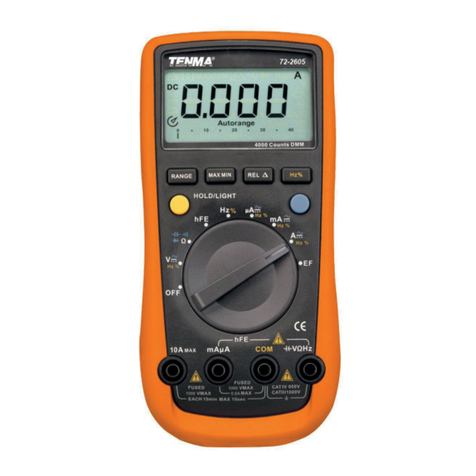
Tenma
Tenma 72-2600 User manual

Tenma
Tenma 72-8150 User manual

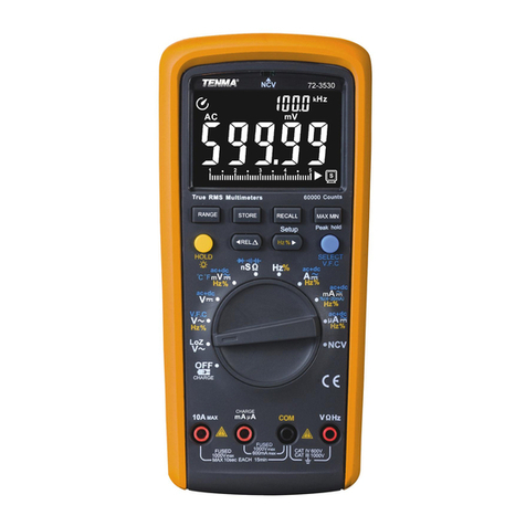
Tenma
Tenma 72-3530 User manual

Tenma
Tenma 72-9380A User manual

Tenma
Tenma 72-10395 User manual

Tenma
Tenma 72-7780 User manual

Tenma
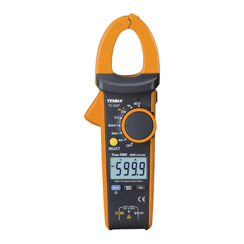
Tenma 72-3097 User manual

Tenma
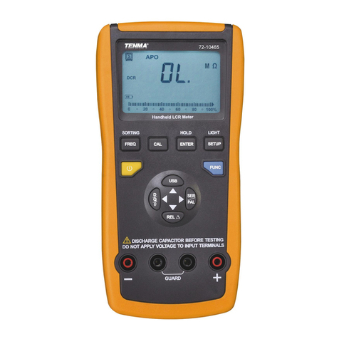
Tenma 72-10465 User manual

Tenma
Tenma UT202 User manual
Tenma
Tenma 72-2590 User manual

Tenma
Tenma 72-13430 User manual

Tenma
Tenma 72-9280 User manual
Tenma
Tenma 72-7780 User manual

Tenma
Tenma 72-10405 User manual
Tenma
Tenma 72-8715 User manual

Tenma
Tenma 72-7228 User manual

Tenma
Tenma 72-3540 User manual