Tenma 72-8495 User manual

1
Model: 72-8495
2 in 1 LAN Tester and Multimeter

2
Please read these instructions carefully before use and retain for future reference.
This instrument is designed and manufactured in compliance with: G84793,
lEC61010-1, CAT III 600V Pollution Degree 2 and Double Insulation standards.
• CAT III: Measurement category III is for measurements performed in the building
installation. Examples are measurements on distribution boards, circuit-breakers,
and wiring, such as cables, bus-bars, junction boxes, switches and socket-outlets
in the xed installation, and equipment for industrial application and some other
equipment such as stationary motors with permanent connection to the xed
installation.
• Check the test leads, probes and case insulation before using. If you nd any
breakage or abnormality, or you consider the device is broken, stop using the
device immediately.
• Only use test leads and probes that are in compliance with IEC 61010-031, and
rated CAT III 600V.
• When using the test probes, keep your ngers behind the nger protection ring.
• Do not use the meter with the battery or back cover open.
• Select appropriate test range for measurements.
• Ensure all inputs are less than the range selected otherwise it may cause electrical
shock or meter damage.
• Do not change the range selector position during voltage or current
measurements.
• Take caution when working voltages are above 35V DC or 25V AC rms.
• Do not connect the meter to voltage signals when the range selector is on current,
resistance, diode or continuity range.
• Always discharge capacitors and remove power from the device under test before
performing Diode, Resistance or Continuity tests.
• When measuring current, each single measurement should be shorter than 10
seconds. For current values over 5A, the wait period between each measurement
must be longer than 15 minutes.
• When a measurement has been completed, disconnect the testing probes from
the circuit under test.
• Replace the batteries as soon as the low battery indicator appears on the display.
• Remove dead batteries from the meter or if it is not going to be used for a long
time.
• Never mix old and new batteries together, or different types of batteries.
• Never dispose of batteries in a re, or attempt to recharge ordinary batteries.
• Before replacing the battery, turn off the meter and disconnect all the test probes.
• To prolong battery life turn off the meter after use.
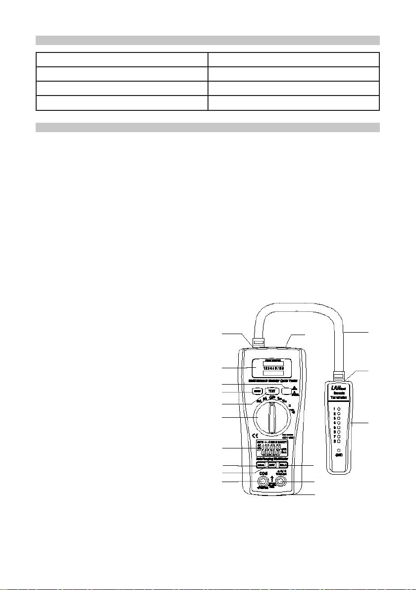
WHAT’S INCLUDED
• Digital multimeter.
• LAN tester and connection cable.
• User manual.
• Set of test leads.
• BNC cable adaptors
• 9V battery and 2 x AA batteries (installed).
• Carry case.
IMPORTANT SAFETY INFORMATION

3
FUNCTIONS
INPUT LIMITS
• 2 in 1 LAN Tester & Multimeter is a innovative tester that allows the user to
measure DC/AC voltage/current, resistance, continuity, diode and verify the cable
continuity, open short or cross-connect. The included remote terminator allows
testing of installed cable either at a wall jack or a patch panel.
• 3-1/2 digit (2000 count) LCD display for multimeter functions.
• LED Displays the actual pin conguration of 10BASE-T AND 10BASE-2 Thin
Ethernet, FJ45/RJ11 modular, 258A, tia-568a/568b and Token Ring cables.
• Double moulded housing.
• Provides easy to read continuity and fault status display.
• Auto or manual scanning for LAN tester.
Function Maximum Input
V DC or V AC 600V AC/DC
µA AC/DC 200mA/250V fast acting fuse
Resistance, Diode & Continuity test 600V AC/DC
453
2
1
6
7
8
9
10
11
12
13
15
17
16
14
1. Remote terminator with LED display
for receiving end
2. Jack RJ45
3. LAN-connector
4. Jack RJ45
5. Jack RJ45
6. Led display for sourcing end
(Jack 1) & Led display for receiving
end (Jack 2)
7. Test switch for auto scan
8. LAN tester Power switch
9. Test switch for manual scan
10. Function switch
11. 3 1/2 Digit (2000 count) LCD display
for DMM functions
12. MODE button
13. MAX Hold button
14. Data Hold button
15. COM input jack
16. V, Ω, uA, mA input jack
17. Battery Cover

4
OPERATION
AC/DC Voltage Measurements
• Set the function switch to VAC or VDC position.
• Insert the black test lead into the negative COM terminal and the red test lead into
the positive V terminal.
• Connect the test leads in parallel to the circuit under test.
• Read the voltage measurement on the LCD display.
CAUTION: Do not measure AC/ DC voltages if a motor on the circuit is being switched
ON or OFF. Large voltage surges may occur that can damage the meter.
AC/DC Current Measurements
• Set the function switch to the µA/mA position.
• Insert the black test lead into the negative COM terminal and the red test lead into
the positive µA/mA terminal.
• For current measurements up to 2000µA DC/AC, set the function switch to the mA
position.
• Press the MODE button to indicate “DC” / “AC” on the display.
• Remove power from the circuit under test, then open up the circuit at the point
where you wish to measure current.
• Touch the black test probe tip to the negative side of the circuit. and the red test
probe tip to the positive side of the circuit and apply power to the circuit.
• Read the current in the display
Function Range Accuracy
DC Voltage
200mV ±(0.5%+3)
2.000V - 20.00V ±(1.0%+3)
200.0V - 500V ±(1.0%+3)
AC Voltage
50-60Hz
2.000V - 20.00V ±(1.0%+5)
200.0V - 500V ±(1.0%+10)
DC Current
200.0µA±(1.5%+3)
2000µA
20.00mA ±(2.0%+3)
200.0mA
AC Current
200.0µA±(1.8%+8)
2000µA
20.00mA ±(2.5%+8)
200.0mA
Resistance
200.0Ω ±(0.8%+5)
2.000kΩ ±(1.2%+3)
20.00kΩ - 200.0kΩ
2.000MΩ ±(2.0%+8)
20.00MΩ ±(5.0%+8)

5
Resistance Measurement
• Set the function switch to the Ω position.
• Insert the black test lead into the negative COM terminal and the red test lead into
the positive Ω terminal.
• Touch the test probe tips across the circuit or part under test. It is best to
disconnect one side of the part under test so the rest of the circuit will not interfere
with the resistance reading.
• Read the resistance in the display.
CAUTION: To avoid electric shock, disconnect power to the unit under test and
discharge all capacitors before taking any resistance measurements. Remove the
batteries and unplug mains leads.
Diode Test
• Set the function switch to the position.
• Insert the black test lead into the negative COM terminal and the red test lead into
the positive Ω terminal.
• Press the MODE button to indicate on the display.
• Touch the test probe tips across the circuit or part under test.
• Read the resistance in the display.
• Forward voltage will typically indicate 0.400 to 0.700V.
• Reverse voltage will display “OL”. Shorted devices will indicate near 0V and an
open device will indicate “OL” in both polarities.
Max Hold Button
• To hold the highest reading on the LCD:
• Press the MAX hold button. The meter reading display the peak reading.
• Press the MAX hold button again to return to normal operation.
• Continuity Check
• Set the function switch to the position.
• Insert the black test lead into the negative COM terminal and the red test lead into
the positive Ω terminal.
• Press the MODE button to indicate on the display.
• Touch the test probe tips to the circuit or wire you wish to check.
• If the resistance is less than approximately 150Ω, the audible signal will sound. If
the circuit is open, the display will indicate “OL”.
• Read the resistance in the display.
CAUTION: To avoid electric shock, never measure continuity on circuits or wires that
have voltage on them.
• Auto Power Off
The auto off feature will turn the meter off after 15 minutes.
Hold Button
• The Data Hold function allows the meter to “freeze” a measurement for later
reference.
• Press the “DATA HOLD” button to “freeze” the display, the “HOLD” indicator will
appear.
• Press the “DATA HOLD” button again to return to normal operation.

6
NETWORK CABLE TESTER OPERATION
Note: Make sure the battery power is sufcient. Insufcient battery power will lead to
dimmed LEDs and potentially incorrect results.
Base-T Test
• Plug one end of the cable to be tested into the transmitting RJ45 jack on the
master unit marked with a ‘ ‘ and the other end of the cable into the remaining
receiving RJ45 jack.
• Slide power switch on. The upper row of LEDs will start to scan in sequence if the
Auto/Manual button is set on “Auto” mode. The LED for pin 1 will light up if the
button is in “Manual” mode.
• Switch from Auto to Manual scanning mode by pressing the Auto/Manual button on
the side of the master-testing unit.
• Once both ends of the cable are plugged in correctly, the second row of LEDs will
illuminate according to the corresponding LEDs in the top row.
• Read the results of the LED display for the pin conguration status of the tested
cable. If you fail to read the results the rst time in Auto mode, you may wait for the
second LED scan, or simply switch to Manual mode for pin by pin testing.
• In Manual mode, pressing the “Test” button will advance testing to the next pin.
RJ11 Modular Cable Test
• Plug one end of the cable to be tested into the transmitting RJ45 jack on the
master unit marked with a ‘ ‘ and the other end of the cable into the remaining
receiving RJ45 jack.
• The method of testing is similar to that for RJ45 except only the middle 4 pins are
used.
Coaxial Cable Test
• Plug the two attached BNC adapter cables into both RJ45 jacks. Then connect the
cable to be tested to each end of the BNC adapter cables.
• For the remaining testing procedures, please refer to 10Base-T Test steps 2 to 5
• Slide the power switch to on.
• As Coaxial cable has only two wires, we suggest you read the result of the LED
scan using Manual mode.
• The centre pin of a BNC cable should be read on LED 2.
Remote Cable Test
• Plug one end of the cable to be tested to the transmitting RJ45 jack on the master
unit marked with a ‘ ‘.
• Plug the other end into the remote terminator. If the cable to be tested is installed
in a patch panel or wall plate, you may use the included patch cable to solve the
connector gender problem.
• Set the Auto/Manual switch to Auto mode for one-person testing.
• Read the test results from the LED display on the remote terminator.
Note: The LED display on the remote unit will scan in sequence corresponding to the
transmitting end of the master unit.
Caution: Operating the tester in live circuits may damage the tester.

7
SPECIFICATIONS
Function Range/description
AC Volts bandwidth 50Hz to 60Hz
Maximum input voltage 600V AC/DC
Diode test test current 1mA max, open circuit typical 1.5V
Continuity check Audible signal if resistance below 150Ω
Display 200 count 31/2 digit LCD
Over range indicator OL
Polarity - indicates negative polarity
Low battery indication BAT symbol on display
Storage temperature -10oC~50oC (14oF~122oF)
Operating temperature 0oC~40oC (32oF~104oF)
Battery type 9V NEDA 1604 or 6F22 or 006P plus 2 x AA
Fuse mA, µA ranges; 0.2A/250V FA
Dimensions (H x W x L) 162 x 74.5 x 44mm
Weight 308g incl batteries
BATTERY REPLACEMENT
FUSE REPLACEMENT
Warning: Only replace the battery after the test leads are removed and the power is
turned off.
To replace the battery:
• Remove the screws and lift off the battery cover.
• Replace old batteries with 2 x 1.5V AA & 1 x 9V type battery.
• Replace the battery cover and tighten the screws.
Warning: To avoid electric shock, disconnect the test leads from any voltage source
before removing the fuse cover.
To replace the fuse:
• Disconnect the test leads from the meter.
• Remove the protective rubber holster.
• Remove the battery cover and the battery.
• Remove the four screws securing the rear cover and remove the cover.
• Lift the center circuit board straight up from the connectors to gain access to the
fuse holders.
• Gently remove the old fuse and install the new fuse into the holder.
• Always use a fuse of the correct size and value (0.2A/250V fast blow for the
200mA range).
• Align the circuit board with the connectors and gently press back into place.
• Replace and secure the rear cover, batteries and battery cover.

8
• Clean the meter with a clean, soft cloth.
• Do not use any chemicals, abrasives or solvents that could damage the meter.
CLEANING
INFORMATION ON WASTE DISPOSAL FOR CONSUMERS OF
ELECTRICAL & ELECTRONIC EQUIPMENT
These symbols indicate that separate collection of Waste Electrical and Electronic Equipment
(WEEE) or waste batteries is required. Do not dispose of these items with general household
waste. Separate for the treatment, recovery and recycling of the materials used. Waste batteries
can be returned to any waste battery recycling point which are provided by most battery retailers.
Contact your local authority for details of the battery and WEEE recycling schemes available in
your area. Made in China. PR2 9PP
Man Rev 1.0
Table of contents
Other Tenma Multimeter manuals

Tenma
Tenma 72-7765 User manual

Tenma
Tenma 72-2590 User manual

Tenma
Tenma 72-10405 User manual

Tenma
Tenma 72-10395 User manual

Tenma
Tenma 72-8715 User manual

Tenma
Tenma 72-1015 User manual

Tenma
Tenma 72-8155 User manual

Tenma
Tenma 72-7780 User manual

Tenma
Tenma TEN01061 User manual

Tenma
Tenma 72-9380A User manual

Tenma
Tenma 72-9280 User manual

Tenma
Tenma 72-3530 User manual

Tenma
Tenma 72-10465 User manual

Tenma
Tenma 72-2605 User manual

Tenma
Tenma 72-10395 User manual

Tenma
Tenma 72-7765A User manual

Tenma
Tenma 72-2600 User manual

Tenma
Tenma UT60C User manual

Tenma
Tenma 72-7720 User manual

Tenma
Tenma 72-8150 User manual