7
Diode Test
Perform the diode test to check diodes, transistors, and other semiconductor devices.
The diode test sends a current through the semiconductor junction, and then measures
the voltage drop across the junction. A good silicon junction drops between 0.5V and
0.8V.
To test a diode out of a circuit, connect the meter as follows:
• Insert the red test lead into terminal and the black test lead into the COM terminal.
• Set the rotary switch to to select diode test measurement mode.
• For forward voltage drop readings on any semiconductor component, place the
red test lead on the component’s anode and place the black test lead on the
component’s cathode. The measured value shows on the display.
• Note Connect the test leads to the proper terminals as said above to avoid error
display.
• The LCD will display OL indicating diode being tested is open or polarity is
reversed. The unit of diode is Volt (V), displaying the forward voltage drop
readings.
• Open circuit voltage is around 2.7V.
• When diode testing is completed, disconnect the test leads from the device under
test.
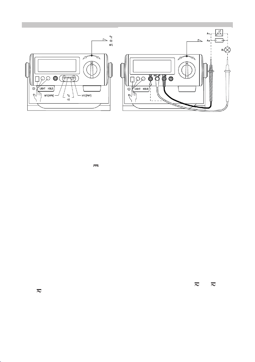
Capacitance Measurement
To measure capacitance, connect the meter as follows:
• Use the multi-purpose socket and connect to the V and mA μA terminals.
• Set the rotary switch to F.
• Connect the test leads across with the object being measured. The measured
value shows on the display.
• When measuring capacitance values larger than 600uF, it is normal for the meter
to require some time to stabilize.
• The LCD displays OL indicating the tested capacitor is shorted or it exceeds the
maximum range.
• When capacitance measurement has been completed, disconnect the test leads
from the device under test.
Note: The Meter displays a xed value which is the value of the meters own internal
circuitry. To ensure accuracy, it is necessary to subtract this value from the displayed
value when measuring small capacitors.
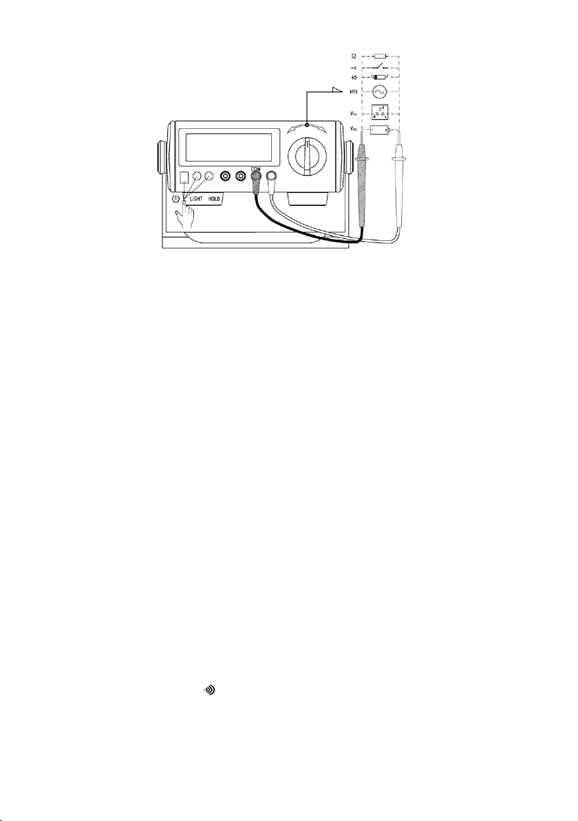
Frequency Measurement
Warning: To avoid the risk of personal injury, do not attempt to measure frequency with
voltage higher than 30V RMS.
To measure frequency, connect the meter as follows:
• Insert the red test lead into the Hz terminal and the black test lead into the COM
terminal.
• Set the rotary switch to Hz to select Frequency measurement mode.
• Connect the test leads across with the object being measured. The measured
value shows on the display.
• When frequency measurement is complete, disconnect the test leads from the
circuit under test.