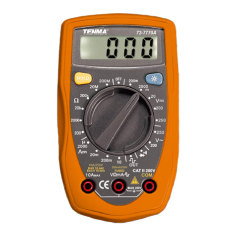
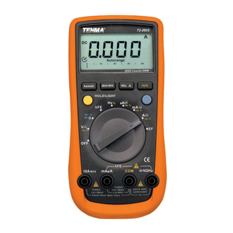
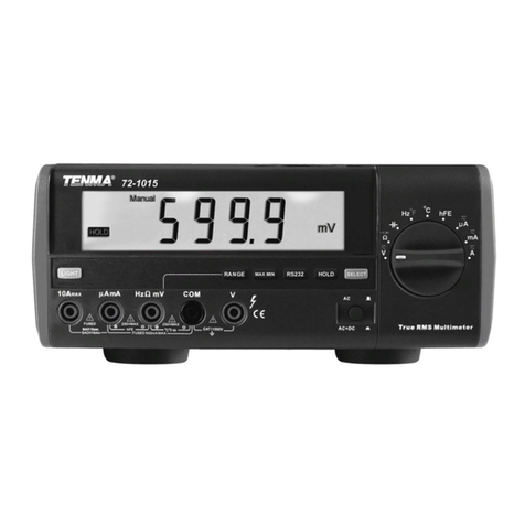
Tenma 72-10395 User manual
Other Tenma Multimeter manuals

Tenma
Tenma 72-1055 User manual
Tenma
Tenma 72-8715 User manual
Tenma
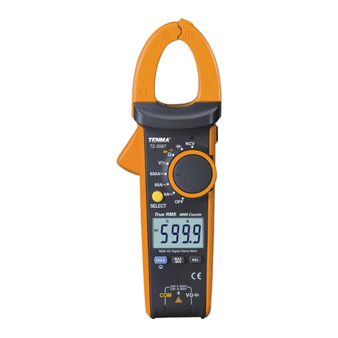
Tenma 72-3097 User manual

Tenma
Tenma 72-3540 User manual
Tenma
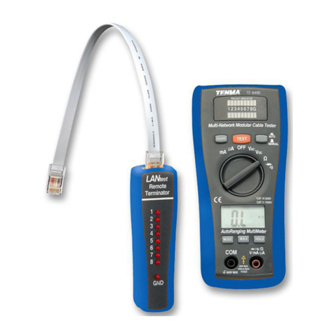
Tenma 72-8495 User manual
Tenma
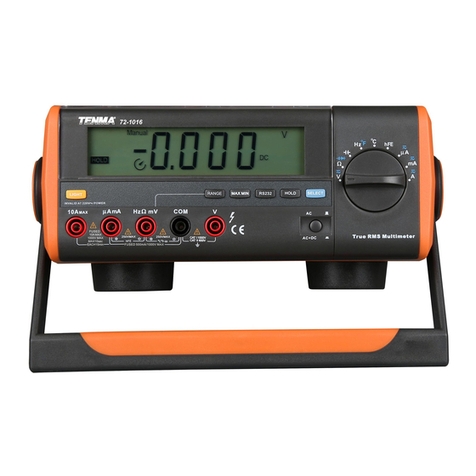
Tenma 72-1016 User manual
Tenma
Tenma 72-9380A User manual
Tenma
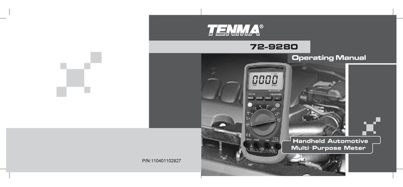
Tenma 72-9280 User manual

Tenma
Tenma 72-7930 User manual
Tenma
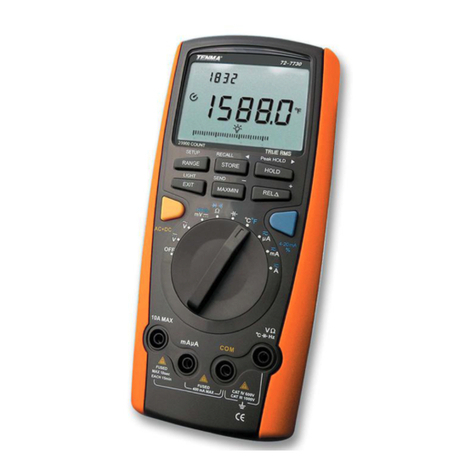
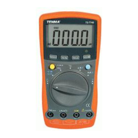
Tenma 72-7740 User manual

Tenma
Tenma 72-7780 User manual
Tenma
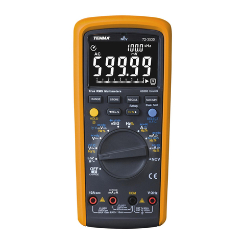
Tenma 72-3530 User manual
Tenma
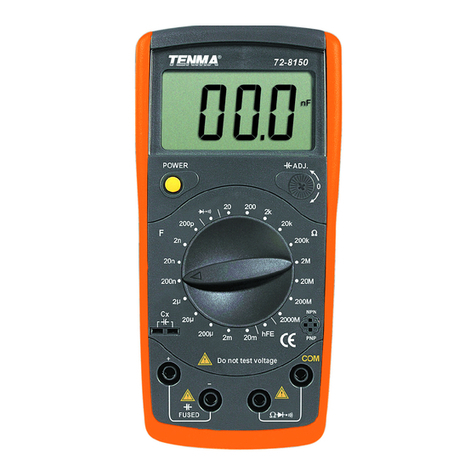
Tenma 72-8150 User manual
Tenma
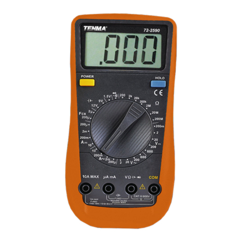
Tenma 72-2590 User manual
Tenma
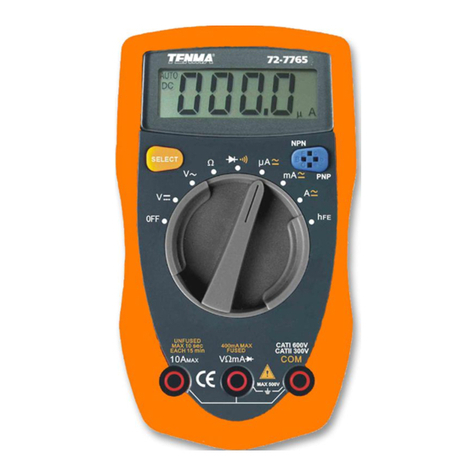
Tenma 72-7765 User manual

Tenma
Tenma 72-8155 User manual
Tenma
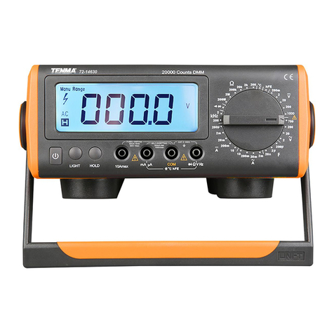
Tenma 72-14630 User manual
Tenma
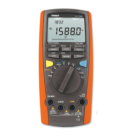
Tenma 72-7730A User manual

Tenma
Tenma 72-7720 User manual
Tenma
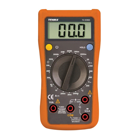
Tenma 72-10390A User manual
Popular Multimeter manuals by other brands

Gossen MetraWatt
Gossen MetraWatt METRAmax 6 operating instructions

PeakTech
PeakTech 4000 Procedure of calibration

YOKOGAWA
YOKOGAWA 90050B user manual

Gossen MetraWatt
Gossen MetraWatt METRALINE DMM16 operating instructions

Fluke
Fluke 8846A Programmer's manual

Tempo Communications
Tempo Communications MM200 instruction manual

