Tenma 72-3097 User manual

1
600A True RMS Digital Clamp
Meter
Model: 72-3097 & 72-3099

2
CONTENTS
Page Number Details
3 Important Safety Information
4 Product overview
4 Key Functions
5General Specication
5Electrical Specication
5 AC (Ã)
6 AC (A) (72-3099 only)
6AC Voltage (Ṽ)
6 DC Voltage (V)
6Resistance (Ω)
6Continuity Test
7Diode Test
7 Capacitance
7 Temperature (°C) (72-3099 only)
8 Frequency (Hz) (72-3099 only)
8 NCV
8 Operation - AC Measurement
9 DC Current Measurement (72-3099 only)
9 AC Voltage Measurement
10 DC Voltage Measurement
10 Resistance Measurement
11 Continuity Test
11 Diode Measurement
12 Capacitance Measurement
13 Frequency
13 Temperature Measurement (72-3099 only)
13 Non-contact AC Voltage Sensing NCV
14 Power Gear (off) & Automatic Shutdown
14 Battery Replacement
14 Cleaning & Maintenance

3
IMPORTANT SAFETY INFORMATION
• When using electrical appliances basic safety precautions should always be
followed.
• Check the clamp ammeter and test pen before use. If there is any damage or any
abnormalities, do not use it.
• Do not use the clamp ammeter if the battery cover and rear cap is not in place, as
there is a risk of electric shocking.
•Keep ngers within the scope of the test pen nger protection. Do not contact the
bare wire and connector, the unused input terminal or the circuit being measured
when the clamp ammeter is in operation.
• Ensure that function switches are set at the correct position prior to measurement.
Do not perform gear conversion in measurement to guard against damage to the
meter.
• Do not apply over 1000VDC or 750VAC between the clamp ammeter terminals
and ground, to guard against damage to the meter.
• Be careful in measuring RMS voltage higher than 30V DC or AC, as there will be
electric shocking.
• Do not measure voltage or current higher than the allowable input value. Set the
function range switch at the maximum range position if the scope of the measured
value cannot be dened.
• Before measurement of online resistance and diode or circuit on-off measurement,
the power to the circuits being measured must be switched off and all capacitors
should be completely discharged to assure measurement accuracy.
• When the LCD displays the low battery symbol, replace the battery immediately in
order to ensure measurement accuracy.
• Remove the battery when the clamp meter is not in use for a long period of time.
• Do not change the internal wiring in the clamp ammeter, in order to guard against
damage to the meter.
•Do not store or use the clamp ammeter in an explosive or ammable environment
with high temperature, high humidity or a strong electromagnetic eld.
• Clean the clamp meter case with a soft cloth and a neutral detergent.
• Do not use any chemicals, abrasives or solvents to avoid causing damage to the
instrument.

4
PRODUCT OVERVIEW
1. Clamp head: a device used to measure AC/DC current and
convert current into voltage.
2. Clamp body: designed for safe use and to protect the operator
from touching dangerous areas.
3. Clamp head pulling handle: press the trigger to open the clamp
head.
4. Dial switch: select the measurement function gear.
5. Function key: select basic functions.
6. LCD display area: displays the measured data and functional
symbols.
7. Measure input terminal: measure the signal input.
1. High Voltage 9. Diode
2. Low Battery 10. Circuit on-off measurement
3. Relative value 11. Auto range
4. Auto shutdown 12. Max/min measurement
5. Data hold 13. Non-contact AC voltage sensing
6. Unit 14. Frequency conversion
measurement
7. DC Signal 15. Temperature unit
8. AC Signal
KEY FUNCTIONS
SELECT
Press in order to choose. Press and hold the key and the LCD will display
“VFC” to enable frequency conversion signal measurement. It is only
valid for AC voltage 600V and AC measurement. Press and hold to block
frequency conversion signal measurement.
HOLD
Press this button once to enter data hold measurement mode and press
again to exit the mode.
Press and hold the button to turn the backlight on. If the button is not held
down within 15 seconds the backlight will turn off automatically.
MAX/
MIN
Press once and the LCD will display “MAX” and enter maximum
measurement mode.
Press again and the LCD will display “MIN” indicating minimum
measurement mode.
Press and hold the button to exit maximum/minimum value measurement.
It is only valid for AC voltage, AC current, resistance and temperature
measurement.
REL
With the exception of DC current gear, under the non-read back stored
record data mode, it is able to enter the relative measurement mode
with by pressing REL. The main display will show: measured value -
basic value. It is only valid for AC voltage, AC current, resistance and
capacitance measurement.
1
2
34
5
6
7

5
REL
(cont)
Press again to exit relative value measurement mode.
Under DC current gear measurement mode, press to enter clearing
mode and the LCD will display “∆”. Press again to exit clearing mode.
FLIGHT Press and hold this button to turn the torch function on.
Press the button once and the torch function will turn off.
GENERAL SPECIFICATION
LCD Maximum display 6000.
Polarity display Auto positive and negative polarity display. Overload
display: “OL” or “-OL”.
Low voltage display “Figure 1” indicates that the battery voltage is lower
than the working voltage.
Sampling rate About 3/s.
Sensor type Coil induction (72-3097)/Hall effect sensor (72-3099).
Text position error
An additional reading error of ±1.0% may result when
the power to be measured is not clamped at the
centre of the clamp head.
Impact resistance strength 1m fall impact.
Max. openness of clamp
head
30mm diameter, max. dimension of current conductor
to be measured: 30mm diameter.
Electromagnetic eld
impact
The applicaton of device near electromagnetic eld
may result in unstable display or inaccurate readings.
Power 3 AAA 1.5V zinc manganese batteries.
Dimensions 228mm x 77mm x 41mm.
Weight About 265g (inc. batteries).
Operating temperature
0°C to 30°C (no higher than 80% RH).
30°C to 40°C (no higher than 75% RH).
40°C to 50°C (no higher than 45% RH).
Storage temperature -20°C to 60°C (no higher than 80% RH).
ELECTRICAL SPECIFICATION
• Accuracy: ± (% + word number), one year calibration time.
• Ambient temperature: 23°C ± 5°C.
•Ambient humidity: ≤80% RH.
•Temperature coefcient: 0.1 x (accuracy)/°C.
AC (Ã)
Range Resolution Accuracy Overload protection
6.000A 0.001A ±(2.5% + 30)
600A60.00A 0.01A ±(2.5% + 5)
600.0A 0.1A
• Display: current true
value: applicable for
range from 10% to
100%.
• Frequency response:
50Hz~60Hz.

6
• The measurement accuracy of non-sinusoidal wave various frequency current
should be 5% higher than the former.
Range Resolution Accuracy Overload protection
60.00A 0.01A ± (2.5% + 5) 600A
600.0A 0.1A
AC (A) (72-3099 only)
• DCI base number
should be deleted by
the ZERO key.
AC VOLTAGE (Ṽ)
Range Resolution Accuracy Overload protection
6.000V 0.001V
± (1.2% + 5) 1000V DC
750V AC
60.00V 0.01V
600.0V 0.1V
750V 1V ± (1.5% + 5)
• Display: voltage true
value; applicable for
range from 10% to
100%.
• Voltage: input
impedance ≥10MΩ.
• Frequency response:
40~400Hz.
DC VOLTAGE (V)
Range Resolution Accuracy Overload protection
600.0mV 0.1mV ± (1.0% + 8)
1000V DC
750V AC
6.000V 0.001V ± (0.8% + 1)
60.00V 0.01V ± (0.8% + 3)
600.0V 0.1V
1000V 1V ± (1.0% + 3)
RESISTANCE (Ω)
Range Resolution Accuracy Overload protection
600.0Ω 0.1Ω ± (1.2% + 2)
1000V DC
750V AC
6.000kΩ 0.001kΩ
± (1.0% + 2)60.00kΩ 0.01kΩ
600.0kΩ 0.1kΩ
6.000MΩ 0.001MΩ ± (1.2% + 2)
60.00MΩ 0.01MΩ ± (1.5% + 5)
• Input impedance
≥10MΩ.
CONTINUITY TEST
Range Resolution Accuracy Overload protection
600.0Ω 0.1Ω
Buzzer beeps when
<30Ω 1000V DC
750V AC
Open circuit voltage
is about 1.2V

7
DIODE TEST ( )
Range Resolution Accuracy Overload protection
6.000V 0.001V
Open circuit voltage is about 3.3V,
measurable PN knot ≤3V positive
pressure drop value. Silicon PN
normal voltage value is about
0.5~0.8V.
100V DC
750V AC
CAPACITANCE
Range Resolution Accuracy Overload protection
99.99nF 0.01nF ± (4.0% + 25)
1000V DC
750V AC
999.9nF 0.1nF
± (4.0% + 5)
9.999µF 0.001µF
99.99µF 0.01µF
999.9µF 0.1µF
9.999mF 0.001mF ± (10%)
59.99mF 0.01mF For reference only
72-3097
Range Resolution Accuracy Overload protection
60.00nF 0.01nF ± (4.0% + 25)
1000V DC
750V AC
600.0nF 0.1nF
± (4.0% + 5)
6.000µF 0.001µF
60.00µF 0.01µF
600.0µF 0.1µF
6.000mF 0.001mF ± (10%)
60.00mF 0.01mF For reference only
72-3099
TEMPERATURE (°C) (72-3099 ONLY)
Range Resolution Accuracy Overload protection
-40°C~40°C
1°C ± (3.0% + 5)
1000V DC
750V AC
40°~400°C
400°C~1000°C ± (2.0% + 5)
-40°F~104
1°F ± (3.0% + 10)
104°F~752°F
752°F~1832°F ± (2.0% + 10)

8
FREQUENCY Hz (72-3099 ONLY)
Range Resolution Accuracy Overload protection
10Hz
1 MHz
0.01Hz
1kHz ± (0.1% + 4) 1000V DC
750V AC
~ ~
Requirement on input range:
•≤ 100kHz: 100mVrms ≤ input range ≤ 20Vrms > 100kHz ~ 1MHz: 200mVrms ≤
input range ≤ 20Vrms.
NCV
Range Accuracy
NCV ≥100Vrms; ≤10mm (LED/buzzer indication)
OPERATION - AC MEASUREMENT
• Push the switch to AC current gear. Then press the trigger to open the clamp
head to take the conductor to be measured, then slowly loosen the trigger until the
clamp head is completely closed.
• Make sure that the conductor to be measured is clamped at the centre of the
clamp head, otherwise it may result in an additional error.
Note: The clamp ammeter can only measure one current conductor. Measuring
two or more current conductors concurrently may result in wrong measurement
readings.
• Read the true value of AC directly from the display.
• Press and hold the SELECT key in AC gear to select VFC measurements and
measure frequency converter current (72-3099 only).
Note:
• Current measurement must be operated within 0°~40°C. If a positive reading is
achieved after measuring DC current, the current direction will go from up to down.
Do not loosen the trigger abruptly as the Hall component
is sometimes sensitive to magnets, heat, mechanical
stress and also to impact, which may cause short-time
reading variation.
• Ensure the conductor to be measured is clamped at the
centre of the clamp head. If it isn’t, an additional reading
error of ±1% may result.
• AC conversion adopts the AC coupling true RMS
response mode, sinusoidal input correction. The accuracy
of non-sinusoidal waves shall be adjusted as follows:
- Crest factor 1.4~2.0, accuracy should be increased
1.0%.
- Crest factor 2.0~2.5, accuracy should be increased
2.5%.
- Crest factor 2.5~3.0, accuracy should be increased
4.0%.

9
DC CURRENT MEASUREMENT (72-3099 ONLY)
• Push the switch to DC current gear. If the LCD display is not set to zero, press
REL to clear.
• After measuring the big current gear, the clamp head will be left with remanence
and the LCD will have base values.
• Press the trigger to open the clamp head and take the conductor to be measured,
then slowly loosen the trigger until the clamp head is completely closed.
• Ensure the conductor to be measured is clamped at the centre of the clamp head,
otherwise an error may occur.
• The clamp ammeter can only measure one current conductor. Measuring two
or more current conductors concurrently may result in incorrect measurement
readings.
• Directly read out the measured DC current value from the
display.
Note:
• Current measurement must be operated within 0°~40°C.
If a positive reading is achieved after measuring DC
current, the current direction will go from up to down. Do
not loosen the trigger abruptly as the Hall component is
sometimes sensitive to magnetization, heat, mechanical
stress and also to impact, which may cause short-time
reading variation.
• Ensure the conductor to be measured is clamped at the
centre of the clamp head. If it isn’t, an additional reading
error of ±1% may result.
AC VOLTAGE MEASUREMENT
• Insert the red test pen into the “V” jack and the black test pen into the “COM” jack.
• Push the function range switch to the AC voltage measurement gear and connect
the test pen in parallel with the power or load to be measured.
• Read the true value of the AC voltage from the display.
•Press and hold the SELECT key in AC voltage gear to
select VFC measurement and measure the frequency
converted voltage (72-3099 only).
• For 72-3099, pressing and holding the SELECT key
can select frequency measurements of AC voltage.
Note: the following conditions must be met when
reading frequency value:
input range ≥ range x 10%. (Testing range of
frequency gear at voltage gear is 40Hz-400Hz).
Note:
• Do not input voltage higher than AC 750V. It may be
feasible to measure higher voltage, but damage will
be caused to the meter.

10
• Pay attention to electric shocks when measuring high voltage.
• After completing all measurement operations, disconnect the test pen from the
measured circuit.
• When the measured voltage is higher than the safety voltage of 30V AC, the meter
LCD displays the high voltage warning prompt.
• When inputting overvoltage, higher than 750V AC gear range, the meter will
automatically sound intermittent buzzing and the high voltage warning prompt will
automatically ash.
• AC conversion adopts the AC coupling true RMS response mode, sinusoidal input
for correction.
• The accuracy of non-sinusoidal wave shall be adjusted as follows:
- Crest factor 1.4~2.0, accuracy should be increased 1.0%,
- Crest factor 2.0~2.5, accuracy should be increased 2.5%,
- Crest factor 2.5~3.0, accuracy should be increased 4.0%.
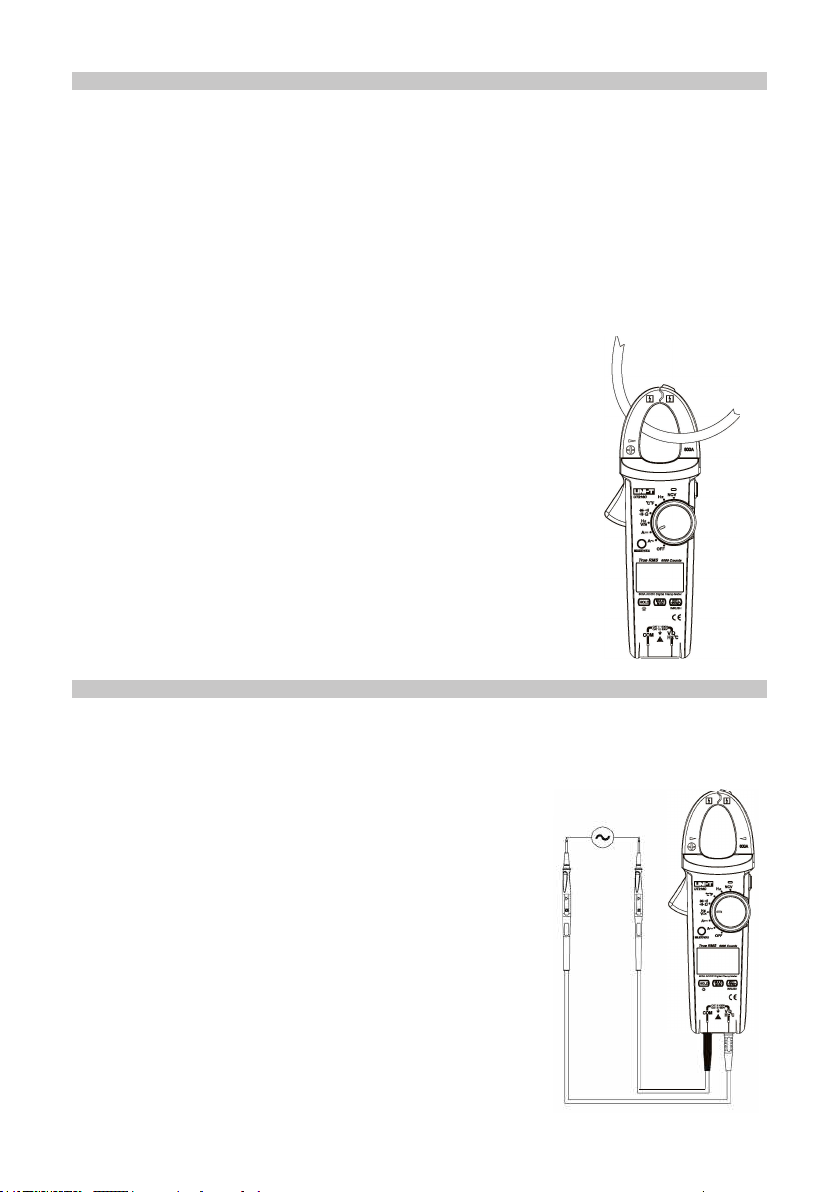
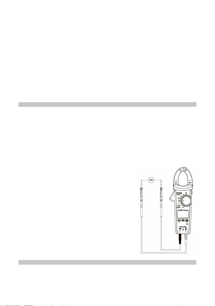
DC VOLTAGE MEASUREMENT
• Insert the red test pen into the “V” jack and the black test pen into the “COM” jack.
• Push the function range switch to the DC voltage measurement and connect the
test pen in parallel with the power or load to be measured.
• Directly read the measured resistance value from the display.
Note:
•Insert the red test pen into the “Ω” jack and the black test pen into the “COM” jack.
•Push the function range switch to the measurement gear “Ω”, press SELECT to
RESISTANCE MEASUREMENT
•
•
•
•
•
•
Do not input voltage higher than 1000V. It may be feasible to measure higher
voltage, but damage will be caused to the meter.
In order to obtain a precise reading when measuring at 600mV gear, the relative
measurement function can be adopted.
Firstly, input the test pen under the short-circuit
condition, press the REL button and read the
resistance measurement value. Afterwards, the meter
automatically deducts the test pen displayed value
under short-circuit condition.
Watch out for electric shocks when measuring high
voltage. After completing all measurement operations,
disconnect the test pen from the measured circuit.
When the measured voltage is higher than the safety
voltage of 30V DC, the meter LCD will display the
warning prompt.
When inputting overvoltage higher than 1000V
DC gear range, the meter will automatically sound
intermittent buzzing and the high voltage warning
prompt will automatically ash.

11
CONTINUITY TEST
•Insert the red test pen into the “Ω” jack and the black test pen into the “COM” jack.
• Push the function range switch to the measurement gear “ ”, press SELECT to
select circuit on-off measurement and connect the test pen in parallel with the two
terminals of measured circuit.
•When the measured resistance between the two terminals <30Ω, the circuit should
be deemed conductive and the buzzer will sound continuously.
•When resistance is ≥30Ω and ≤60Ω, the buzzer will not sound.
•When resistance is >60Ω, the buzzer will not sound.
• Directly read the measured resistance value loaded
by the circuit from the display.
Note:
• When checking on-line circuit on-off conditions, it is
required, prior to measurement, to switch off all power
in the measured circuit and discharge all residual
charges in the capacitor.
• With respect to the circuit on-off measurement,
open-circuit voltage is approximately -3.5V and range
should be 600Ω measurement gear.
• Do not input voltage higher than 30V DC or AC, as it
may cause personal injury.
• After completing all measurement operations,
disconnect the test pen from the measured circuit.
select resistance measurement Ω and connect the
test pen in parallel with the two terminals of measured
resistance.
• Directly read the measured resistance value from the
display.
Note:
• If the open circuit of resistance being measured
exceeds the maximum range of the meter, the display
will show “OL”.
• Before measuring resistance on-line, the power of
circuits being measured shall be powered off and all
capacitors will release residues of electric charges to
assure measurement accuracy.
DIODE MEASUREMENT
•Insert the red test pen into the “Ω” jack and the black test pen into the “COM” jack.
The polarity of the red and black test pen is respectively “+” and “-”.
• Push the function range switch to the measurement gear “ ”, select diode
measurement and directly read out the approximate forward direction PN junction
voltage.

12
• For silicon PN junction generally 500~800mV is
conrmed to be the normal value.
Note:
• “OL” will be displayed when the measured diode is
open-circuit or the polarity is inversely connected.
• Before measuring diode, the power circuits being
measured shall be powered off and all capacitors
shall release residues of electric charged to assure
the measurement accuracy,
• The test open-circuit voltage of diode is approximately
3.5V.
• Do not input voltage higher than 30V DC or AC, as it
may cause personal injury.
• After completing all measurement operations,
disconnect the test pen from the measured circuit.
CAPACITANCE MEASUREMENT
• Insert the red test pen into the “V” jack and the black test pen into the “COM”
jack. Measure by REL mode.
• Push the range switch to the measurement gear “ ”, press SELECT to select
“capacitance” and connect the test pen in parallel with the two terminals of
measured capacitance.
• Directly read out the capacitance value of the measured circuit from the display.
• It is recommended to carry out the capacitance measurement with test short line
input, thus reducing the impact caused by distributed capacitance.
Note:
•
•
•
•
•
•
If the measured capacitance is short circuited or capacitance exceeds the
maximum range of the meter, the display will show “OL”. Under capacitance
measurement mode, the simulation bar indicator is
forbidden.
It will take a longer time to achieve the correct reading
when measuring capacitance larger than 600µF.
To ensure the measurement accuracy, it is
recommended to discharge all residual charges in the
capacitor before the test.
Then, input the meter for measurement, which is
particularly important to the capacitor with high
voltage.
It is required to prevent damage to the meter and
personal injury.
After completing the measurement operation,
disconnect the test pen from the measured
capacitance.

13
FREQUENCY
• Insert the red test pen into the “Hz” jack and the black
test pen into the “COM” jack.
• Push the range switch to the measurement gear “Hz”
and connect the test pen in parallel with the signal
source to be measured.
• Directly read out the measured frequency value from
the display.
Note:
• It is required to meet the input range a when
measuring: ≤100kHz 100mVrms≤a≤20Vrms.
• Do not input frequency higher than 30Vrms, as it may
cause personal injury.
• After completing all measurement operations,
disconnect the test pen from the measured circuit.
TEMPERATURE MEASUREMENT (72-3099 only)
• Push the range switch to “°C °F” gear and the LCD will display “OL”, the short-
circuit test pen displays the room temperature.
• Insert the temperature K type socket into the corresponding hole.
• Place the temperature probe to detect the measured surface and several
seconds later, directly read out the measured Celsius
temperature value from the LCD.
• Press SELECT to select Fahrenheit temperature
measurement.
Note:
• The meter should not be operated in a place with
ambient temperature beyond the range 18°C to 28°C
as results can be affected, particularly evident in a low
temperature environment.
• Do not input voltage higher than 30V DC or AC, as it
may cause personal injury.
• After completing all measurement operations, remove
the temperature probe.
NON-CONTACT AC VOLTAGE SENSING NCV
• In order to sense whether there is AC voltage or
electromagnetic eld in this space, place the front end
of the clamp meter near to the conductor to be tested in
order to sense detection (distance <10mm).
•When the electric eld voltage is ≥ 100VAC, the LCD
will display “-”, which has four levels, “-”, “- -”, “- - -” and
“- - - -” subject to sensing voltage.
•The buzzer will continue to beep and the LED will ash
a red light.

14
POWER GEAR (OFF) & AUTOMATIC SHUTDOWN
• The instrument should be powered off.
• If you’re not turning the knob switch or pressing the key to the clamp ammeter
within the user-dened shutdown time (default 15 mins), the display will be blank
and enter the low power consumption dormant state.
• Press any key to wake up the meter.
• Press the SELECT key to start up the machine and the automatic shutdown
function is forbidden.
CLEANING & MAINTENANCE
•The clamp meter should be maintained and serviced by qualied personnel.
• Clean the outer case with a clean, dry cloth.
• Do not use any chemicals, abrasives or solvents that could cause damage to the
meter.
BATTERY REPLACEMENT
• Shut down the clamp meter and move away the test pen located at the input
terminal.
• Place the meter with the panel facing down
and unscrew the battery box screws, take off
the battery cap and remove the old batteries.
• Place the new batteries into the
compartment, observing the polarities.
• After installing the new batteries, replace the
battery cap and screw on the screws.
Made in China. www.premierfarnell.com
V.1.0
INFORMATION ON WASTE DISPOSAL FOR CONSUMERS OF
ELECTRICAL & ELECTRONIC EQUIPMENT.
This symbol indicate that separate collection of Waste Electrical and Electronic
Equipment (WEEE) or waste batteries is required. Do not dispose of these items with
general household waste. Separate for the treatment, recovery and recycling of the
materials used. Waste batteries can be returned to any waste battery recycling point
which are provided by most battery retailers. Contact your local authority for details of
the battery and WEEE recycling schemes available in your area.
This manual suits for next models
1
Table of contents
Other Tenma Multimeter manuals

Tenma
Tenma 72-7740 User manual

Tenma
Tenma 72-2605 User manual

Tenma
Tenma 72-8720 User manual

Tenma
Tenma 72-3530 User manual

Tenma
Tenma 72-2600 User manual

Tenma
Tenma UT202 User manual

Tenma
Tenma 72-2590 User manual

Tenma
Tenma 72-13430 User manual

Tenma
Tenma 72-10395 User manual

Tenma
Tenma 72-10395 User manual

Tenma
Tenma 72-10405 User manual

Tenma
Tenma 72-7228 User manual

Tenma
Tenma 72-9280 User manual

Tenma
Tenma 72-8155 User manual

Tenma
Tenma 72-1016 User manual

Tenma
Tenma 72-10465 User manual

Tenma
Tenma 72-14630 User manual

Tenma
Tenma 72-7224 User manual

Tenma
Tenma UT60C User manual

Tenma
Tenma 72-7780 User manual