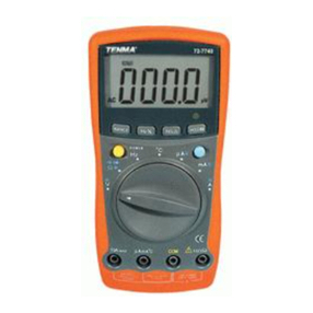
Tenma 72-2590 User manual

1
Model: 72-2590 and 72-2595
Digital Multimeter

2
Please read these instructions carefully before use and retain for future
reference.
This instrument is designed and manufactured in compliance with: G84793,
lEC61010-1, CAT III 600V, Pollution Degree 2 and Double Insulation standards.
• Check the test leads, probes and case insulation before using. If you nd any
breakage or abnormality, or you consider the device is broken, stop using the
device immediately.
• When using the test probes, keep your ngers behind the nger protection ring.
• Do not use the meter with the back cover open.
• Select appropriate test range for measurements.
• Ensure all inputs are less than the range selected otherwise it may cause electrical
shock or meter damage.
• Do not change the range selector position during voltage or current
measurements.
• Do not apply a voltage over 600V between COM terminal and ground.
• Take caution when working voltages are above 60V DC or 30V AC rms.
• Do not connect the meter to voltage signals when the range selector is on current,
resistance, diode or continuity range.
• When measuring current, each single measurement should be shorter than 10
seconds. For current values over 5A, the wait period between each measurement
must be longer than 15 minutes.
• When a measurement has been completed, disconnect the testing probes from
the circuit under test.
• Replace the batteries as soon as the low battery indicator appears on the display.
• Remove dead batteries from the meter or if it is not going to be used for a long
time.
• Never mix old and new batteries together, or different types of batteries.
• Never dispose of batteries in a re, or attempt to recharge ordinary batteries.
• Before replacing the battery, turn off the meter and disconnect all the test probes.
• To prolong battery life turn off the meter after use.
• CAT III: Measurement category III is for measurements performed in the building
installation. Examples are measurements on distribution boards, circuit-breakers,
and wiring, such as cables, bus-bars, junction boxes, switches and socket-outlets
in the xed installation, and equipment for industrial application and some other
equipment such as stationary motors with permanent connection to the xed
installation.
• Only use test leads and probes that are in compliance with IEC 61010-031, and
rated CAT III 600V.
SYMBOL GUIDE
Low battery Grounding Warning
Continuity Buzzer AC DC
Fuse Double insulated Diode
IMPORTANT SAFETY INFORMATION

3
WHAT’S INCLUDED
• Digital multimeter
• User manual
• Set of test leads
• K-type temperature probe (72-2595 only)
FUNCTIONS
1. POWER button
2. LCD Display
3. HOLD button
4. Range selector
5. Input terminals
OPERATING PARAMETERS
• Ambient temperature 23º± 5º
• Relative Humidity: <75%
DC VOLTAGE
Range Resolution Accuracy
200mV 100μV
±(0.5%+1)
2V 1mV
20V 10mV
200V 100mV
600V 1V ±(0.8%+2)
Note:
Input Impedance: 10MΩ for all ranges
AC VOLTAGE
Range Resolution Accuracy
2V 1mV
±(0.8%+3)20V 10mV
200V 100mV
600V 1V ±(1.5%+5)
Note:
• Input Impedance: 10MΩ for all ranges
• Frequency range: 45Hz-400Hz
• Overload protection: 600Vrms or 850Vpk-pk
• Display: Mean value (RMS value of sine wave)

4
AC VOLTAGE
Range Resolution Accuracy
72-2590 72-2595
200μA 0.1μA ±(0.8%+1) N/A
2mA 1μA ±(0.8%+1)
20mA 10μA N/A ±(0.8%+1)
200mA 100μA ±(1.5%+1)
10A 10mA ±(2.0%+5)
Notes:
• Overload protection.
• μA, mA input: 500mA/600V Φ6x32mm.
• A input: 10A/600V Φ6x32mm.
• Maximum input current: 10A (For current over 5A, measuring time must not
exceed 15 seconds).
• Measured voltage drop: 200mV for full range.
AC CURRENT
Range Resoluon Accuracy
72-2590 72-2595
200μA 0.1μA ±(1.0%+3) N/A
2mA 1μA ±(1.0%+3) N/A
20mA 10μA N/A ±(1.0%+3)
200mA 100μA ±(1.8%+3)
10A 10mA ±(3.0%+5)
Notes:
• Overload Protection
• uA, mA input: 500mA/600V Φ6x32mm.
• A input: 10A/600V Φ6x32mm.
• Maximum input current: 10A (For current over 5A, measurement time must not
exceed 10 seconds and the wait period between each measurement must be
longer than 15 minutes).
• Measured voltage drop: 200mV for full range.
• Display: Mean value (RMS value of sine wave).

5
RESISTANCE
Range Resoluon Accuracy
72-2590 72-2595
200Ω 0.1Ω ±(1.2%+2)
2kΩ 1Ω
±(1.0%+2)20kΩ 10Ω
200kΩ 100Ω
2MΩ 1kΩ ±(1.2%+2)
20MΩ 10kΩ ±(1.5%+2)
200MΩ 100kΩ ±[5.0%(reading-10)+10)] N/A
Notes
• Open-circuit voltage: ≤ 700mV (The open circuit voltage is about 2.9V at 200MΩ
range).
• Overload protection: 600Vrms DC or AC for all ranges.
• Relative Humidity <65% for measurements at 200MΩ range.
CAPACITANCE
Range Resolution Accuracy
72-2590 72-2595
2nF 1pF N/A ±(4.0%+3)
20nF 10pF N/A ±(4.0%+3)
200nF 100pF N/A ±(4.0%+3)
2μF 1nF ±(4.0%+3)
200μF 100nF ≤50μF ±(5.0%+4) >50μF, for reference only
Note: Testing signal is about 200Hz, 40mVrms.
TEMPERATURE (72-2595 ONLY)
Range Resolution Accuracy
TEMP ºC
(-40ºC~1000ºC)
-40ºC~0ºC
1ºC
±(3%+9)
0ºC~400ºC ±(1%+5)
400ºC ~1000ºC ±(2%+10)
TEM ºF
(-40ºF~1832ºF)
-40ºF~3ºF
2ºF
±(3%+10)
32ºF~75ºF ±(1%+8)
752ºF~1832ºF ±(2%+18)

6
CONTINUITY AND DIODE TEST
Range Description Testing Condition
Displays the forward voltage of
the diode (approximate value) in
mV.
Forward DC current is about
1mA.
Reverse DC voltage is about
2.8V.
When resistance ≤10Ω, the
buzzer beeps and an approximate
resistance value in Ω displays.
Open circuit voltage is about
2.8V.
Note: Overload protection, 600Vrms DC or AC.
BATTERY TEST (72-2590 ONLY)
Range Resolution Accuracy Description
12V 10mV
±(2.5%+2)
Built-in load resistance: 240Ω
9V 10mV Built-in load resistance: 1.8kΩ
1.5V 1mV Built-in load resistance: 30Ω
Note: Overload protection 500mA/600V fuse.
OPERATION
Measuring DC Voltage
• Insert the test leads into the input terminals (red to V and black to COM).
• Turn the range selector to range.
• Connect the test probes with the power or load being measured in parallel, and the
polarity of the point touched by the red test probe displays.
B. Measuring AC Voltage
• Insert the test leads into the input terminals (red to V and black to COM).
• Turn the range selector to a range, and connect the test probes to the power or
load being measured in parallel.
Notes:
• If the voltage to be measured is unknown, choose the maximum measuring range
(600V) and reduce it step by step until a satisfactory reading is obtained.
• Disconnect from the circuit under test when changing the range.
• If the Display shows “OL”, it indicates the measured voltage is out of range. In this
case, turn the range selector to a higher range.
• “ ” on the meter indicates that inputting a voltage higher than 600V is not
allowed. Otherwise, the meter will be damaged.
• Special attention should be given to avoid electrical shock when measuring high
voltage.

7
Measuring DC Current
• Insert the black test lead into COM terminal. If the current under test is ≤ 200mA,
insert the red test lead into the mA terminal. If the current is higher, insert the red
test lead into 10A terminal.
• Turn the range selector to range, and connect the test probes in series with
the circuit to be measured. The polarity of the point touched by the red test probe
together with the measured value is displayed.
Measuring AC Current
• Insert the black test lead into COM terminal. If the current under test ≤ 200mA,
insert the red test lead into mA terminal. If the current is higher, insert the red test
lead into 10A terminal.
• Turn the range selector to a
~
range, and connect the test probes with the circuit
being measured in series.
Notes:
• If the current to be measured is unknown, choose the maximum measuring range
(10A) and reduce it step by step until a satisfactory reading is obtained.
• Disconnect from the circuit under test when changing the range.
• If the display only shows “OL”, it indicates the measured current is out of range. In
this case, turn the range selector to a higher range.
• “ ” on the meter indicates that the maximum input current is 200mA. The built-in
fuse of 500mA/600V Φ6 x 32mm can effectively protect the circuit from burn-out.
The 10A range uses a fuse of 10A/600V Φ6 x32mm for protection.
Measuring Resistance
• Insert the test leads into the input terminals (red to Ω and black to COM).
• Turn the range selector to a Ω range, and connect the test probes to the resistor
being measured.
Notes
• If the measured resistance is out of the range selected, “OL” will be displayed and
you should select a higher range. It normally takes several seconds to display a
stable reading in a high-resistance (>1MΩ) measurement.
• When there is no input, such as in open-circuit condition, the instrument will
display “OL”.
• When making an in circuit measurement, disconnect all power supplies and
discharge all the capacitors.
• In 200MΩ range, a 10-digit reading is produced on a short circuit. It should be
subtracted from the measured value. For instance, when you measure 100MΩ, the
meter will display 101.0, subtract 10 digits from 101.0 to get the precise reading.
•
Measuring Capacitance
• Before connecting to the capacitor to be tested, note that the zeroing after range
change takes some time and the existing drift reading cannot inuence the testing
precision.
• Insert the test leads into the centre pair of terminals marked .
• Turn the range selector to Fcx range, and connect the test probes to the capacitor
under test.
• The capacitance is displayed.
8
Notes
• Although the capacitance ranges have been protected internally, you must fully
discharge the capacitor to be measured to avoid possible meter damage and
measuring errors.
• During large-capacitance measurement, it will take some time to get a stable
reading.
• Unit, 1000pF=1nF, 1000nF=1μF
Measuring Temperature (72-2595 only)
• Insert the test probe banana plugs into the input terminals (red to mA and black to
COM).
• Turn the range selector to ºC or ºF range, and the LCD displays the ambient
temperature.
• Place the probe near the object being measured.
• Read the measured temperature directly from the Display in ºC or ºF.
Testing Diodes and Continuity
• Insert the test leads into the input terminals (red to and black to COM, the
polarity of the red test lead is “+”). Then turn the range selector to range.
• Connect the test probes with the diode being tested. The reading obtained is the
approximate value of the forward voltage drop.
• Connect the test probes with the circuit under test, if the resistance between the
two tested points is <10Ω, the built-in buzzer sounds.
•
Battery Test (72-2590 only)
• Insert the test leads into the input terminals (red to and black to COM).
• Turn the range selector to a range.
• Connect the test probes with the battery being measured in series and ensure the
polarity is correct (red with “+”, black with “-”).
• The measured value shows on the display, which is the voltage between the
cathode and anode of the battery.
Note: When battery testing has been completed, disconnect the test probes from the
battery under test.
Auto Power Off
• The meter features an Auto Power Off function. It will power off automatically
after 15 minutes inactivity and enter the sleep mode which reduces battery power
consumption.
• If you want to power on the meter again, press the POWER button twice.

9
BATTERY REPLACEMENT
Warning: Only replace the battery after the test leads are removed and the power is off.
To replace the battery,
• Unscrew and remove the battery cover.
• Replace the battery with a new 9V battery of the same
type.
• Ret the cover.
• Clean the meter with a clean, soft cloth.
• Do not use any chemicals, abrasives or solvents that could damage the meter.
CLEANING
Battery
Screw

10
INFORMATION ON WASTE DISPOSAL FOR CONSUMERS OF
ELECTRICAL & ELECTRONIC EQUIPMENT
These symbols indicate that separate collection of Waste Electrical and Electronic Equipment
(WEEE) or waste batteries is required. Do not dispose of these items with general household
waste. Separate for the treatment, recovery and recycling of the materials used. Waste batteries
can be returned to any waste battery recycling point which are provided by most battery retailers.
Contact your local authority for details of the battery and WEEE recycling schemes available in
your area.
Made in China. PR2 9PP
Man Rev 1.0
This manual suits for next models
1
Table of contents
Other Tenma Multimeter manuals

Tenma
Tenma 72-8155 User manual

Tenma
Tenma TEN01061 User manual

Tenma
Tenma 72-8155 User manual

Tenma
Tenma 72-3540 User manual

Tenma
Tenma 72-7720 User manual

Tenma
Tenma 72-8720 User manual

Tenma
Tenma 72-8495 User manual

Tenma
Tenma 72-1055 User manual

Tenma
Tenma 72-10405 User manual

Tenma
Tenma 72-2600 User manual