Tenma AT-90DH-EU User manual

www.element14.com
www.farnell.com
www.newark.com
www.cpc.co.uk
TM
TM
Page <1> V1.023/08/18
ESD Safe Soldering Station
AT-90DH-EU & AT-90DH-UK
User Manual

www.element14.com
www.farnell.com
www.newark.com
www.cpc.co.uk
TM
TM
Page <2> V1.023/08/18
Please read this manual before operating the equipment.
Keep manual in accessible place for future reference.
What’s Included
Control Unit 1 No.
Soldering Iron 1 No.
Soldering Iron Holder 1 No.
Power Cord (UK or EU) 1 No.
Cleaning Sponge 1 No.
User Manual
Safety Precautions
• This product is meant for use by trained and qualied personnel only. Keep away from children
• Do not dis-assemble the control unit. There are no user serviceable parts
• Do not use the soldering station in the vicinity of ammable material
• Use appropriate safety gear and exercise caution while using this soldering station
• Do not touch the soldering tip as the temperature can be 100°C to 500°C when in use
• User proper power cord
• For changing the soldering tip, ensure that the power supply is turned off and allow sufcient time for the tip to cool down.
• The soldering tip should be cleaned by wiping it on the cleaning sponge provided. This will help get rid of the burnt solder
or uxes that cause oxidation on the soldering tip. Not cleaning the tip might lead to improper soldering.
Specications
Input Voltage 220V AC ±10% 50Hz
Plug Type UK, EU
Power Consumption 90W (Max.)
Temperature 100 ~ 500°C (212 ~ 932°F)
Temperature-correcting Range -50 ~ +50°C (-58 ~ +122°F)
Heater Voltage 24V AC
Temperature Stability ±2°C (Still air and no load)
Temperature Accuracy ±10°C
Setting Mode Keying adjustment and immediate access
Password Scope 001 ~ 999
Dormant Time 1 ~ 99minutes (No dormancy at the point of 0 minute)
Dormant Temperature 200°C (temperature at the tip of soldering iron in the dormant state)
Tip to Ground Impedance < 2Ω
Tip to Ground Voltage < 2mV
Display LCD
*Specications are subject to change without prior notice.

www.element14.com
www.farnell.com
www.newark.com
www.cpc.co.uk
TM
TM
Page <3> V1.023/08/18
Features:
• HD LCD, backlight LCD, visualized process control and easy to operate.
• Silver alloy as heat conducting material, heat exchange mode, and very fast temperature returning.
• Temperature rises to 350°C in 10 seconds after starting up.
• Immediate temperature access function and quick switch of service temperature.
• Auto sleep and password locking.
• Separate design between soldering iron and heating core, thus saving on use-cost.
• Handy handgrip and comfort to use.
• Fault display warning function.
Product photos
1. Soldering iron
2. Iron stand
3. Key “1”
4. Key “2”
5. LCD display
6. Key “3”
7. Key “▲”
8. Key “▼”
9. Power switch
10. Air socket
LCD display
1. SET: Set Temperature
2. REAL: Real Temperature
3. CAL: Calibration Temperature
4. Preset temperature of shortcut channel 11, when locked that will display “---”
5. Preset temperature of shortcut channel 12,when locked that will display “LDC”

www.element14.com
www.farnell.com
www.newark.com
www.cpc.co.uk
TM
TM
Page <4> V1.023/08/18
6. Preset temperature of shortcut channel 13,when locked that will display “---”
7. Temperature Status Bar
8. °C display
9. °F display
10. Temperature display
Operation Instructions
1. Connections
• Connect the cord assembly to the receptacle.
• Place the soldering iron in the iron holder.
• Plug the power cord rst into the power supply, then into a properly grounded outlet.
2. Power on
Connecting the socket on the back panel to the plug and make the power switch on. LED displays the set temperature, “Set”
appearing. Three seconds later, “Real” can be viewed, and LED displays the real temperature. Meanwhile temperature Unit °C
or °F appear at the upper right corner.
Default temperature unit is °C.
(picture one and picture two)
3. Shortcut temperature preset
When the machine works, press key “▼” or key “▲” (picture 3) to adjust the temperature. When “SET” lights, press and hold
the “▲” or key “▼” until the temperature readout ashes, stop and store a desired temperature.

www.element14.com
www.farnell.com
www.newark.com
www.cpc.co.uk
TM
TM
Page <5> V1.023/08/18
4. Shortcut temperature presets
When the machine works right, press key 1, key 2 or key 3 (picture 5), you can get the temperature setted before and use them
for the current working condition. When the machine works right, press key 1 , key 2 or key 3 (> 3 seconds), you can make the
current temperature as the shortcut one and stored at channel! and channel 2 and channel 3.
5. Temperature Calibration
When replacing the heating element or soldering tip, you need to calibrate the temperature, press “▲” “▼”at the same
time(picture 6),enter the mode of setting program, you can see from picture 7
When under the programmable mode, press key” 1 “(picture &), enter the mode of temperature calibration, “CAL” will light and
show the calibrated number last time, see from picture 9 (the calibration number is 0°C)...
Under the programmable mode, press “▲” or “▼” (picture 5), you can adjust the calibrated temperature, the range of calibration
(-50°C ~ 50°C) ( -58°F ~ 122°F). When the real temperature is lower than the display temperature ,enter minus temperature
difference value. When the real temperature is higher than the display temperature, enter the positive temperature difference
value. e.g. real temperature is 200°C display temperature is 220°C, then calibrated temperature is -20°C.
6. Change of the soldering mode
As to the different needs of the soldering mode, AT90DH has three different soldering mode to deal with the different needs,
you don’t need to buy other soldering equipment.
The setting method is as follows:
Press “▲”and “▼” at the same time (picture 6), enter into programming mode (picture 7).
Under programming mode, press “2”(picture 10), enter into soldering setting mode when “Mode” displays, it shows current
working mode. (Picture 11).
Under power setting mode, press “▲” or “▼”, adjust the power, and then press “2” to save. (Picture 12-Mode 1).

www.element14.com
www.farnell.com
www.newark.com
www.cpc.co.uk
TM
TM
Page <6> V1.023/08/18
Mode 0: Suitable for SMT, small welding work, in which temperature and its stability is highly required.
Mode 1: Suitable for welding work with different welding spots at the same time, back to temperature quickly.
Mode 2: Suitable for welding work with large amount of tin used, such as welding terminals, back to temperature very quickly,
large dynamic temperature range.
Attention: Original mode is Mode 1.
7. Sleeping mode setting
Sleeping power-off / power-on function and sleeping time can be set separately, which ensures energy saving and energy
consumption reducing.
Setting method:
Press “▲”and “▼” at the same time (picture 6), enter into programming mode (picture 7).
Under programming mode, press “2” (picture 10), or press”2” for 3 times continuously, then enter into sleeping setting mode
(picture 13-sleeping mode is off).
Under sleeping setting mode, press “▲” or “▼” (picture 5), input sleeping time (minute), then press “2” to save (picture 14,
sleeping time is 10 minutes).
If the sleeping mode is on and there is, no welding work or any operation in set time, the device will be in sleeping
(Mode2-no sleeping) and work in 200°C. If temperature is below 200°C, sleeping function won’t be activated.
Under sleeping mode, press any key to restart the device, and it can work under previous temperature.
Attention: Original mode- Sleeping status is off
8. Password-locked setting
This device is added with password-locked function for the convenience of equipment management for production line. When
the unit is locked, users can’t alter the settings without password.
Setting method:
8.1. Press “▲”and “▼” at the same time (picture 6), enter into programming mode (picture 7).
8.2. Under programming mode, press “3” (picture 15), enter into password-locked setting, current display is like picture
16( password locked on). picture 17 ( password locked off)

www.element14.com
www.farnell.com
www.newark.com
www.cpc.co.uk
TM
TM
Page <7> V1.023/08/18
8.3. Password setting:
When password is locked on, press “▲” or “▼” ( picture 3), input rst password, and then press “3” to conrm, like diagram 18.
When press “▲” or “▼”, input the password again, new password is OK, then press “3” to conrm and save.
New password is effected after restarting the device, any operation except reset password can’t be done work now (picture 13).
8.4. Password changing
Before changing, the device must be locked off. (picture 17).
Press “▲” or “▼”, input new password and press “3” to conrm. If password is right, display like picture 20, wrong like picture 21.
When the device is locked off, set new password like before. New password works after device restarting.
8.5. Password on or off function
Under the state of right password inputting, input new password “0” and password is clear after restarting the machine.
Note: When forget password, press “REST” (refer to “part 10 of exploded-view”), to clear password or unlock the password in
specied customer centre.
9. Fahrenheit and Celsius display
Fahrenheit and Celsius can be switched. When power off, press “2” to start the device, then nish switching.
10. Key-pressing sound and fault alarming function
AT90DH has key-pressing sound and fault alarm function. It can be turned on or off according to customer needs.
• Setting. When power off, press “▲”and “▼” simultaneously to restart the device, function is opened or closed.
• After starting key-pressing sound function, any valid key-pressing will be accompanied with key-pressing tone. Fault alarming
when failure occurs.
11. Trouble shooting tips.
When the device does not heat, “H-E” displays (picture 22), accompanied with alarming of every 5 seconds (when opening fault
alarming function). Maybe heating element or relevant parts of circuit damages, check and replace heating element.

www.element14.com
www.farnell.com
www.newark.com
www.cpc.co.uk
TM
TM
Page <8> V1.023/08/18
Important Notice : This data sheet and its contents (the “Information”) belong to the members of the Premier Farnell group of companies (the “Group”) or are licensed to it. No licence is granted
for the use of it other than for information purposes in connection with the products to which it relates. No licence of any intellectual property rights is granted. The Information is subject to change
without notice and replaces all data sheets previously supplied. The Information supplied is believed to be accurate but the Group assumes no responsibility for its accuracy or completeness, any
error in or omission from it or for any use made of it. Users of this data sheet should check for themselves the Information and the suitability of the products for their purpose and not make any
assumptions based on information included or omitted. Liability for loss or damage resulting from any reliance on the Information or use of it (including liability resulting from negligence or where the
Group was aware of the possibility of such loss or damage arising) is excluded. This will not operate to limit or restrict the Group’s liability for death or personal injury resulting from its negligence.
Tenma is the registered trademark of the Group. © Premier Farnell Limited 2016.
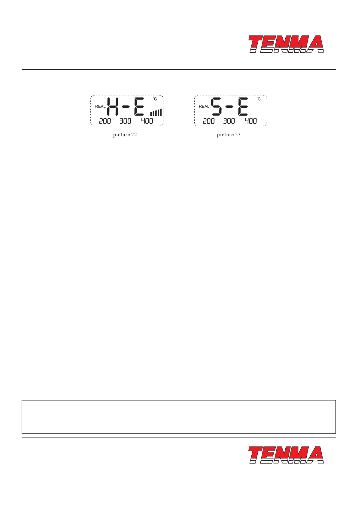
When “S - E” displays, accompanied with alarming of every 5 seconds (when opening fault alarming function). Maybe sensor
or relevant parts of circuit damages, check and replace sensor.
No any display on the screen, check power cord and re-connect.
Soldering tip is over - temperature or low - temperature, damaged or calibrated, please refer to “temperature calibration” or
replace the tip.
If there are illegible symbols, restart the machine.
When failure happens on the machine, repaired by only specied maintenance person or highly qualied technical personnel.
12. Soldering Tip Care and Use
a. Tip Temperature
High soldering temperatures can degrade the tip
Use the lowest possible soldering temperature. The excellent thermal recovery characteristics ensure efcient and effective
soldering even at low temperatures
When not in use, do not leave the soldering iron on at a high temperature as the tip’s solder plating will get covered by oxide,
reduction it’s heat conductivity
b. Cleaning
Clean the tip regularly with a cleaning sponge, as oxides and carbides from the solder and ux can form impurities on the tip.
These impurities can result in defective joints or reduce the tip’s heat conductivity
When using the soldering iron continuously, be sure to loosen the tip and remove all oxides at least once a week. This helps
prevent seizure and reduction of the tip temperature
After use, wipe the tip clean and coat with fresh solder. This helps prevent tip oxidation.
13. Changing the Soldering Tip
a. Always turn the power OFF when removing or inserting a soldering tip
b. Let the tip to cool down to room temperature before holding it with heat resistant pads
c. Loosen nut (1 in diagram 7)
d. Pull out the shaft of the soldering iron (2 in diagram 7)
e. Remove the old soldering tip and replace with new one (3 in diagram 7)
f. Reverse the process to secure the soldering tip
g. Preferred Soldering Tips : 21-10140, 21-10142, 21-10144, 21-10146, 21-10148, 21-10150, 21-10152, 21-10154, 21-10156,
21-10158
This manual suits for next models
1
Table of contents
Other Tenma Soldering Gun manuals