Tenma at90dh User manual

www.element14.com
www.farnell.com
www.newark.com
www.cpc.co.uk
www.mcmelectronics.com
TM
TM
Page <1> V1.028/03/16
AT90DH Soldering Station
User’s Manual
AT-90DH is a soldering station which has big power consumption and is particularly designed for lead-free soldering. It is
used for SMD electronic components’ soldering and de-soldering in factory or workbench.
In this instruction manual, “Warning” and “Caution” are dened as follows.
!WARNINGS:
Warning : Use only original manufacture’s specied heating element for the included iron.
Misuse may potentially cause injury to user or physical damage to the objects involved. For your own safety, be sure to
comply with these precautions.
Caution:
• Before using this unit, make sure to comply with the cautioned measurements to protect the user against the risks of elec-
tric shock, injury, re or other damage.
• To ensure use safety, use only the original parts manufactured specially for this unit.
Non-authorized replacement parts may cause damage and void all product warranties and liabilities.
• Maintenance should only performed by a qualied technician appointed by the manufacturer. Contact your distributor for
details.
• When power is on, the tip temperature is between; 100°C (°F) and 500°C (°F)
• Since mishandling may lead to burns or re, be sure to comply with the following precautions.
• Do not touch the metallic parts near the tip.
• Do not use the product near ammable items.
• Advise other people in the work area: the unit can reach a very high temperature and should be considered potentially
dangerous.
• Turn the power off when the unit is not being used or supervised.
• Before replacing parts or storing the unit, turn the power off and allow the unit to cool down to room temperature.
• To prevent damage to the unit and ensure a safe working environment, be sure to comply with the following precautions.
• Do not use the unit for application other than soldering and de-soldering.
• Do not rap the soldering iron against the workbench to shake off residual solder, or otherwise subject the iron to
severe shocks.
• Do not modify the unit.
• Use only genuine factory replacement parts.
• Do not allow the unit to get set or otherwise subject it to liquids. Do not use with wet hands or wet surface.
• The soldering process will produce smoke, so make sure the area is well ventilated.
• When using the unit, do not do anything that may cause bodily harm or physical damage.
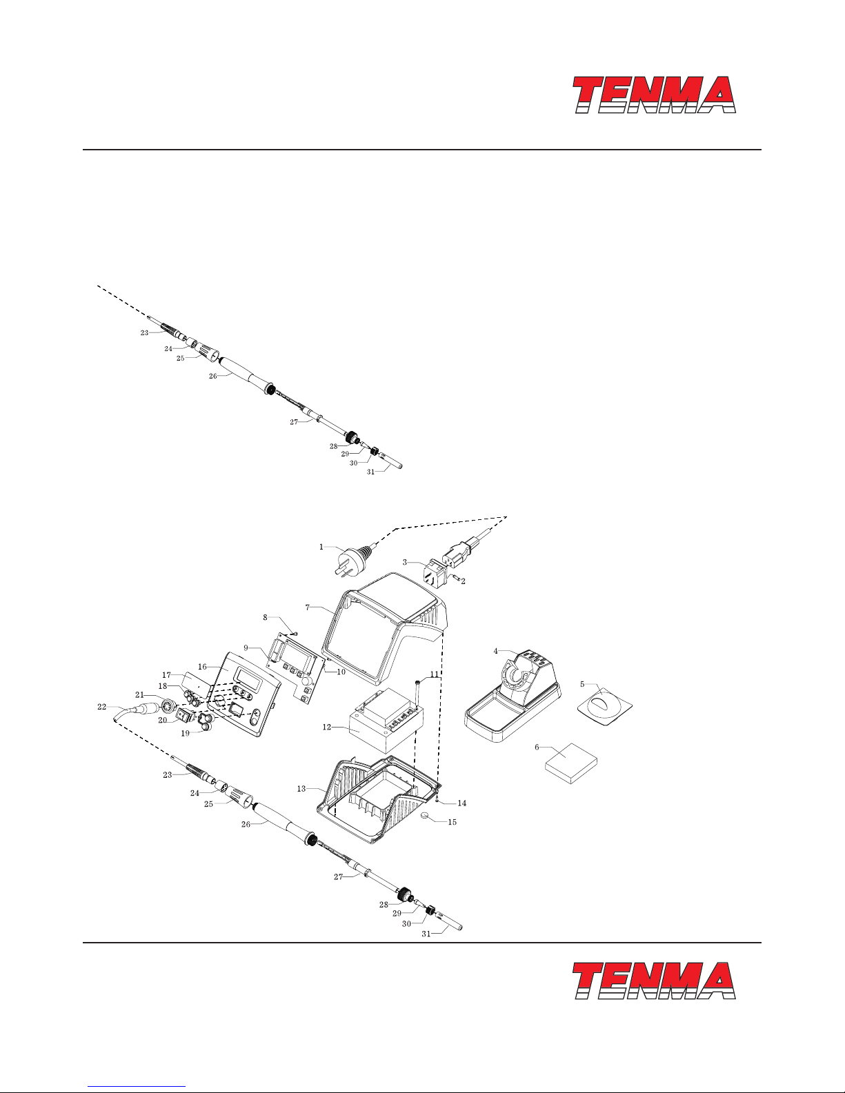
Packing List:
ATTEN90DH main Unit 1 unit
Iron stand (with sponge) 1 set
Soldering iron 1 pc
Power plug 1 pc
Manual 1 copy

www.element14.com
www.farnell.com
www.newark.com
www.cpc.co.uk
www.mcmelectronics.com
TM
TM
Page <2> V1.028/03/16
AT90DH Soldering Station
User’s Manual
Power Consumption 90W
Input Voltage 220V AC ±10% 50Hz (110V selectable)
Output Voltage 24V AC
Temperature Range 100 ~ 500°C (212 ~ 932°F)
Temperature-correcting Range -50 ~ +50°C (-58 ~ +122°F)
Temperature Stability ±2°C (Still air and no load)
Temperature Accuracy ±10°C
Setting Mode Keying adjustment and immediate access
Password Scope 001 ~ 999
Dormant Time 1 ~ 99minutes (No dormancy at the point of 0 minute)
Dormant Temperature 200°C (temperature at the tip of soldering iron in the
dormant state)
Tip to Ground Impedance <2Ω
Tip to Ground Voltage <2mV
Physical Dimension of
Principal Machine 175(L) × 155(W) × 95(H)mm
Weight Approximately. 2.3kg
Specications:
*The specications above is subject to further changes.
Features:
• HD LCD, backlight LCD, visualized process control and easy to operate.
• Silver alloy as heat conducting material, heat exchange mode, and very fast temperature returning.
• Temperature rises to 350°C in 10 seconds after starting up.
• Immediate temperature access function and quick switch of service temperature.
• Auto sleep and password locking.
• Separate design between soldering iron and heating core, thus saving on use-cost.
• Handy handgrip and comfort to use.
• Fault display warning function.
Product photos
1. Soldering iron
2. Iron stand
3. Key “1”
4. Key “2”
5. LCD display
6. Key “3”
7. Key “▲”
8. Key “▼”
9. Power switch
10. Air socket

www.element14.com
www.farnell.com
www.newark.com
www.cpc.co.uk
www.mcmelectronics.com
TM
TM
Page <3> V1.028/03/16
AT90DH Soldering Station
User’s Manual
LCD display
Introduction for LCD display:
1. SET: Set Temperature
2. REAL: Real Temperature
3. CAL: Calibration Temperature
4. Preset temperature of shortcut channel 11, when locked that will display “---”
5. Preset temperature of shortcut channel 12,when locked that will display “LDC”
6. Preset temperature of shortcut channel 13,when locked that will display “---”
7. Temperature Status Bar
8. °C display
9. °F display
10. Temperature display
Operation Instructions:
1. Connections
• Connect the cord assembly to the receptacle.
• Place the soldering iron in the iron holder.
• Plug the power cord rst into the power supply, then into a properly grounded outlet.
2. Power on
Connecting the socket on the back panel to the plug and make the power switch on. LED displays the set temperature,
“Set” appearing. Three seconds later, “Real” can be viewed, and LED displays the real temperature. Meanwhile temperature
Unit °C or °F appear at the upper right corner.

www.element14.com
www.farnell.com
www.newark.com
www.cpc.co.uk
www.mcmelectronics.com
TM
TM
Page <4> V1.028/03/16
AT90DH Soldering Station
User’s Manual
Default temperature unit is °C.
(picture one and picture two)
3. Shortcut temperature preset
When the machine works, press key “▼” or key “▲” (picture 3) to adjust the temperature. When “SET” lights, press and
hold the “▲” or key “▼” until the temperature readout ashes, stop and store a desired temperature.
4. Shortcut temperature presets
When the machine works right, press key 1, key 2 or key 3 (picture 5), you can get the temperature setted before and use
them for the current working condition. When the machine works right, press key 1 , key 2 or key 3 (> 3 seconds), you can
make the current temperature as the shortcut one and stored at channel! and channel 2 and channel 3.
5. Temperature Calibration
When replacing the heating element or soldering tip, you need to calibrate the temperature, press “▲” “▼”at the same
time(picture 6),enter the mode of setting program, you can see from picture 7

www.element14.com
www.farnell.com
www.newark.com
www.cpc.co.uk
www.mcmelectronics.com
TM
TM
Page <5> V1.028/03/16
AT90DH Soldering Station
User’s Manual
When under the programmable mode, press key” 1 “(picture &), enter the mode of temperature calibration, “CAL” will light
and show the calibrated number last time, see from picture 9 (the calibration number is 0°C)...
Under the programmable mode, press “▲” or “▼” (picture 5), you can adjust the calibrated temperature, the range of
calibration (-50°C ~ 50°C) ( -58°F ~ 122°F). When the real temperature is lower than the display temperature ,enter minus
temperature difference value. When the real temperature is higher than the display temperature, enter the positive temperature
difference value. e.g. real temperature is 200°C display temperature is 220°C, then calibrated temperature is -20°C.
6. Change of the soldering mode
As to the different needs of the soldering mode, AT90DH has three different soldering mode to deal with the different needs,
you don’t need to buy other soldering equipment.
The setting method is as follows:
Press “▲”and “▼” at the same time (picture 6), enter into programming mode (picture 7).
Under programming mode, press “2”(picture 10), enter into soldering setting mode when “Mode” displays, it shows current
working mode. (Picture 11).
Under power setting mode, press “▲” or “▼”, adjust the power, and then press “2” to save. (Picture 12-Mode 1).
Mode 0: Suitable for SMT, small welding work, in which temperature and its stability is highly required.
Mode 1: Suitable for welding work with different welding spots at the same time, back to temperature quickly.
Mode 2: Suitable for welding work with large amount of tin used, such as welding terminals, back to temperature very quickly,
large dynamic temperature range.
Attention: Original mode is Mode 1.

www.element14.com
www.farnell.com
www.newark.com
www.cpc.co.uk
www.mcmelectronics.com
TM
TM
Page <6> V1.028/03/16
AT90DH Soldering Station
User’s Manual
7. Sleeping mode setting
Sleeping power-off / power-on function and sleeping time can be set separately, which ensures energy saving and energy
consumption reducing.
Setting method:
Press “▲”and “▼” at the same time (picture 6), enter into programming mode (picture 7).
Under programming mode, press “2” (picture 10), or press”2” for 3 times continuously, then enter into sleeping setting
mode (picture 13-sleeping mode is off).
Under sleeping setting mode, press “▲” or “▼” (picture 5), input sleeping time (minute), then press “2” to save (picture 14,
sleeping time is 10 minutes).
If the sleeping mode is on and there is, no welding work or any operation in set time, the device will be in sleeping
(Mode2-no sleeping) and work in 200°C. If temperature is below 200°C, sleeping function won’t be activated.
Under sleeping mode, press any key to restart the device, and it can work under previous temperature.
Attention: Original mode- Sleeping status is off
8. Password-locked setting
This device is added with password-locked function for the convenience of equipment management for production line.
When the unit is locked, users can’t alter the settings without password.
Setting method:
8.1. Press “▲”and “▼” at the same time (picture 6), enter into programming mode (picture 7).
8.2. Under programming mode, press “3” (picture 15), enter into password-locked setting, current display is like
picture 16( password locked on). picture 17 ( password locked off)
8.3. Password setting:
When password is locked on, press “▲” or “▼” ( picture 3), input rst password, and then press “3” to conrm,
like diagram 18.
When press “▲” or “▼”, input the password again, new password is OK, then press “3” to conrm and save.
New password is effected after restarting the device, any operation except reset password can’t be done
work now (picture 13).

www.element14.com
www.farnell.com
www.newark.com
www.cpc.co.uk
www.mcmelectronics.com
TM
TM
Page <7> V1.028/03/16
AT90DH Soldering Station
User’s Manual
8.4. Password changing
Before changing, the device must be locked off. (picture 17).
Press “▲” or “▼”, input new password and press “3” to conrm. If password is right, display like picture 20, wrong
like picture 21.
When the device is locked off, set new password like before. New password works after device restarting.
8.5. Password on or off function
Under the state of right password inputting, input new password “0” and password is clear after restarting the machine.
Note: When forget password, press “REST” (refer to “part 10 of exploded-view”), to clear password or unlock the password in
specied customer centre.
9. Fahrenheit and Celsius display
Fahrenheit and Celsius can be switched. When power off, press “2” to start the device, then nish switching.
10. Key-pressing sound and fault alarming function
AT90DH has key-pressing sound and fault alarm function. It can be turned on or off according to customer needs.
• Setting. When power off, press “▲”and “▼” simultaneously to restart the device, function is opened or closed.
• After starting key-pressing sound function, any valid key-pressing will be accompanied with key-pressing tone. Fault
alarming when failure occurs.
11. Trouble shooting tips.
When the device does not heat, “H-E” displays (picture 22), accompanied with alarming of every 5 seconds (when opening
fault alarming function). Maybe heating element or relevant parts of circuit damages, check and replace heating element.
When “S - E” displays, accompanied with alarming of every 5 seconds (when opening fault alarming function). Maybe
sensor or relevant parts of circuit damages, check and replace sensor.

www.element14.com
www.farnell.com
www.newark.com
www.cpc.co.uk
www.mcmelectronics.com
TM
TM
Page <8> V1.028/03/16
AT90DH Soldering Station
User’s Manual
No any display on the screen, check power cord and re-connect.
Soldering tip is over - temperature or low - temperature, damaged or calibrated, please refer to “temperature calibration”
or replace the tip.
If there are illegible symbols, restart the machine.
When failure happens on the machine, repaired by only specied maintenance person or highly qualied technical personnel.
Replace Soldering Tip
1. Always turn the power off when replace a soldering tip
2. Let the tip to cool down to room temperature
3. Unscrew metal cap nut.(Part 30)
4. Pull out the Tip sleeve (part 31)
5. Replace a new soldering tip (part 29)
6. Reassemble in backforward sequence.
Exploded view

www.element14.com
www.farnell.com
www.newark.com
www.cpc.co.uk
www.mcmelectronics.com
TM
TM
Page <9> V1.028/03/16
AT90DH Soldering Station
User’s Manual
Part list
1 Power line 220V /CAX00884 Chinese standard 110V /CAX018695 American standard
2Fuse (T1.0A/220V T2.0A/110V) CAH024450 (T1.0A) CAH002332 (2.0A)
3Outlet CAV017527 CAV017527
4 Iron stand BC0019121 BC0019121
5Tip cleaner CBG022502 / CBG022503
(optional)
CBG022502 / CBG022503
(optional)
6 Sponge BC0014342 BC0014342
7Cover CBE024452 CBE024452
8 PCBA Screw CBH003364 CBH003364
9PCBA BA0024433 BA0024433
10 Password reset button CAY023552 CAY023552
11 Transformer Screw CBH024457 CBH024457
12 Transformer CAQ024449 (220V) CAQ024476 (110V)
13 Base CBE024451 CBE024451
14 Base fastening screw CBH024456 CBH024456
15 Mounting CBF020238 CBF020238
16 Front panel CBE023325 CBE023325
17 Transparent mask CBE024455 CBE024455
18 Press group 1 CBE024454 CBE024454
19 Press group 2 CBE024453 CBE024453
20 Power CAY018484 CAY018484
21 Output outlet CAV018253 CAV018253
22 Handle cable CAW023321 CAW023321
23 Handle tail CBF018941 CBF018941
24 Handle tail sleeve CBF024446 CBF024446
25 Handel sleeve CBR023365 CBR023365
26 handle CBE024445 CBE024445
27 Heating element CBB024441 CBB024441
28 Fixing stand CAV024442 CAV024442
29 Soldering tip CBC024444 CBC024444
30 Fastening screw sleeve CBG024354 CBG024354
31 Tip fastening sleeve CBG023410 CBG023410

www.element14.com
www.farnell.com
www.newark.com
www.cpc.co.uk
www.mcmelectronics.com
TM
TM
Page <10> V1.028/03/16
AT90DH Soldering Station
User’s Manual
Control board diagram

www.element14.com
www.farnell.com
www.newark.com
www.cpc.co.uk
www.mcmelectronics.com
TM
TM
Page <11> V1.028/03/16
AT90DH Soldering Station
User’s Manual

www.element14.com
www.farnell.com
www.newark.com
www.cpc.co.uk
www.mcmelectronics.com
TM
TM
Page <12> V1.028/03/16
AT90DH Soldering Station
User’s Manual
Important Notice : This data sheet and its contents (the “Information”) belong to the members of the Premier Farnell group of companies (the “Group”) or are licensed to it. No licence is granted
for the use of it other than for information purposes in connection with the products to which it relates. No licence of any intellectual property rights is granted. The Information is subject to change
without notice and replaces all data sheets previously supplied. The Information supplied is believed to be accurate but the Group assumes no responsibility for its accuracy or completeness, any
error in or omission from it or for any use made of it. Users of this data sheet should check for themselves the Information and the suitability of the products for their purpose and not make any
assumptions based on information included or omitted. Liability for loss or damage resulting from any reliance on the Information or use of it (including liability resulting from negligence or where the
Group was aware of the possibility of such loss or damage arising) is excluded. This will not operate to limit or restrict the Group’s liability for death or personal injury resulting from its negligence.
Tenma is the registered trademark of the Group. © Premier Farnell plc 2012.
Table of contents
Other Tenma Soldering Gun manuals