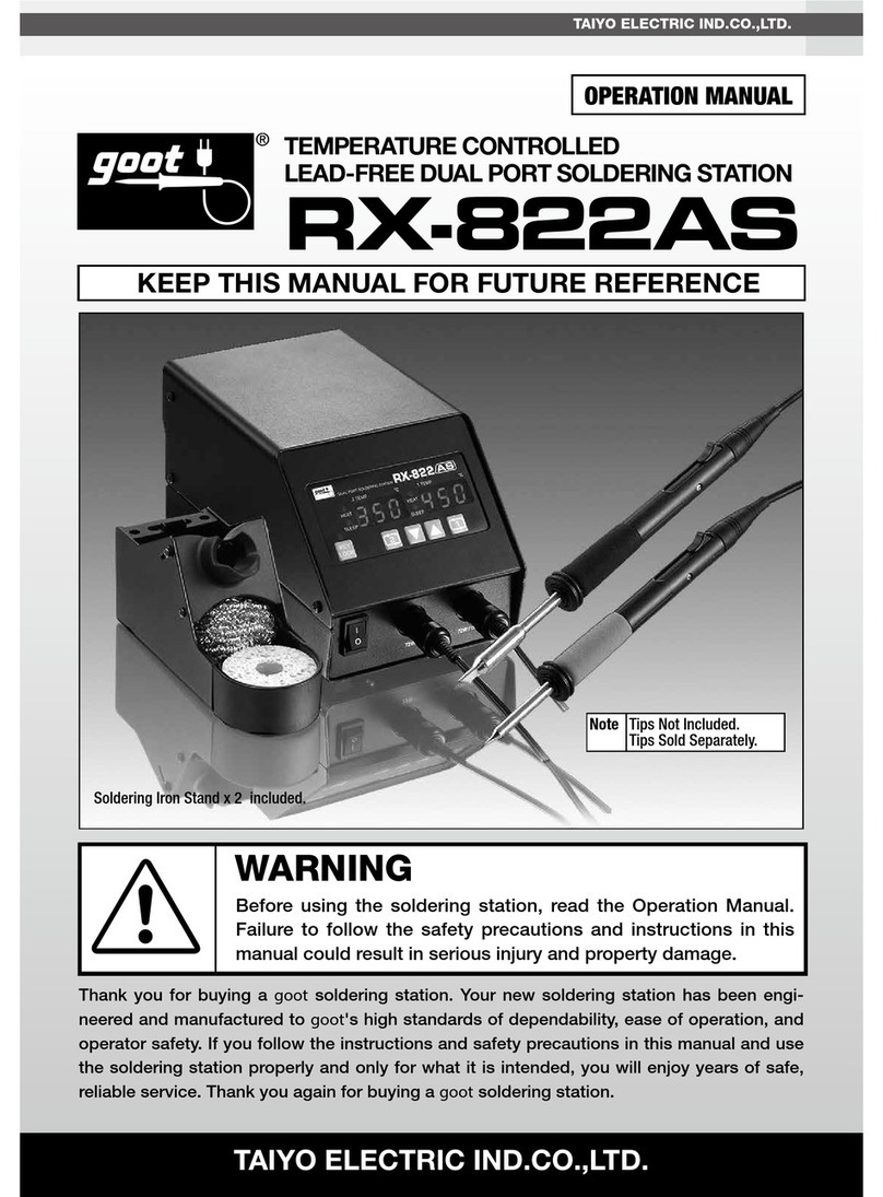
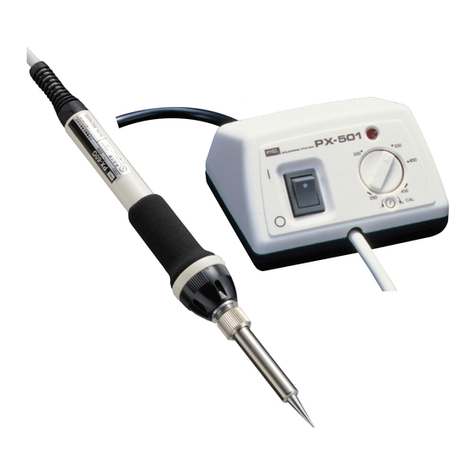
Goot NC-100R User manual

太洋電機産業株式会社
N2ステーション /N2 Station
NC-100R
この度は ステーション NC-100R をお買いあげいただきましてありがとうございます。
本器は の高い品質管理のもとで、安全に使用できるよう設計、製造されています。本器を
安全・快適にご使用いただくため、説明書の注意事項に従って正しくご使用ください。
取扱説明書
警 告
本器をご使用になる前に本取扱説明書を必ずお読み下さい。
警告、使用方法に記述されている内容に従わないと、けが、やけど、
事故などが発生する場合があります。
See English version from P.9
この説明書はなくさないように大切に保管してください。

2
1 はじめに
3 梱包明細
2 仕様
本器は外部からの圧縮空気を供給することで N₂ガスを発生させ、その出力をコン
トロールできる N₂ス テ ー シ ョ ン で す 。N ₂ガスの発生には分離膜を使用し、非常に
省スペースとなっている為、設置場所を選びません。又、RX-802ASPHと組み合
わ せ て 使 用 で き る よ う 、設 計 さ れ て い ま す 。
型番 NC-100R
入 力 空 気 圧 0.3 ~ 0.7MPa
入力空気温度 5℃~ 50℃
N2 ガス発生濃度 99.5% 以上 [0.7MPa,0.5L/min]
推奨 N2ガス発生流量 1.0L/min
フローメー ター 0.5 - 4.0 L/min
最 高 使 用 環 境 温 度 60℃
サイズ 1 8 5 ( L ) × 1 1 8 ( W ) × 1 1 2 ( H ) ( 突 起 部 含 ま ず )
重量 約 2Kg
N2 STATION
NC-100R
ON OFF
1.5
2.5
2.0
1.0
0.5
3.0
3.5
4.0
L/min
0
N2 OUT
+
N2 STATION
NC-100R
ON OFF
1.5
2.5
2.0
1.0
0.5
3.0
3.5
4.0
L/min
0
N2 OUT
+
N2 STATION
NC-100R
ON OFF
1.5
2.5
2.0
1.0
0.5
3.0
3.5
4.0
L/min
0
N2 OUT
+
1. N2 ステーション 2. 帯電防止ポリウレタンチューブ
外 径 φ 6 m m ( 2 m )
3. 取扱説明書(本紙)

3
4 ご使用上の注意
4-1 ご使用上の注意
警 告
本器から排出されるN2ガ ス は 、酸 欠 の 危 険 性 が あ り 、又 本 器
周辺からは高濃度の酸素ガスが排出されますので、使用する
際はかならず換気を行ってください。又、周囲に火気や可燃物
を近づけないでください。
1. 長時間使用しないとき
10分以上使用しないときは本器のN2ガス排出バルブ(4.2 節参照)をOFFに
して圧 縮 空 気 の入 力 を止めてください 。
2. 使用する圧縮空気について
必ずフィルター類で清浄化した圧縮空気を使用してください。
水分相対湿度80%以下
油 分 0.01mg/m3以下
埃0.01 μ m以下
RX-802ASPH 0.5 ~ 1.5[L/min]
供給空気圧 0.7MPa 時 N2濃度 [% ] 99.9 99.7 99.2 98.3
N2流量 [L/min] 0.5 1.0 1.5 2.0
使用する圧縮空気の要求事項
適切な流量範囲
N
2 濃度と流量の関係(代表値)
RX-802ASPHではこて先先端に内蔵されたセンサーで温度制御しております
ので、適切な範囲内の流量ではこて先温度はほとんど変わりません。
3. N2 ガス濃度と流量の関係
4. N2 の流量は適切な範囲内に設定してください。
測定結果の一例
但し、上記範囲以上の流量で 使用すると、こて先温 度が設定温度よりも低くなっ
たり、フラックスやはんだが吹き飛んだりすることがあります。

4
4-2 各部の名称
NC-100R
SER NO
AIR IN
MAX. 0.7MPA
正面側
背面側
N2ガス排出口
適 合 チューブ
外 径φ4mm
N2ガス
フローメーター
測定 流 量レンジ
0.5-4.0L/min
N2ガス
流量調整ツマミ
左回し (+方 向 ):増 加
右回し (−方 向 ):減 少
N2ガス排出
バルブ
左に回す:O N
右に回す:O F F
※ツマミは 必ず 左 右
ど ちら か に 回しきって
下さい 。
銘板シール 圧縮空気入力口
(最大0.7MPa)
適 合 チューブ
外 径φ6mm

5
警 告
注 意
注 意
備 考
本器から排出されるN2ガスは酸欠の危険性がありますので
本器はかならず風通しのよい、換気可能な場所へ設置してく
ださい。
本器周辺には高濃度の酸素ガスが排出されますので、火気や
可 燃 物 から離して 設 置してください 。
本器に供給する空気の最高入力圧は 0.7MPa(7kgf/c㎡)以
下です。0.7M P aよりも大きな入力圧を加えると、チューブ外
れや破裂などが発生する場合があります。
コンプレッサーからの圧縮空気には水分、油分、ほこり等が混
入している可能性がありますので、必ずフィルター類を使用し
て本器にそれらが入らないようにしてください。
そ れ ら が 本 器 に 入 り 込 む と 、得 ら れ る N 2 濃 度 が 低 下 し て し
まいますのでご注 意ください 。
次 ペ ー ジ の「 N C - 1 0 0 R 設 置 例 」の よ う に 必 ず フ ィ ル タ 類 、レ
ギュレータを使 用して下さい 。
尚、新規に配管する場合は一度圧縮空気を勢いよく噴出さ
せ、工場配管内にごみや水分が蓄積されていないか確認して
ください。
特に長い間使用していなかった工場配管には赤錆びや水分
がたまっていることがありますのでご注意ください。
5 設置方法

6
5-1 NC-100R 設置例
6
RX-802ASPH
お客様でご用意願います
こて部 付属のチューブで
直接接続可能です。
鉛フリーはんだ対応
温調はんだこて
圧縮空気入力口へ
コンプレッサ
エアタンク エ アド ラ イヤ
レギュレ ー タ
エ アフィル タ
(ミストセパレータ)
マイク ロ ミ スト
セパレータ
(1M P a 未 満 )
(0.3〜0.7MPa)
NC-100R
N
2
ステ ー ション
(本器) NC-100R 付属の 外 径φ6mm
のチューブをご使 用ください。ワ
ン タ ッ チ で 接 続 可 能 で す 。
システムアップ例
本器は当社の鉛フリー対応ステーション型温調はんだこて
RX-802ASPH との 2 段重ねが可能な設計となっており、
省スペースで 作 業性の良い、鉛フリーはんだ付け 対応シス
テム が 構 築 出 来 ます。

7
5-2 各フィルター類の説明
コンプレッサ
お そらくたいてい の工 場 には 常 備 されてい ると 思いま す。新 規 購 入 され る 場 合 は なる べくオイルレス
のコ ンプ レッ サ ー を 選 択 してくだ さい 。
エアドライヤ
N2 ステーション 内 の N 2ガス分離膜は水分が付着すると性能が低下する性質がありますので、空
気 中の 水 分を除 去する 必 要 が あります。露 点 温 度 + 3 ℃ まで なら許 容 範 囲 です。
エ ア フィル タ
( ミ ス ト セ パ レ ー タ ) 推奨:SMC 株式会社 AF20-01(AFM20-01)
空 気中の大きなごみや高濃 度の油分を取り除きます。次に接 続 するマイクロミストセパレータで も除
去 は 可 能 で す が 、マ イクロ ミ スト セ パ レ ー タ は 比 較 的 小 さ な ご み や 低 濃 度 の 油 分 を 取 り 除くの が 目 的
なので、大きなごみ、高濃度の油分が入ると非常に短時間で目詰まりしてしまいます。
マイクロミ ストセ パ レ ー タ を 守 る 為 の プリフィル タとして 必 要 で す。
マイクロミストセパレータ 推 奨:下 記
前に接続したエアフィルタで取りきれなかった空気中の小さな微粒子や低濃度の油分を取り除きま
す。僅かな微粒子や油分でも N2ガス発生器の中に入り込むと取り除くことはできません。その為、
このマイクロミストセパレータは N 2ステーションを守る重要な役割をしています。
レギュレ ー タ 推 奨:下 記
N2 ステーションの最大入力空気圧は 0.7MPa となっております。このレギュレータは N2ステーショ
ンに入る空気圧を 0.7MPa 以下にします。入力空気圧が 0.7MPa 以下で あれば、このレギュレー
タは 省 略 することもで きます。
マイクロミストセパレータ レギュレータ ( モ ジュラ )
推奨:SMC 株式会社 AWD20-01E 角形埋込式圧力計付き )
レギュレータとマイクロミストセパレータを一 体 化したものです。
注 1)推奨は、全て管接続口径 1/8 になります。

8
6 メンテナンス
7 交換部品
注 意
本 器を分解しないでください。
本器に適正な空気圧が入力されているにもかかわらず、N2ガス
が出ない場合は水分、油分、ほこり等の混入の可能性が ありま
す。その際はお手数ですが修理に出してください。
1.エアドライヤ、エアフィルタ(ミストセパレータ)
マイクロミストセ パレ ータ、レギュレ ータが 機 能して いるか を1ヶ月に1度 点 検して
ください。
2.チューブに傷やガス漏れがないかを 1ヶ月に1 度点検してください。
No. 部品名 品番
①NC 用替ポリウレタンチューブφ 6 × 2m B1072YG00
ご用命は販売店または当社営業部・営業所までお問い合わせください。
注 )本 器 内 部 の N 2ガス分離膜は、交換部品として販売はしておりません。交換が
必要な場合は販売店、もしくは当社営業所に修理に出してください。N2ガス分離
膜 の 交 換 時 期 の目安としましては 、5.1)NC-100R 設置例のような 適 切な使 用状
況下において、流量1.0L/minで1日8時間使用された場合、おおよそ2年間となり
ます。

TAIYO ELECTRIC IND. CO., LTD.
N C -10 0 R
N2STATION
Thank you for buying the NC-10 0R N2Station.
This product has been engineered and manufactured to goot high standards for dependability,
ease of operation, and operator safety. If you follow the instructions and safety precautions in
this manual and on the product, and use the N2Station properly and only for what it is intended,
you will enjoy years of safe, reliable service.
Operation Manual
WARNING
Before using the NC-100R, please read the Operation Manual.
Failure to follow the safety precautions and instructions in this
manual could result in serious injury and property damage.
KEEP THIS MANUAL IN A SAFE PLACE FOR FUTURE REFERENCE

10
1 Outline
3 Unpacking
2 Specifications
This device generates and controls Nitrogen gas. This is achieved
by using an outside source of compressed air. The N C -10 0R uses a
separation membrane to generate Nitrogen. It is designed to be used with
the RX-802ASPH and to be as compact as possible so it can be installed
anywhere.
MODEL NC-100R
Input Air Pressure 0.3–0.7MPa
Input Air Temperature 5˚C–50˚C
Nitrogen Generation Density More than 99.5% [0.7MPa, 0.5L/min]
Recommended Nitrogen Generation Flow Rate 1.0L/min
Flow Meter 0.5 - 4.0 L/min
Max. Environmental Temp. 60˚C
Dimensions 185(L)×118(W)×112(H) (excl. protruding parts)
Weight 2Kg approx.
N2 STATION
NC-100R
ON OFF
1.5
2.5
2.0
1.0
0.5
3.0
3.5
4.0
L/min
0
N2 OUT
+
N2 STATION
NC-100R
ON OFF
1.5
2.5
2.0
1.0
0.5
3.0
3.5
4.0
L/min
0
N2 OUT
+
N2 STATION
NC-100R
ON OFF
1.5
2.5
2.0
1.0
0.5
3.0
3.5
4.0
L/min
0
N2 OUT
+
1. N2 Station 2. Anti-static Polyurethane Tube
Outer diameter 6mm
(2m)
3. Operation Manual

11
4 Precautions
4-1 Precautions
WARNING
The Nitrogen output from this device can cause an
oxygen deficiency in the immediate area. Please make
sure there is appropriate ventilation in place when
using this unit. Highly concentrated oxygen is output
from this device. Do not use near flammable materials.
1. When Not Using for a Long Period of Time
(refer to 4.2) to OFF and stop the input of compressed air.
2.About the compressed air being used
Only use clean compressed air that has been filtered through the various
filters
Moisture Less than 80%relative humidity
Oil Content Less than 0.01mg/m3
Particles Less than 0.01μm
RX-802ASPH 0.5–1.5[L/min]
When the air pressure
supplied is 0.7MPa
Nitrogen Density [%] 99.9 99.7 99.2 98.3
Nitrogen Flow rate [L/min] 0.5 1.0 1.5 2.0
Requirements for the compressed air being used
Recommended flow rate range
Density and flow rate of Nitrogen gas (Representative values)
The temperature is controlled by the sensor inside the tip of the
RX-802ASPH. When the flow rate is set within the appropriate range, the
tip temperature should not fluctuate.
3.The Density and Flow Rate of Nitrogen gas
4. Set the Nitrogen flow rate within the appropriate range
Example measurement results.
However,settingaflowrateabovetheupperrangecancausethe
tiptemperaturetobelowerthanthesettemperature,orcauseflux
orsoldertosplatter.

12
4-2 Name of Parts
NC-100R
SER NO
AIR IN
MAX. 0.7MPA
FRONT
BACK
Nitrogen Output
Appropriatetube
outerdiameter:4mm
Nitrogen Flow Meter
MeasurementRange
0.5-4.0L/min
Nitrogen Flow Regulation
Turn to left: Increase ow
Turn to right: Decrease ow
Nitrogen Output Valve
Turn to left: ON
Turn to right: OFF
*Please turn the knob fully to
the ON or OFF position.
Nameplate Compressed Air Input
Appropriatetubeouter
diameter:6mm

13
WARNING
CAUTION
CAUTION
NOTE
The Nitrogen output from this device can cause an
oxygen deficiency in the immediate area. Please
make sure there is appropriate ventilation in place
when using this unit. Highly concentrated oxygen is
output from this device. Do not use near flammable
materials.
Maximum input air pressure for this device must be
under 0.7MPa (7kgf/cm2). Exceeding 0.7MPa can
cause the tube to disconnect or even explode.
Compressed air supplied by the compressor can
contain water, oil, or dust. Make sure these elements
do not enter the unit by using appropriate filters.
Please note that Nitrogen density will decrease if
these elements enter the device.
Please use a regulator and filter as shown in the
NC-100R Installation Example, on the following page.
Before initial use, please make sure all moisture
and dirt is removed from the shop piping by blowing
compressed air fully through the pipes. Shop piping
that has not been used for a long period is very likely
to contain rust and moisture.
5 Setup

14
5-1 NC-100R Installation Example
6
RX-802ASPH
The following components should be prepared before using the NC-100R
Compressor
Air Tank Air Dryer
Regulator
Air Filter or
(Mist Separator)
Micro Mist
Separator
(Under 1MPa)
(0.3〜0.7MPa)
N C -10 0R
N2 Station
Please use the φ6mm
diameter tube included with
the station. It can be attached
Connect to
Compressed Air
Input (on the back of
the unit)
Temperature Controlled Lead-free
applicable Soldering Station
The tube from the handpiece can be
attached directly to the NC-100R.
Set-Up Example
This unit is designed to be stackable with our
temperature-controlled lead-free soldering station
RX-802ASPH in two layers, allowing you to build a
space-saving and workable lead-free soldering system.

15
5-2 Explanation of the required components
Compressor
Most factories are equipped with a compressor. When purchasing a new one, we recommend
an oilless compressor.
Air Dryer
The Air Dryer removes moisture from the air. The Nitrogen separation membrane inside
the station is adversely affected by moisture. Performance will decrease if moisture is
not removed from the air. A temperature up to +3°C above the dew point temperature is
acceptable.
Air Filter or Mist Separator (Recommended: SMC Corporation AF20-01/
AFM20-01) *
The Air Filter removes large particles or highly concentrated oil droplets from the air. The
Micro Mist Separator also performs this function. However, compared to the Air Filter it only
lters smaller particles and low concentration oil droplets from the air, so it is easily clogged.
The Air Filter could be considered as a pre-lter to protect the Micro Mist Separator.
Micro Mist Separator (Recommended: see below)
The Micro Mist Separator removes the tiny particles and oil droplets in the air that could not
be removed by the Air Filter/Mist Separator. Even minute particles that enter the N2Station
can cause problems. The Micro Mist Separator plays an important role in protecting the N2
Station.
Regulator (Recommended: see below)
The maximum input air pressure is 0.7MPa. The Regulator controls the air pressure going into
the N2Station so that it is under 0.7MPa. If the input air pressure is already less than 0.7MPa,
then the Regulator is not required. However, to protect the NC-10 0R
from sudden air pressure surges we strongly recommend installing the
Regulator.
Micro Mist Separator Regulator (Modular)
(Recommended: AWD20-01E, Square embedded type pressure
gauge attached)
This is made up of a Regulator and a Micro Mist Separator.
Micro Mist Separator and Regulator may be purchased separately, or
you may purchase the combined modular unit.
* For connections, a 1/8 standard is recommended.

16
6 Maintenance
7 Replacement Parts
Caution
Do not dismantle this product.
Even when the correct air pressure has been input, if
Nitrogen is not being output, it could be due to moisture,
oil or dust clogging the unit up. If this occurs, please
have the unit serviced.
1. At least once a month, please check the Air Dryer, Air Filter/Mist
Separator, Micro Mist Separator and Regulator are working properly.
2. Please also check the tubing once a month to ensure there is no damage
and that air and/or gas is not leaking from the tube.
No. Part Name Part Code
①Replacement NC Polyurethane tube φ6×2m B1072YG00
Please contact your nearest distributor.
NOTE: The Nitrogen Gas Separation Membrane inside this device is not
available as a replacement part. Please return the unit to your distributor to
have this repaired. At the following level of usage, the Nitrogen Separation
Membrane should be replaced after two years: Appropriate installation, as
shown in section 5.1, in use for 8 hours per day with a flow rate of 1.0L/min.
TAIYO ELECTRIC IND.CO.,LTD.
www.goot.co.jp E-mail:info@goot.co.jp
2-16-8 Yamate Fukuyama Hiroshima 720-0092, JAPAN
TEL:(81)84-951-1512 FAX:(81)84-951-9531
Customer service : Contact your nearest distributor
TAIYO ELECTRIC IND.CO.,LTD.
太洋電機産業株式会社
is a registered trade mark of TAIYO ELECTRIC IND. CO., LTD.
Printed in Japan, MARCH 2020 A1070NJ00
お客様相談窓口
Home Page:
www.goot.co.jp
E-mail:
東京03(3832)1774 大阪06(6644)3508
新潟0256(47)1715 広島084(951)9010
Table of contents
Other Goot Soldering Gun manuals