aoyue INT 738 User manual

24
PartNo. Description
10094 Hotairgunheatingelement
30105S Plastichandleofhotairgun
S012 Hotairguncompletehandle
20962 Hotairgunmetalpipe
P005 DiaphragmPump
C001 SolderingIronheatingelement
3098S Plastichandleofsolderingiron
B004 SolderingIroncompletehandle
201701 SolderingIronTipenclosure
SPAREPARTSLIST
Manufacturer:
AOYUETONGYIINTERNATIONALLIMITED
JishuiIndustrialZone,Nantou,ZhongshanCity,
GuangdongProvince,P.R.China
http://www.aoyue.com
Professional Repairing System
INSTRUCTION MANUAL
ThankyouforpurchasingAoyueInt738ProfessionalRepairingSystem.
Itisimportanttoreadthemanualbeforeusingtheequipment.
Pleasekeepmanualinaccessibleplaceforfuturereference.
I
INT
NT 738
738

2
This manual is designed to familiarize the technician with
the proper operation and maintenance of the
equipment. The “Care and Safety Precautions” section
explains the hazards of using any type of soldering or
reworking device. Please read carefully and observe the
guidelines in order to maximize usage and minimize the
risk of injury or accidents .
23
AIRNOZZLES
Note:Theaboveitemsaresoldseparately.

22
Note:Theaboveitemsaresoldseparately.
REPLACEMENTTIPS
3
TABLE OF CONTENTS
Product Description ……………………………………… 4
Package Inclusion ………………………………..…..… 5
Spare Parts List .…..……………………..…….………… 5
Specifications ……………………………..……………. 6
Functions & Features ……………………….………….. 7
Safety Precautions ……….……………………….……... 7
Operating Guidelines
Control Panel ………………………………………. 8
Assembly and Preparation ……………………….. 9
Startup procedures ………………………………. 10
Hot Air Gun …………….………………...………… 11
Soldering Iron ………………………………..……. 15
DC Power Supply …..………………………..……. 16
Maintenance ……………….………………………..…. 16
Basic troubleshooting guide ……………………………. 20
Replacement Solder Iron Tips ……………………….… 22
Replacement Air Nozzles ...………………………..….… 23

4
PRODUCTDESCRIPTION
The Aoyue INT738 Professional Repairing System is a reworking
equipment that combines the functionality of a Hot Air Gun, Soldering
Iron,andSmokeabsorberinonesophisticatedpackage.
Oneofthenotablefeaturesofthisdeviceistheautocoolingprocess
of the Hot Air Gun. This functionality protects the device (and its
components) from excessive heat by blowing air (at room temperature)
uponachievinganyofthefollowingtwoconditions:(1)whenthesoldering
gunremainedidleonitsrestinghandleafteracertainperiodand(2)when
thetemperatureofthedeviceisaboveasafethresholduponturningoff.
Thiswillbediscussedinfurtherdetailtogetherwiththecompletefeatures
inthesucceedingsectionsofthismanual.
Finally, the unique, innovative design with digital control panel and
displayprovidesprecision,safety,andeaseofusetomatchallreworking
requirements.
21
PROBLEM6: AIR PRESSURELEVELISSIGNIFICANTLYLOWNO
MATTERHOWHIGHTHEAIRFLOWLEVELISCALIBRATED
Case1:Checkthemainsvoltage(ACpowersource).Ifthevoltagelevel
fallssignificantlylow,about1520%lowerthanthestandard,therewill
alsobeanoticeabledropintheairpressurelevel.
SOLUTION:Pleaserefertoyourlocalpowerserviceprovider.
Case 2: The microcontroller might have detected the operating
frequency incorrectly. The user will notice that airflow level is weaker
withreferencetotheairflowgaugecomparedwiththedisplayedvalue.
SOLUTION: Try to press the RESET button on the panel to let the
deviceredetecttheproperoperatingfrequency.
PROBLEM 7: SOLDERING IRON TEMPERATURE DISPLAY PANEL
SHOWS“PLUG”CHARACTERS
Case1:Thesystemshows“
PLUG
”fromthesolderingirontemperature
displaypanel.
SOLUTION1: Check if the soldering iron connection assembly is
properlyconnectedandsecuredtothereceptacleonthecontrolpanel.
SOLUTION2: Make sure the soldering iron tip is properly inserted
andsecuredinsidethehandle.Losecontactsbetweenthetipandhandle
canalsocausethiserrormessage.
PROBLEM8:DISPLAYANDOTHERDEVICEOPERATIONISSUES
SOLUTION: TrytoswitchOFFthedeviceandswitchONagain.Unplug
the system from the main power source and plug in again when
necessary
OTHERPROBLEMSNOTMENTIONED:
Contactthevendor.
BASICTROUBLESHOOTINGGUIDE

20
PROBLEM1:THEUNITHASNOPOWER
1. CheckiftheunitisswitchedON.
2. Checkthefuse.Replacewiththesametypeiffuseisblown.
3. Checkthepowercordandmakesuretherearenodisconnections.
4. Verifythattheunitisproperlyconnectedtothepowersource.
PROBLEM2:TEMPERATUREDISPLAYISALWAYSABOVE500
o
C
Description: Constant display of above 500
o
C temperature from the
panelthendisplaysablinking“OFF”onthepanelafterafewminutes.
SOLUTION:
Thethermalsensormaybebrokenandneedstobereplaced.
PROBLEM3:ACTUALAIRTEMPERATUREISNOTINCREASING
Description:Actualtemperaturereadingisnotincreasingordecreasing
based on desired level. The panelwill then display a blinking“OFF” on
panel.
SOLUTION:
Theheatingelementmaybebrokenandneedstobereplaced.
PROBLEM4:THEUNITISVIBRATINGTOOMUCH
Checkifthe4screwsthatholdthepumpinplaceareproperlyandtightly
connected. Unplug the system from the main power source before
openingthecasetochecktheinternalsettings.
PROBLEM5:THEUNITISVERYNOISY
SOLUTION: Makesurethescrewatthecenterofthebaseofthemain
unit has been removed. This holds the pump in place during
transportationandneedstoberemovedbeforeusingtheequipment.
BASICTROUBLESHOOTINGGUIDE
5
PACKAGEINCLUSION
SolderingIronwith
SmokeAbsorber
30181XFilterPads
(6pcs.)
PowerCord
939Vacuum
SuctionPen
2630BSolderingIronHolder
withSolderWireStand
HotAirGunand
HotAirGunHolder
AirNozzles
(1124,1130,
1197,1010, 1313,
738MainStation
SolderingIron
SpareHeatingElement
G001ICPopper

6
SPECIFICATIONS
MAINSTATION
PowerInput: availablein110V/220V
StationDimensions: 188(w)x126(h)x250(d)mm
Weight: 6.3Kg
SOLDERINGIRON
PowerConsumption: 45W
TemperatureRange: 200°C480°C
HeatingElement: CeramicHeater
OutputVoltage: 24V
HOTAIRGUN
PowerConsumption: 550W
TemperatureRange: 100°C480°C
HeatingElement MetalHeatingCore
Pump/MotorType: DiaphragmPump
AirCapacity: 23l/min(max)
19
●SoldertheotherREDwireofheatingelementwithYELLOWwireon
PCB.
●SolderBLUEwireofheatingelementwithBLUEwireonPCB.
●SolderWHITEwireofheatingelementtowithBLACKwireonPCB
The5pinSolderIronsocketcanbetestedtodetectfaultsinthe
handpiece:
Beforeplugginginthehandpiececonductthefollowingtest:
If any of the above mentioned combination registers a short review the
stepsinreplacingtheheatingelementtoensureproperconnections.
CAREandMAINTENANCE
Pins4&2 ∞
Pins4&1 ∞
Pins5&1 ∞
Pins5&2 ∞
Warning:Ensurenoneoftheabovementionedconditionsare
presentbeforeplugginginthehandpiece.Failuretodosocan
damagetheinternalcircuitryoftheunit.
Testtheresistancesofthefollowingconfigurations:
If resistance test conforms to the above tables then the soldering iron
hand piece is deemed working and can be plugged in to the Soldering
Iron receptacle for usage, if problems after installation of new heating
elementoccursreviewthepreviousstepstodoublecheckconnections.
Note:resistancevalueofsensor(Pins4&5)mayvaryaccordingtoambient
temperature
Pins1&2 19to23 Ω
Pins4&5 1.2to3Ω
Pin3&soldertip Below2 Ω

18
To test if the heating element of the soldering iron is in working
condition:
Let whole assembly cool down to room temperature and unplug from
electricalsourcesbeforecontinuingthetestsbelow:
1. Followdisassemblingthehandpieceguide.
2. DothefollowingtestsonthehandpiecePCBboard:
Resistancevalueofheatingelement(RED)1923Ω
Resistancevalueofsensor(blue)1.2—3Ω
Note:resistancevalueofsensormayvaryaccordingtoambient
temperature
Aftertestingcheckresultswiththefollowing:
●If the resistance value is not as stated above replace the heating
element.
●Ifa0Ωorinfiniteresistancesaremeasuredcheckforshortsoropen
circuits.
●Itermittent readings can also be caused by cold solder double check
solderpointsiftheheatingelementhasrecentlybeenreplaced.
Theheatingelementcanbereplacedasfollows:
1. Followthestepsin“disassemblingthesolderingiron”.
2. Unsoldertheheatingelementwires(RED)andthesensorwires(blue).
3. The old heating element can now be detached from the hand piece
board.
4. Detachthemetal protectorlocatedat thebottom partof theheating
element.
5. Reattach the metal protector to the bottom part of the new heating
element.
6. PasstheNewheatingelementswires(RED)thrutheholeslocatedon
topoftheboard.
7. Soldertheheatingelement’swiresandthesensorwirestotheboard
8. SolderoneREDwireofheatingelementwithREDwireonPCB.
CAREandMAINTENANCE
7
CAUTION:Improperusagecancauseseriousinjurytopersonnel
and/orextensivedamagetoequipmentandworkingarea.Foryour
ownsafety,pleaseobservethefollowingprecautions.
●MicroprocessordrivenESDsafeequipment.
●3in1repairingsystemcombiningHotAirGun,SolderingIron,
andSmokeabsorberinonesophisticatedpackage.
●Digital control and display of hot air temperature, soldering
irontemperatureandairpressure,.
●Programmabletimer functionality from 6 to 9999 seconds for
automatingreworkingtasks.
●Userconfigurable 1 to 20minute idletoautostandby mode
(with5minutesasdefault)foradditionaldeviceprotectionand
powersaving.
●Builtin autocooling process that protects the systemand its
components from excessive heat, thereby, prolonging usage
life.
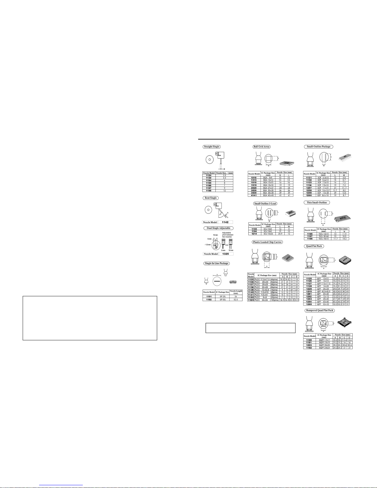
●Compatibilitywithvarioustypeofairnozzlesandsolderingiron
tips.(PleaserefertoMISCELLANEOUSsectionofthismanual.)
FUNCTIONSandFEATURES
●Check each component after opening the package to make
sureeverythingisingoodcondition.Ifthereareanysuspected
damage, don’t use the item and report the issue to your
dealer.
●Turn off power switch and unplug the unit from the mains
power source when moving the equipment fromone location
toanother.
●Donotstrikeorsubjecttheequipment(oritscomponents)to
physicalshock.Usecarefullytopreventdamageonanyparts.
●Makesuretheunitisalwaysgrounded.Alwaysconnectpower
toagroundedreceptacle.
SAFETYPRECAUTIONS

8
CONTROLPANELGUIDE
LEGEND:
1—AirGauge
2—HotAirGunTemperatureControlButtons
3—AirPressureControlButtons
4—AutoReworkTimeAdjustmentButtons
5—SolderingIronTemperatureControlButtons
6—HotAirOutputTerminal
7—Smokeabsorberconnector
8—SolderingIron5PinConnectingTerminal
9—Mainpowerswitch
10—Functionselector
11—HotAirGunTemperatureDisplay
12—HotAirGunPressureDisplay
13—AutoReworkTimeDisplay
14—SolderingIronTemperatureDisplay
15—HotAirGunActivationSwitch
16—AutoReworkingActivationSwitch
17—Reset
18—SolderingIronActivationSwitch
19—Vacuumindicator
738
Power
Vacuum
Smoke
absorber
SMD
REWORK
15
16
17
18
19
17
STEPSinChecking,CleaningandTinningtheTip
1. Settemperatureto250°C(482°F)
2. After real temperature reaches the set temperature, use a damp
spongetocleanthetipandcheckfordamages.
3. If the tip has oxidation, apply solder and wipe using the damp
sponge,repeatthesestepsuntiloxidationisremoved.
4. After cleaning, coat tip with a thin layer of solder and set it aside
readyforthenextusage.
5. Ifthetipshowsdisfigurationorhasrustonit.Changethetip.
The hand piece may be disassembled for trouble shooting and
repair:
1. Turnofmainstationandunplugfrompowersource.
2. Detach the soldering iron plug(”15” as shown in thefigure below)
fromthemainunit.
3. Turnthenut,(“1”asshowninthefigurebelow)counterclockwise.
4. Pulloutthetipenclosure(“2”asshowninthefigurebelow),thetip
(“3”asshowninthefigurebelow),andthetipstand(“4”asshown
inthefigurebelow).
5. Turnthefrontmodule(“5” asshowninthefigurebelow)counter
clockwisetoreleaseitfromthemainbody.
6. PushouttheHeatingelement(“6”asshowninthefigurebelow)via
thecord(“14”asshowninthefigurebelow).
CAREandMAINTENANCE

16
A. ReplacingtheHotAirGunheatingelement
1. Removethescrewswhichsecurethehandle andslide thecord
tube.
2. Open the handle. Disconnect the ground wire and remove the
pipe.
3. Removetheheatingelementbydisconnectingtheterminal.
4. Insertanewheatingelementandreconnecttheterminal.Handle
theheatingelementwithcare.Neverrubitswire.Reconnect
thegroundwireafterreplacingtheelement.
5. Assemblethehandleinthereverseorderofdisassembly.
B. CarefortheSolderingIrontip.
Alwayskeep thesolderplatedsectionof thetipcoatedwith asmall
amountofsolder.Ifthetipiscoatedwithoxide,thetip’sheatconductivity
will be lowered. Coating the tip with a small amount of fresh solder
ensuresmaximumheatconductivity.
OPERATINGPROCEDURE
E..SMOKEABSORBER
1. Wait until the soldering iron reaches the set temperature and
stabilizes.
2. SetVacuumControlto
smokeabsorber
.
3. CheckiftheVacuumIndicatorlightsup.
4. Fumesabsorbedwillpassthroughafilterandbeblownoutthruthe
hot air gun. So the smoke that is blown out from the hot air gun
duringsolderingisalreadyfiltered.
IMPORTANT: Filters should be cleaned and replaced
regularlysothatitwouldnotclogup theair pathand will
effectivelycleanthetoxicfumesproducedduringsoldering
process.
CAREandMAINTENANCE
9
A. SolderingIron
1.InstallthesolderwiretothesolderingironholderasinFigure2.
2. Connect the soldering iron cord assembly to the 5pin output
terminalfoundatthelowerportionofthemainunit.Pleasereferto
item8fromtheControlPanelGuide.
3.Placesolderingirontothesolderingironstandasshownabove.
B.HotAirGun
TheHotAirGunholderwasinstalledonthestationupsidedown
forpackagingpurpose.TosetuptheHotAirGunholder:
1. Loosenthetwoscrewsthatsecuretheholdertothestation.
2. Turntheholderrightupside.
3. Fastenthetwoscrewsback.
4. Placethehotairgunontheholderinpreparationforusage.
Note:Makesurethescrewatthecenterofthebaseofthemainunit
hasbeenremoved.Thisholdsthepumpinplaceduringtransportation
andneedstoberemovedbeforeusingtheequipment.
C.SmokeAbsorber
Attachthesmokeabsorbingtubetothevacuumcap.Makesurethat
thecordconnectionsarefreefromanytangles.
Figure2.Solderingironstandwithsolderwireholder
ASSEMBLYandPREPARATION

10
OPERATINGGUIDELINES
IMPORTANTREMINDERS:
1. Makesuretheequipmentisplacedonaflatstablesurfaceand
all its heatgenerating components placed on their respective
holders/stands.
2. EnsureallswitchesareOFFpriortoreworking.
3. Ensureallterminalconnectionsareproperlysecured.
A.STARTUPPROCEDURE
1. Plugthedevicetothemainpowersource.
2. SwitchONthedeviceusingthemainpowerswitch(item9onthe
CONTROLPANELGUIDE)foundatthelowerrightportionofthe
controlpanel.
3. Thedisplaypanelwillshowtheproductnamemomentarilyandthen
“OFF”oneachlineofthepanel,providedallfunctionswitchesare
deactivated.Seebelowforillustration.
4. Theairgauge(item1)willalsoappearilluminatedbyamplelightand
themetalballinsideisatthelowestpositionofthevisiblearea.
5. Thesystemwillremaininthisstateuntilafunctionisactivated.
NOTE:PleaserefertotheCONTROLPANELGUIDEifneeded.
15
C.AUTOMATEHOTAIRREWORKING
1. Turnonthehotairgunfunctionswitch,andsettothedesired
reworkingtemperature.Turnofhotairgunfunctionswitch.
2. Turnontheautomatefunctionswitch,”16”fromthepanel,Setthe
timebyusingtheup/downreworktimebutton,”4”fromthepanel.
Itispresetat300seconds.
3. Afterpreferredautomatereworktimehasbeenset.Turnonthehot
airgunfunctionswitch.
4. Timerwouldstartcountingdownwhentheactualhotair
temperaturehasreachedthesettemperature.Onceautomate
reworktimeisfinished,itwouldcooldownautomatically,and
displaytheletters“End”indicatingautomateprocessisfinished.
5. Toresumemanualhotairreworkingdepressautomatefunction
switch.
D.SOLDERINGIRON
1. CheckiftheSolderingIronisattachedproperlytothe6pin
receptacleandthevacuumtubeissecurelyconnected.
2. TurnonthePowerSwitch.
3. PresstheSolderingIronfunctionswitchtoturnonsolderingiron.
“18”fromthepanel.
4. Whenthedisplayshowstheword“PLUG”checktheconnectionof
thesolderingirontoitsreceptacle.
5. TheSolderironissettoautomaticallyincreasetemperatureto249°
Cuponturningon.Itwillshowthesettemperaturewhenyouare
adjustingthetemperature,thenitwillautomaticallyswitchto
displaytheactualtemperaturewhenyouhavefinishedsettingthe
temperature.
5. Setthetemperatureusingtheup/downSolderironbuttons,”5”
fromthepanel
6. Startusingwhenrealtemperaturereachesthesettemperature.
OPERATINGGUIDELINES

14
OPERATINGGUIDELINES
Autosleep mode — unit is also programmed to have an autosleep
mode,thisisactivatedwhenhotairgunisturnedonbutisplacedonthe
hot air gun holder and not put to use for set amount of minutes,
temperatureautomatically decreases and eventually turns to sleep mode.
When the handle is held up again the unit will go back to its previous
setting.
SleepModeTimerSetUp
1. SwitchtheunitON(orpress“Reset”button,fromthepanel).
2. Press and hold hot air gun up button, while the Name and model is
displayed.
3. Display panel, will initially indicate ‘05’, which means the device will
switchto sleep modeafter 5 minutes(default)ofidle timeandifthe
nozzleisdockedonthehandleforthedurationoftime.
4. Adjust the time before sleep by pressing air pressure up and down
buttons.
5. PressHotairgundownbuttontoconfirm.
6. Thedevicewillstartcountingdownwhenthehotairgunisdockedon
thehandle.Oncecountdownisfinishedandthehotairgunstilldocked,
the device will automatically blow air (at room temperature) to bring
downtemperatureto90
o
C.Thepanelwillthendisplayfourdashes“
“toindicatethatthedeviceisnowinsleepmode.
NOTES:
●Timeisconfigurablefrom1to20minutes(default5minutes).
●Thedevicehasaswitchlocatedatthehandle(cradle),whichactivates
thecountdownbeforethesystemgoestosleep.
●Oncethehotairgunisreleasedfromthehandleduringsleepmode,
the unit will automatically switch back to previous working
temperatureandairflowlevelparameters.
●Timer settings defaults back to 5 minutes every time the unit is
powereddownortheresetbuttonispushed.
11
OPERATINGGUIDELINES
B.HOTAIRGUN
1. SwitchONtheequipmentbyactivatingmainpowerswitch(9).
2. ActivateHOTAIRGUN functionswitch(15)fromtherightsideofthe
controlpanel.
3. The system will immediately blow air from the hot air gun while
graduallyincreasingthe airtemperatureto thedefaultvalue of99°C.
Theballinsidetheairgaugewillalsosettlesomewhereinthemiddleof
the visible area, corresponding to an air pressure level of 50. The
display area for hot air temperature and air pressure level, items 11
and 12, respectively, will show the
following.
4. AdjustairpressureusingtheAIRPRESSUREcontrolbuttons(3).
5. AdjusthotairtemperatureusingtheHOTAIRGUNtemperaturecontrol
buttons(2).Note:Whenincreasingordecreasingtheairtemperature,
the prefix of the display area for hot air gun temperature (11) will
temporarily change from uppercase “H” to lowercase “h”, indicating
that heat is being adjusted. Once the buttons are released, it will
switch back to its original case while the temperature value also
gradually increases or decreases and until the desired temperature is
reached.

12
OPERATINGGUIDELINES
6. Youmaystartreworkingassoonasthedesiredairtemperatureand
airpressurelevelsarereached.
7. . When reworking is complete, place the Hot Air Gun back to its
holder.
8. DeactivatetheHOTAIRGUNfunctionswitch(15).Thesystemwill
immediatelystarttheautocoolingprocess.
Note:Duringthisprocess,thesystemwilltrytoreleaseexcessheatby
blowingair(atroomtemperature)untilitreachesasafe temperature
valueof85°CbeforecompletelyswitchingOFF.
9. WaitfortheautocoolingprocesstofinishbeforeswitchingOFFthe
main power switch (9).If the display panel shows “OFF” on each
line,thenitisnowsafetodoso.
10. Unplugthedevicefromthemainpowersource.
IMPORTANT:Remembertosetairflowlevelfirstbeforesettingthe
temperaturesothatitwouldnotdamagetheheatingelement,causingittobe
burntoutprematurely.Thiswouldhelplengthentheusagelifespanof the
mainunitandtheheatingelement.
IMPORTANT:Airflowlevelshouldbesetaccordingly,workingwithlow
airflowandhightemperatureoftencausesheatingelementtogeteasilyburnt.
13
OPERATINGGUIDELINES
Autocoolofffunction
1. When reworking is complete, return the Hot Air Gun to its holder
andDO NOTimmediatelyunplugthedevicefromthemainpower
source.
2. Deactivate the HOT AIR GUN activation switch first in order to
activatetheautocoolingprocess.Thesystemwillstarttoblowair
(at room temperature) at maximum rate to reduce heat from the
hotairgunandbringthetemperaturedowntoasafelevelof90°C.
Duringthis time, theprefixof hotair gun temperature display will
also change from “H” to “C” while temperature is gradually
decreasing. The air pressure level, likewise, will be at its highest
readingas indicatedfromthedisplay panel.Oncethetemperature
dropstoapproximately90°Cthehotairgunwillautomaticallystop
anddisplay“OFF”onthepanel.Itisnowsafetounplugthedevice
fromthemainpowersourceifthesystemreachedthisstage.
3. Unplugthedevicefromthemainpowersource.
4. Allow the device (and its components) to completely cool down
before keeping in a safe and dry place. (Optional but
recommended).
Table of contents
Other aoyue Soldering Gun manuals