Weller WSD 151 User manual

EN FR IT ES PT NL SV DK FI GR TR CZ PL HU SK SL EE LV LT DE
WSD 151 / PUD 151R
Betriebsanleitung

WSD 151 / PUD 151R
WSD 151 / PUD 151R
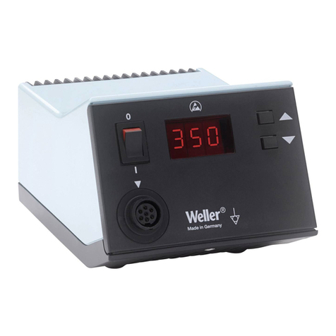
Geräteübersicht
1 Netzschalter
2 Digitalanzeige (Display)
3 UP-Taste
4 DOWN-Taste
5 Optische Regelkontrolle
6 Potentialausgleichsbuchse
7 Anschlussbuchse für Lötkolben
8 Netzanschluss
9 Netzsicherung
10 Spannungswahlschalter
(umschaltbar 230 V/120 V)
(PUD 151R)
11 Typenschild
12 Potentialfreier Kontakt
(nur PUD 151R)
13 Stecker für potentialfreien
Kontakt (PUD 151R)

WSD 151 / PUD 151R 3-10
DE EN FR IT ES PT NL SV DK FI GR TR CZ PL HU SK SL EE LV LT
Inhalt
1Zu dieser Anleitung .................................................................... 3
2Zu Ihrer Sicherheit ..................................................................... 3
3Lieferumfang .............................................................................. 4
4Gerätebeschreibung .................................................................. 4
5Gerät in Betrieb nehmen ............................................................ 7
6Gerät bedienen .......................................................................... 7
7WSD 151 / PUD 151R pflegen und warten ................................ 9
8Fehlermeldungen und Fehlerbehebung..................................... 10
9Zubehör ..................................................................................... 10
10Entsorgung ................................................................................ 10
11Garantie ..................................................................................... 10
1Zu dieser Anleitung
Wir danken Ihnen für das mit dem Kauf der Weller WSD 151 /
PUD 151R erwiesene Vertrauen. Bei der Fertigung wurden strengste
Qualitätsanforderungen zugrunde gelegt, die eine einwandfreie
Funktion des Gerätes sicherstellen.
Diese Anleitung enthält wichtige Informationen, um die Lötstation
WSD 151 / PUD 151R sicher und sachgerecht in Betrieb zu
nehmen, zu bedienen, zu warten und einfache Störungen selbst zu
beseitigen.
ZLesen Sie diese Anleitung und die beiliegenden
Sicherheitshinweise vor Inbetriebnahme des Gerätes vollständig,
bevor Sie mit der Lötstation WSD 151 / PUD 151R arbeiten.
ZBewahren Sie diese Anleitung so auf, dass sie für alle Benutzer
zugänglich ist.
1.1 Berücksichtigte Richtlinien
Die mikroprozessorgeregelte Weller Lötstation WSD 151 /
PUD 151R entspricht den Angaben der EG Konformitätserklärung
mit den Richtlinien 2004/108/EG und 2006/95/EG.
1.2 Mitgeltende Dokumente
−Betriebsanleitung der Lötstation WSD 151 / PUD 151R
−Begleitheft Sicherheitshinweise zu dieser Anleitung
2Zu Ihrer Sicherheit
Die Lötstation WSD 151 / PUD 151R wurde entsprechend dem
heutigen Stand der Technik und den anerkannten
sicherheitstechnischen Regeln hergestellt. Trotzdem besteht die
Gefahr von Personen- und Sachschäden, wenn Sie die
Sicherheitshinweise im beiliegenden Sicherheitsheft sowie die

4-10 WSD 151 / PUD 151R
Warnhinweise in dieser Anleitung nicht beachten.
Geben Sie die Lötstation WSD 151 / PUD 151R an Dritte stets
zusammen mit der Bedienungsanleitung weiter.
2.1 Bestimmungsgemäßer Gebrauch
Verwenden Sie die Lötstation WSD 151 / PUD 151R ausschließlich
gemäß dem in der Betriebsanleitung angegebenen Zweck zum
Löten und Entlöten unter den hier angegebenen Bedingungen.
Der bestimmungsgemäße Gebrauch der Lötstation
WSD 151 / PUD 151R schließt auch ein, dass
−Sie diese Anleitung beachten,
−Sie alle weiteren Begleitunterlagen beachten,
−Sie die nationalen Unfallverhütungsvorschriften am Einsatzort
beachten.
Für andere von der Betriebsanleitung abweichende Verwendung
sowie bei eigenmächtig vorgenommenen Veränderungen am Gerät
wird vom Hersteller keine Haftung übernommen.
3Lieferumfang
−Lötstation WSD 151 T005 32 766 99
−Lötstation PUD 151R T005 32 786 70
−Netzkabel
−Klinkenstecker
−Betriebsanleitung WSD 151 / PUD 151R
−Heft Sicherheitshinweise
−Potentialausgleichsstecker (PUD 151R)
4Gerätebeschreibung
Die mikroprozessorgesteuerte Lötstation WSD 151 / PUD 151R ist
eine vielseitig verwendbare Lötstation für professionelle
Reparaturarbeiten an elektronischen Baugruppen neuester
Technologie in der industriellen Fertigungstechnik sowie im
Reparatur- und Laborbereich.
Die PUD 151R ist insbesonders für den Einsatz an Lötrobotern
ausgelegt.
Die digitale Regelelektrotechnik gewährleistet zusammen mit einer
hochwertigen Sensor- und Wärmeübertragungstechnik im
Lötwerkzeug ein präzises Temperaturregelverhalten an der
Lötspitze. Die schnelle Messwerterfassung sorgt für höchste
Temperaturgenauigkeit und ein optimales dynamisches
Temperaturverhalten im Belastungsfall.
Die gewünschte Temperatur kann im Bereich von 50 °C bis 550 °C
(150 °F999 °F) eingestellt werden.
Soll- und Ist-Wert werden digital angezeigt. Das Erreichen der
vorgewählten Temperatur wird durch Blinken der optischen
Regelkontrolle (rote LED) signalisiert.
Dauerndes Leuchten bedeutet, dass das System aufheizt. Befindet
sich die Temperatur außerhalb des eingestellten
Temperaturfensters, wird dies in der Anzeige mit „HI (High:

WSD 151/PUD 151R 5-10
DE EN FR IT ES PT NL SV DK FI GR TR CZ PL HU SK SL EE LV LT
Temperatur zu hoch) oder „LO (Low: Temperatur zu niedrig) im
Zwei-Sekunden-Takt angezeigt.
Die Weller Lötstation WSD 151 / PUD 151R bietet folgende weitere
Funktionen:
−Automatische Werkzeugerkennung und Aktivierung der
entsprechenden Regelparameter
−Digitale Temperaturregelung
−Nullspannungsschaltung
−Antistatische Ausführung des Gerätes nach ESD-Sicherheit
−Verschiedene Potentialausgleichsmöglichkeiten am Gerät
(Standardkonfiguration)
−Anschlussmöglichkeiten für externes Eingabegerät WCB 2 zur
Erweiterung des Funktionsumfangs (siehe folgende Tabelle)
−Anschlussmöglichkeit für externes Steuersystem SPS; nur
PUD 151R (Roboter Anwendung)
Zusatzfunktion durch WCB 2 Beschreibung
Offset Die reale Lötspitzentemperatur kann durch die Eingabe eines
Temperaturoffsets um ±40 °C ve
r
ändert werden.
Setback und Auto-Off-Funktion Bei Nichtgebrauch des Lötwerkzeugs wird die Temperatur nach
Ablauf der eingestellten Setback-Zeit auf Standby-Temperatur
(150°C/999°F) abgesenkt.
Die Setback-Zeit ist von 0 bis 99 Minuten einstellbar. Der
Setback-Zustand wird durch eine blinkende Istwertanzeige
signalisiert und durch Drücken einer Taste oder durch Druck auf
den Fingerschalter beendet. Dabei wird kurzzeitig der Sollwert
angezeigt. Nach Ablauf der 3-fachen Setback-Zeit wird die
Auto-Off-Funktion aktiviert. Das Lötwerkzeug wird abgeschaltet
(blinkender Strich in der Anzeige).
Lock Verriegelung der Solltemperatur. Nach dem Verriegeln sind an
der Lötstation keine Einstellungsänderungen mehr möglich.
°C/°F Umschalten der Temperaturanzeige von °C zu °F und umgekehrt.
Window Ausgehend von einer eingestellten, verriegelten Temperatur
kann mit Hilfe der WINDOW-Funktion ein Temperaturfenster von
± 99 °C (± 180 °F) eingestellt werden.
Bei Geräten mit potentialfreiem Kontakt (Optokopplerausgang)
dient die WINDOW-Funktion zur Einstellung eines
Temperaturfensters. Liegt die Ist-Temperatur innerhalb dieses
Fensters, wird der potentialfreie Kontakt (Optokopplerausgang)
durchgeschaltet.
Cal Neujustierung der Lötstation und Factory Setting (FSE).
Rücksetzen alle
r
Einstellwerte auf 0, Temperatur 350 °C (660 °F).
PC Schnittstelle RS232
Temperaturmessgerät Integriertes Temperaturmessge
r
ät
f
ür Thermoelement Typ K

6-10 WSD 151 / PUD 151R
4.1 Technische Daten WSD 151 / PUD 151R
Abmessungen L x W x H (mm): 166 x 115 x 101
L x W x H (inch): 6.54 x 4.53 x 3.98
Gewicht 3.335 kg
Netzspannung 230 V, 50 Hz
230 V / 120 V (50 / 60 Hz)
(PUD 151R)
Leistungsaufnahme 150 W
Schutzklasse I (Steuergerät) und III (Lötkolben),
Gehäuse antistatisch
Sicherung T500 mA (100 V: T1, 25
A
)
Temperaturregelung Löt- und Entlötkolben
50 °C – 550 °C (150 °F – 999 °F).
Regelbarer Temperaturberich ist
werkzeugabhängig.
Temperaturgenauigkeit ± 9°C bei 450°C
±11°C bei 550°C
Temperatu
r
stabilität ±5°C (±10 °F)
Potentialfreier Kontakt PUD 151R Optokoppler
(Transistorausgang) max. 24 V /
20 mA;
Pin 1 (+), Pin 2 (-)
Potentialausgleich Über 3,5 mm Schaltklinkenbuchse an
der Geräterückseite
Standby-Temperatur
Einstellung
150 °C / 302 °F
Potentialausgleich
Durch unterschiedliche Beschaltung der 3,5 mm
Schaltklinkenbuchse (6) sind 4 Varianten möglich:
−Hart geerdet: Ohne Stecker (Auslieferungszustand)
−Potentialausgleich: Mit Stecker, Ausgleichsleitung am
Mittelkontakt
−Potentialfrei: Mit Stecker
−Weich geerdet: Mit Stecker und eingelötetem Widerstand; Erdung
über den gewählten Widerstand

WSD 151/PUD 151R 7-10
DE EN FR IT ES PT NL SV DK FI GR TR CZ PL HU SK SL EE LV LT
5Gerät in Betrieb nehmen
WARNUNG!
Stromschlag und Verbrennungsgefahr
Durch unsachgemäßes Anschließen des Steuergeräts besteht
Verletzungsgefahr und kann das Gerät beschädigt werden. Beim
Betrieb des Steuergeräts besteht Verbrennungsgefahr am
Lötwerkzeug.
ZLesen Sie die beiliegenden Sicherheitshinweise, die
Sicherheitshinweise dieser Betriebsanleitung sowie die
Anleitung Ihres Steuergeräts vor in Betriebnahme des
Steuergeräts vollständig durch und beachten Sie die darin
gegebenen Vorsichtsmaßnahmen.
1. Das Gerät sorgfältig auspacken.
2. Die Lötwerkzeuge wie folgt anschließen:
Lötwerkzeug mit Anschlussstecker in die Anschlussbuchse (7)
des Steuergeräts einstecken und durch kurze Rechtsdrehung
verriegeln.
3. Das Lötwerkzeug in der Sicherheitsablage ablegen.
4. Überprüfen, ob die Netzspannung mit der Angabe auf dem
Typenschild übereinstimmt und der Netzschalter (1) sich in
ausgeschaltetem Zustand befindet.
5. Das Steuergerät mit dem Netz verbinden (8).
6. Das Gerät am Netzschalter (1) einschalten.
Nach dem Einschalten des Geräts führt der Mikroprozessor einen
Selbsttest durch, in dem alle Anzeigeelemente kurzzeitig in Betrieb
sind. Anschließend wird kurzzeitig die eingestellte Temperatur
(Sollwert) und die Temperaturversion (°C/°F) angezeigt. Danach
schaltet die Elektronik automatisch auf die Istwertanzeige um und
der rote Punkt (5) im Display (2) leuchtet als optische Regelkontrolle:
−Konstantes Leuchten der LED bedeutet, dass das System
aufheizt.
−Blinken der LED signalisiert das Erreichen der vorgewählten
Temperatur.
Hinweis Die an das WSD 151 / PUD 151R anschließbaren Werkzeuge
entnehmen Sie bitte der Zubehörliste auf der Seite 10.
6Gerät bedienen
Ohne zusätzliches Eingabegerät können Sie zwei Einstellungen am
WSD 151 / PUD 151R vornehmen:
−Sollwert-Temperatur einstellen
−Temperaturfenster einstellen
Die Standard-Temperaturabschaltung kann ein- oder ausgeschaltet,
jedoch ohne Eingabegerät nicht individuell eingestellt werden.

8-10 WSD 151 / PUD 151R
6.1 Temperatur einstellen
Das Display (2) zeigt den Temperatur-Istwert an.
1. Die Taste UP (3) oder DOWN (4) drücken.
Das Display schaltet auf den eingestellten Sollwert um.
Die Temperaturanzeige blinkt.
2. Die Taste UP oder DOWN drücken, um die gewünschte
Solltemperatur einzustellen:
Permanentes Drücken verstellt den Sollwert im Schnelldurchlauf.
Ca. 2 Sekunden nach Loslassen der Einstelltasten erscheint im
Display wieder der Temperatur-Istwert.
6.2 Temperaturfenster einstellen (WINDOW-
Funktion)
Ausgehend von einer eingestellten, verriegelten Temperatur kann
mit Hilfe der WINDOW-Funktion ein Temperaturfenster von ± 1 °C
(± 1 °F) bis ± 99 °C (± 210 °F) eingestellt werden.
Werkseinstellung:
000
Temperature monitoring is deactivated
(potential-free contact (12) is always low-
impedance)
001-099: ± 1 °C to ± 99 °C in °C Modus
001-210: ± 1 °F to ± 210 °F in °F Modus
1. Taste UP und DOWN gleichzeitig gedrückt halten.
Nach 2 s erscheint im Display der blinkende Wert.
2. Wert mit Taste UP oder DOWN einstellen.
6.3 PUD 151R Potentialfreier Kontakt (= Anschluss
am Stecker (12))
Befindet sich die Ist-Temperatur des Lötwerkzeuges innerhalb des
eingestellten Temperaturfensters (Toleranzbreite), wird der
potentialfreie Kontakt (12) niederohmig geschaltet.
Befindet sich die Ist-Temperatur des Lötwerkzeugs außerhalb des
eingestellten Temperaturfensters (Toleranzbreite), wird dies im
Display (2) mit „HI (High: Temperatur ist zu hoch) oder mit „LO
(Low: Temperatur ist zu niedrig.) im Zwei-Sekunden-Takt angezeigt
und der potentialfreie Kontakt (12) ist hochohmig geschaltet.
Hinweis Der Transistorausgang eines Optokopplers stellt den potentialfreien
Kontakt des Gerätes dar. Achten Sie daher auf die Polarität der zu
schaltenden Spannung:
−Plus (+) an Pin 1
−Minus (-) an Pin 2
Der Kontakt ist mit maximal 24 V / 20 mA belastbar.

WSD 151/PUD 151R 9-10
DE EN FR IT ES PT NL SV DK FI GR TR CZ PL HU SK SL EE LV LT
6.4 Standard-Temperaturabschaltung
(Standard SETBACK) ein-/ausschalten
Bei Nichtgebrauch des Lötwerkzeuges wird die Temperatur nach
20 min automatisch auf die Standby-Temperatur von 150 °C (300 °F)
abgesenkt.
Nach Ablauf der dreifachen Setback-Zeit (60 min) wird die
AUTO-OFF-Funktion aktiviert. Das Lötwerkzeug wird ganz
abgeschaltet.
1. Taste UP gedrückt halten.
2. Steuergerät einschalten bis „ON oder „OFF im Display
angezeigt wird.
3. Taste UP bei gewünschter Einstellung loslassen.
Hinweis Bei der Verwendung von sehr feinen Lötspitzen kann die
Funktionssicherheit beeint
r
ächtigt sein.
Gerät reaktivieren (Setback/OFF)
ZTaste UP oder DOWN drücken.
6.5 Arbeitshinweise zu Lötarbeiten
Führen Sie die Lötarbeiten gemäß der Betriebsanleitung Ihres
angeschlossenen Lötwerkzeuges durch.
Benetzen Sie beim ersten Aufheizen die selektive und verzinnbare
Lötspitze mit Lot. Dies entfernt lagerbedingte Oxidschichten und
Unreinheiten der Lötspitze. Achten Sie bei Lötpausen und vor dem
Ablegen des Lötkolbens darauf, dass die Lötspitze gut verzinnt ist.
Verwenden Sie keine zu aggressiven Flussmittel.
Hinweise
A
chten Sie immer auf den ordnungsgemäßen Sitz der Lötspitzen.
Die Steuergeräte wurden für eine mittlere Lötspitzengröße justiert.
Abweichungen durch Spitzenwechsel oder durch Verwendung von
anderen Spitzenformen können entstehen.
7WSD 151 / PUD 151R pflegen und warten
Der Übergang zwischen Heizkörper / Sensor und der Lötspitze darf
nicht durch Schmutz, Fremdkörper oder Beschädigungen
beeinträchtigt werden, da dies die Genauigkeit der
Temperaturregelung beeinträchtigt.

10-10 WSD 151 / PUD 151R
8Fehlermeldungen und Fehlerbehebung
Meldung/Symptom Mögliche Ursache Maßnahmen zur Abhilfe
Anzeige: "- - -“ Werkzeug wurde nicht erkannt
Werkzeug defect
Anschluss des Werkzeugs am
Gerät überprüfen
Angeschlossenes Werkzeug
überprüfen
Anzeige: "tip" Lötspitze des Mircotools nicht
richtig eingesteckt oder defekt
Lötspitze erneut einstecken
Defekte Lötspitze tauschen
Keine Displayfunktion
(Display aus)
Keine Netzspannung vorhanden Netzschalter einschalten
Netzspannung überprüfen
Gerätesicherung überprüfen
9Zubehör
T005 87 447 38 Heizkörper HER, 80 W
T005 87 637 30 Heizkörper HER, 120 W
T005 29 170 99 WSP 150 Lötkolben, 150 W
T005 26 152 89 LR 82 R (Roboter Anwendung)
T005 27 040 99 WSB 80 Lötbad, 80 W
T005 27 042 99 WSB 150 Lötbad, 150 W
T005 29 180 99 WP 80 Lötkolben, 80 W
T005 29 161 99 WSP 80 Lötkolben, 80 W
T005 33 131 99 MPR 80 Lötkolbenset, 80 W
T005 33 155 99 WMP Lötkolbenset, 65 W
T005 29 187 99 LR 21 Lötkolbenset, 50 W
T005 33 133 99 WTA 50 Entlötpinzettenset, 50 W
T005 27 028 99 WHP 80 Vorheizplatte, 80 W
T005 31 180 99 WCB 2 Externes Eingabegerät
T005 25 032 99 WST 82KIT1 Thermisches Abisoliergerät
T005 25 031 99 WST 82KIT2 Thermisches Abisoliergerät
T005 15 161 99 WDH 10T Schaltablage WP 80/WSP 80
T005 15 162 99 WDH 20T Schaltablage WMP
10 Entsorgung
Entsorgen Sie ausgetauschte Geräteteile, Filter und alte Geräte
gemäß den Vorschriften Ihres Landes.
11 Garantie
Die Mängelansprüche des Käufers verjähren in einem Jahr ab
Ablieferung an ihn. Dies gilt nicht für Rückgriffsansprüche des
Käufers nach §§ 478, 479 BGB. Aus einer von uns abgegebenen
Garantie haften wir nur, wenn die Beschaffenheits- oder
Haltbarkeitsgarantie von uns schriftlich und unter Verwendung des
Begriffs „Garantie abgegeben worden ist. Technische Änderungen
vorbehalten! Die aktualisierten Betriebsanleitungen finden Sie unter
www.weller-tools.com.
EN FR IT ES PT NL SV DK FI GR TR CZ PL HU SK SL EE LV LT DE
WSD 151 / PUD 151R
Operating Manual

WSD 151 / PUD 151R
WSD 151 / PUD 151R
Equipment overview
1 Mains switch
2 Digital display
3 UP button
4 DOWN button
5 Optical control check
6 Equipotential-bonding socket
7 Connecting socket for soldering
iron
8 Mains connection
9 Mains system fuse
10 Voltage selection switch
(230 V / 120 V settings)
(PUD 151R)
11 Type plate
12 Potential-free contact
(PUD 151R only)
13 Connector for potential-free
contact (PUD151R)

WSD 151 / PUD 151R 3-10
DE EN FR IT ES PT NL SV DK FI GR TR CZ PL HU SK SL EE LV LT
Contents
1About these instructions ............................................................ 3
2For your safety ........................................................................... 3
3Scope of supply ......................................................................... 4
4Device description ..................................................................... 4
5Starting up the device ................................................................ 7
6Operating the device .................................................................. 7
7WSD 151 / PUD 151R care and maintenance ........................... 9
8Fault messages and fault elimination ........................................ 10
9Accessories ............................................................................... 10
10 Disposal ..................................................................................... 10
11 Warranty .................................................................................... 10
1About these instructions
Thank you for placing your trust in our company by purchasing the
Weller WSD 151 / PUD 151R. Production was based on stringent
quality requirements which guarantee the perfect operation of the
device.
These instructions contain important information for safe and correct
initial operation of the WSD 151 / PUD 151R soldering station,
including continued operation, maintenance and self-correction of
simple faults.
ZRead these instructions and the accompanying safety information
carefully before switching on the device and starting work with
the WSD 151 / PUD 151R soldering station.
ZMake sure that all users have access to these instructions.
1.1 Applied directives
The Weller microprocessor-controlled WSD 151 / PUD 151R
soldering station conforms to the specifications of the
EC Declaration of Conformity with Directives 2004/108/EC and
2006/95/EC.
1.2 Further applicable documentation
−Operating Instructions for the WSD 151 / PUD 151R soldering
station
−Safety information booklet accompanying these instructions
2For your safety
The WSD 151 / PUD 151R soldering station has been manufactured
in accordance with state-of-the-art technology and the recognised
technical safety regulations. There is nevertheless the risk of
personal injury and damage to property if you fail to observe the
safety information set out in the accompanying booklet and the
warnings given in these instructions. Always pass on the
WSD 151 / PUD 151R soldering station to third parties together with
these Operating Instructions.

4-10 WSD 151 / PUD 151R
2.1 Intended use
Use the WSD 151 / PUD 151R soldering station exclusively for the
purpose indicated in the Operating Instructions of soldering and
unsoldering under the conditions specified here. Specified use of the
WSD 151 / PUD 151R soldering station also includes
−observing these Operating Instructions,
−observing all other accompanying documentation,
−observing locally applicable accident prevention regulations.
The manufacturer assumes no liability for uses other than those
specified in the operating manual as well as arbitrary modifications
to the device.
3Scope of supply
−Soldering station WSD 151 T005 32 766 99
−Soldering station PUD 151R T005 32 786 70
−Power cable
−Jack connector
−WSD 151 / PUD 151R operating manual
−Safety information booklet
−Equipotential-bonding connector (PUD 151R)
4Device description
The microprocessor-controlled WSD 151 / PUD 151R soldering
station is a versatile soldering unit designed for performing
professional repair work on state-of-the-art electronic assemblies in
the industrial engineering sector as well as repair workshops and
laboratories.
Precise temperature control performance at the soldering tip is
guaranteed by the digital control electrotechnology together with
superior-quality sensor and heat-transfer technology. High-speed
measured-value acquisition provides for maximum temperature
precision and optimum dynamic temperature performance in load
situations.
The required temperature setting can be adjusted between 50 °C
and 550 °C (150 °F–999 °F). Setpoint and actual values are
displayed in digital form. A flashing optical control check (red LED)
indicates that the preselected tool temperature has been reached.
Continuous illumination indicates that the system is warming up. If
the temperature is outside of the preset temperature window, "HI"
(temperature too high) or "LO" (temperature too low) appears on the
display every two seconds.

WSD 151/PUD 151R 5-10
DE EN FR IT ES PT NL SV DK FI GR TR CZ PL HU SK SL EE LV LT
The Weller WSD 151 / PUD 151R soldering station also offers the
following functions:
−Automatic tool detection and activation of corresponding control
parameters
−Digital temperature control
−Zero voltage circuit
−Antistatic device design in accordance with ESD safety
−Different equipotential-bonding possibilities on the device
(standard configuration)
−Sockets for external input unit WCB 2 for extending the range of
functions (see the table below)
−Socket for external control system ; PUD 151R only (robot
application)
A
dditional function via the WCB 2 Description
Offset The real temperature of the soldering iron can be changed by
±40 °C by entering a temperature offset.
Setback and auto-off function When the soldering tool is not in use, the temperature is reduced
to the standby temperature (150 °C/999°F) after the set setback
time has elapsed.
The setback time can be set from 0 to 99 minutes. A flashing
display shows the setback status. Press a button or the finger
switch to cancel the status display. The setpoint value is
displayed briefly. After a period equal to three times the setback
time has elapsed, the auto-off function is activated. The soldering
tool switches off (dash flashes on the display).
Lock Locks the setpoint temperature. Settings cannot be changed
once the soldering station has been locked.
°C/°F Switching the temperature display from °C to °F and vice versa.
Window It is possible, starting from a set, locked temperature, to set a
temperature window of ± 99 °C (± 180 °F) with the aid of the
WINDOW function.
The WINDOW function is used to set a temperature window for
devices with a potential-free contact (optocoupler output). If the
actual temperature is within this window, the potential-free
contact (optocoupler output) is switched through.
Cal Adjusts the soldering station and factory settings (FSE). Resets
all setting values to 0, temperature 350 °C (660 °F).
PC interface RS232
Temperature gauge Integrated temperature gauge for thermal element type K

6-10 WSD 151 / PUD 151R
4.1 Technical data WSD 151 / PUD 151R
Dimensions L x W x H (mm): 166 x 115 x 101
L x W x H (inch): 6.54 x 4.53 x 3.98
Weight 3.335 kg
Mains supply voltage 230 V, 50 Hz
230 V / 120 V (50 / 60 Hz)
(PUD 151R)
Power consumption 150 W
Safety class I (control unit) and III (soldering iron),
antistatic housing
Fuse T500 mA (100 V: T1, 25
A
)
Temperature control Soldering and unsoldering bit
stepless 50 °C – 550 °C
(150 °F – 999 °F).
Controllable temperature range is
tool-dependent
Temperature accuracy ± 9°C (450°C)
±11°C (550°C)
Temperature stability ±5°C (±10 °F)
Potential-free contact PUD 151R optocoupler (transistor
output) max. 24 V / 20 mA;
pin 1 (+), pin 2 (-)
Equipotential bonding Via 3.5 mm pawl socket on back of
device
Standby temperature
setting
150 °C / 302 °F
Equipotential bonding
4 variants are possible by connecting the 3.5 mm pawl socket (6)
differently:
−Hard earthed/grounded: without connector (delivery status)
−Equipotential bonding: with connector, bonding line at central
contact
−Floating: with connector
−Soft-grounded: with connector and soldered resistance.
Grounding via set resistance value.

WSD 151/PUD 151R 7-10
DE EN FR IT ES PT NL SV DK FI GR TR CZ PL HU SK SL EE LV LT
5Starting up the device
WARNING!
Electric shock and risk of burns
Connecting the control unit incorrectly poses a risk of injury and
damage to the device. Risk of burns from the soldering tool while
the control unit is operating.
ZRead the enclosed instructions, the safety instructions included
in these Operating Instructions as well as the instructions for
your control unit all the way through and observe the specified
precautionary measures before operating the control unit.
1. Carefully unpack the device.
2. Connect the soldering tools as follows:
Insert the soldering tool with connector into the connecting socket
(7) on the control unit and turn clockwise to lock.
3. Place the soldering tool in the safety holder.
4. Check whether the mains supply voltage matches that indicated
on the rating plate and whether mains power switch (1) is off.
5. Connect the control unit to the mains supply (8).
6. Switch on the device at the mains power switch (1).
After the device has been switched on, the microprocessor carries
out a self-test in which all the display elements are briefly in
operation. The preset temperature (setpoint) and the temperature
unit (°C/°F) are then displayed briefly. The electronics automatically
switch to the actual value display and the red light (5) on the display
(2) lights up as an optical control check:
−Continuous LED illumination means that the system is warming
up.
−A flashing LED indicates that the preselected temperature has
been reached.
Note Please refer to the accessories section on page 10 for a list of tools
that can be connected to the WSD 151
/
PUD 151R.
6Operating the device
Two settings are available on the WSD 151 / PUD 151R without an
additional input unit:
−Setpoint temperature setting
−Temperature window setting
The standard temperature cut-off can be activated or deactivated,
but cannot be adjusted individually without an input unit.

8-10 WSD 151 / PUD 151R
6.1 Setting the temperature
The display (2) indicates the actual temperature value.
1. Press the UP (3) or DOWN (4) button.
The display switches to the preset setpoint value. The
temperature display flashes.
2. Press the UP or DOWN button to set the desired setpoint
temperature:
Permanent pressing alters the setpoint value in rapid pass mode.
The actual temperature value appears on the display again
approx. 2 seconds after the buttons are released.
6.2 Adjusting the temperature window (WINDOW
function)
It is possible, starting from a set, locked temperature, to set a
temperature window from ± 1 °C (± 1 °F) to ± 99 °C (± 210 °F) with
the aid of the WINDOW function.
Default setting:
000
Temperature monitoring is deactivated
(potential-free contact (12) is always low-
impedance)
001-099: ± 1 °C to ± 99 °C in °C mode
001-210: ± 1 °F to ± 210 °F in °F mode
1. Press and hold down the UP and DOWN buttons simultaneously.
The values flashes on the display after 2 s.
2. Set the value with the UP or DOWN button.
6.3 PUD 151R potential-free contact (= connection
to plug (12))
If the actual temperature of the soldering tool is within the preset
temperature window (tolerance width), the potential-free contact (12)
is switched to a low impedance.
If the actual temperature of the soldering tool is outside of the preset
temperature window (tolerance width), "HI" (temperature is too high)
or "LO" (temperature is too low) appears on the display (2) every two
seconds and the potential-free contact (12) is switched to a high
impedance.
Note The transistor output of an optocoupler is the potential-free contact
on the device. Pay attention to the polarity of the connecting voltage:
−Plus (+) on pin 1
−Minus (-) on pin 2
The maximum contact load is 24 V / 20 mA.

WSD 151/PUD 151R 9-10
DE EN FR IT ES PT NL SV DK FI GR TR CZ PL HU SK SL EE LV LT
6.4 Switching the standard temperature cut-off
(standard SETBACK) on/off
When the soldering tool is not in use, the temperature is
automatically reduced to the standby temperature of 150 °C (300 °F)
after 20 s.
After a period equal to three times the setback time (60 min) has
elapsed, the auto-off function is activated. The soldering tool is
switched off completely.
1. Press and hold the UP button.
2. Switch on the control unit and wait until "ON" or "OFF" appears
on the display.
3. Release the UP button on the required setting.
Note Using extremely fine soldering tips may affect the functional
reliability of the device.
Reactivating the device (setback/OFF)
ZPress the UP or DOWN button.
6.5 Instructions for soldering work
Carry out the soldering work in accordance with the operating
instructions of your connected soldering tool.
Coat the tin-plated soldering tip with solder when heating the iron for
the first time as this will remove any oxide films or impurities from the
soldering tip that have accumulated during storage. During pauses
between soldering and before storing the soldering iron, ensure that
the soldering tip is well-coated. Do not use aggressive fluxing
agents.
Note
A
lways make sure that the soldering tip is seated correctly.
The control units have been adapted to hold a medium-sized
soldering tip. Discrepancies may occur if the tip is changed or a
different shaped tip is used.
7WSD 151 / PUD 151R care and
maintenance
Dirt and foreign objects accumulated in the join between the heating
element / sensor and the soldering tip or damage to this join may
affect the accuracy of the temperature control.

10-10 WSD 151 / PUD 151R
8Fault messages and fault elimination
Message/Symptom Possible cause Corrective measures
Display: "- - -“ Tool has not been detected
Tool defective
Check connection of tool to device
Check connected tool
Display: "tip" Soldering tip of microtool not
correctly inserted or defective
Insert soldering tip again
Replacing defective soldering tip
No display function
(display off)
No mains supply voltage Turn on mains power switch
Check mains supply voltage
Check device fuse
9Accessories
T005 87 447 38 Heating element HER, 80 W
T005 87 637 30 Heating element HER, 120 W
T005 29 170 99 WSP 150 Soldering-bit set, 150 W
T005 26 152 89 LR 82 R (robot application)
T005 27 040 99 WSB 80 Soldering bath, 80 W
T005 27 042 99 WSB 150 Soldering bath, 150 W
T005 29 180 99 WP 80 Soldering iron, 80 W
T005 29 161 99 WSP 80 Soldering-bit set, 80 W
T005 33 131 99 MPR 80 Soldering-bit set
T005 33 155 99 WMP Soldering-bit set, 65 W
T005 29 187 99 LR 21 Soldering-bit set, 50 W
T005 33 133 99 WTA 50 Unsoldering-tweezer set, 50 W
T005 27 028 99 WHP 80 Preheater plate
T005 31 180 99 WCB 2 External input unit
T005 25 032 99 WST 82KIT1 Thermal stripping set
T005 25 031 99 WST 82KIT2 Thermal stripping set
T005 15 161 99 WDH 10T Switching holder WP 80/WSP 80
T005 15 162 99 WDH 20T Switching holder for WMP
10 Disposal
Dispose of replaced equipment parts, filters and old devices in
accordance with the rules and regulations applicable in your country.
11 Warranty
Claims based on defects will fall under the statute of limitations 12
months after delivery to the purchaser of the goods. This shall not
apply to rights of recourse of the purchaser according to sections
478, 479 German Civil Code.
We shall assume liability for warranties supplied by us only if the
quality guarantee or service warranty has been submitted in writing
and using the term "Warranty".
Subject to technical alterations and amendments! See the updated
operating instructions at www.weller-tools.com
Other manuals for WSD 151
4
This manual suits for next models
1
Table of contents
Languages:
Other Weller Soldering Gun manuals

Weller
Weller PYROPEN WP 60 User manual

Weller
Weller WLSK3023I User manual

Weller
Weller WE 1 User manual

Weller
Weller WR 2 User manual

Weller
Weller WMP User manual

Weller
Weller WHK30EU User manual

Weller
Weller WSD 121 User manual

Weller
Weller whs 40 User manual

Weller
Weller WXP?65 User manual

Weller
Weller WTQB 1000 User manual

Weller
Weller WMRP User manual

Weller
Weller wsd 81 User manual

Weller
Weller WR 2 User manual

Weller
Weller WLC200 User manual

Weller
Weller WXR 3 User manual

Weller
Weller WSF 80 User manual

Weller
Weller WSD 151 User manual

Weller
Weller WXPP User manual

Weller
Weller WT2010M User manual

Weller
Weller WD 1000 User manual