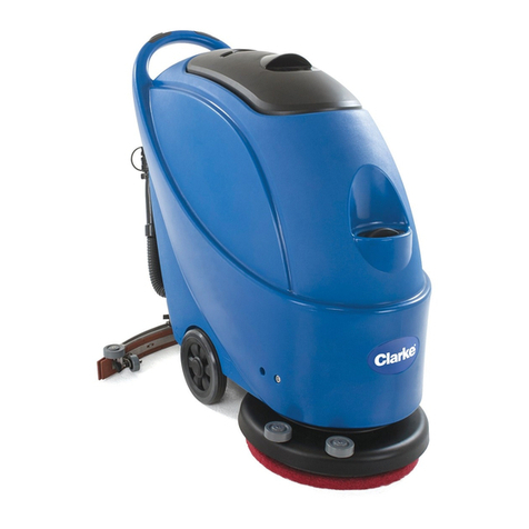
Tennant 7200 Training manual
Other Tennant Scrubber manuals

Tennant
Tennant 810D User manual

Tennant
Tennant NOBLES EX-SC-1020P User manual

Tennant
Tennant T20 LPG Operating and installation instructions

Tennant
Tennant 800D User manual

Tennant
Tennant Alfa Mini LPTB02097 User manual

Tennant
Tennant T16 Training manual

Tennant
Tennant 7100 User manual
Tennant
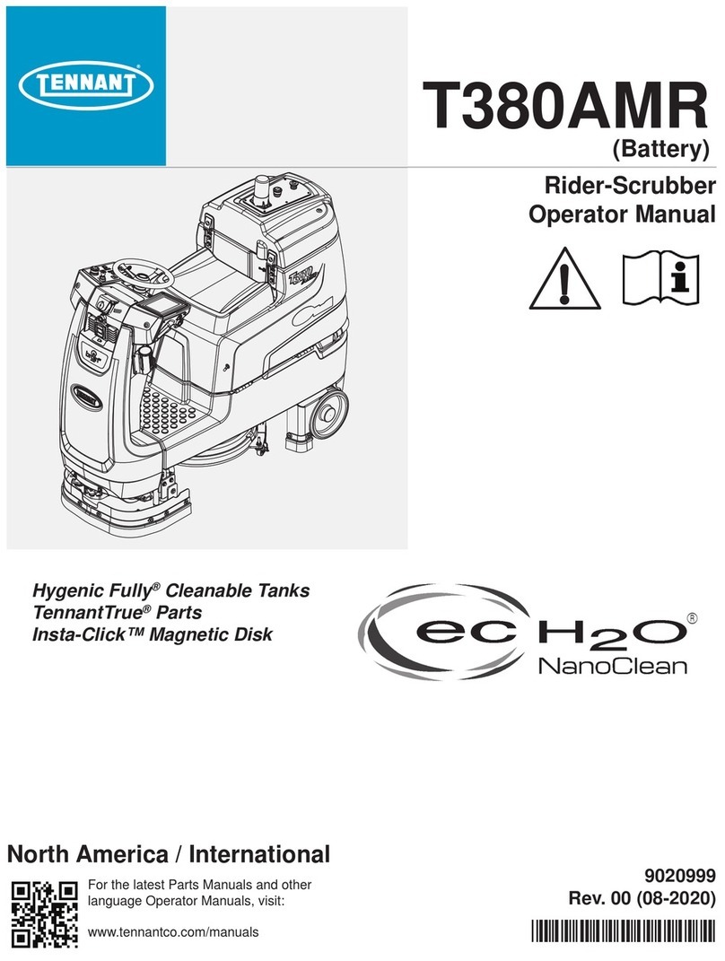
Tennant T380AMR User manual

Tennant
Tennant T291 User manual
Tennant
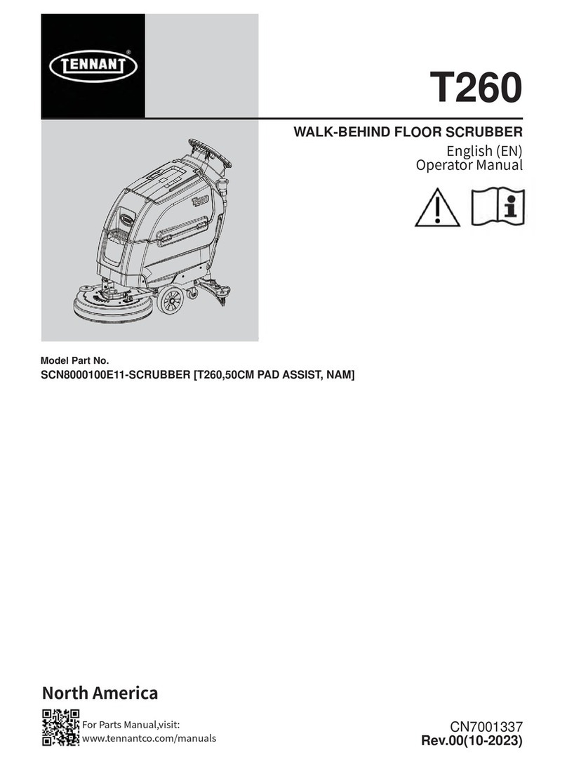
Tennant T260 User manual
Tennant
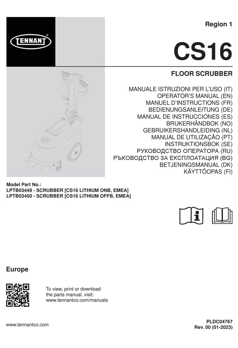
Tennant CS16 User manual

Tennant
Tennant i-mop Lite User manual

Tennant
Tennant T17 Series Training manual

Tennant
Tennant M30 Operating and installation instructions

Tennant
Tennant T3 User manual
Tennant
Tennant SweepSmart S20 ELECTRIC Training manual

Tennant
Tennant CS16 Operating manual

Tennant
Tennant T291 User manual

Tennant
Tennant IRIS T300 User manual
Tennant
Tennant ec H2O NanoClean T350 Operating and installation instructions
Popular Scrubber manuals by other brands

Numatic
Numatic TTB 4045/100 Original instructions

U.S. Products
U.S. Products PEX 500-C-TICK Information & operating instructions

Mclennan
Mclennan C510 Operator's manual

Columbus
Columbus ARA 66 BM 100 operating manual

Numatic
Numatic TTV 678G / 300T Owner's instructions

American-Lincoln
American-Lincoln 505-945 Instructions for use


