Tennant T12 User manual

T12
*9009918*
9009918
Rev. 05 (6-2016)
(Battery)
The Safe Scrubbing AlternativeR
TennantTrueRParts
IRISRa Tennant Technology
Insta−FittAdapter
Rider Scrubber
English EN
Operator Manual
R
For the latest parts manuals and other
language Operator manuals, visit:
www.tennantco.com/manuals

INTRODUCTION
This manual is furnished with each new model. It provides necessary operation and maintenance instructions.
Read this manual completely and understand
the machine before operating or servicing it.
This machine will provide excellent service. However, the best results will be obtained at minimum costs if:
SThe machine is operated with reasonable care.
SThe machine is maintained regularly - per the machine maintenance instructions provided.
SThe machine is maintained with manufacturer supplied or equivalent parts.
Model No. −
Serial No. −
Installation Date −
Please fill out at time of installation for future reference.
MACHINE DATAPROTECT THE ENVIRONMENT
Please dispose of packaging
materials, used components
such as batteries and fluids in
an environmentally safe way ac-
cording to local waste disposal
regulations.
Always remember to recycle.
INTENDED USE
The T12 is an industrial/commercial rider machine designed to wet scrub both rough and smooth hard surfaces
(concrete, tile, stone, synthetic, etc). Typical applications include schools, hospitals / health care facilities, office
buildings, and retail centers. Do not use this machine on soil, grass, artificial turf, or carpeted surfaces. This
machine is intended for indoor use only. This machine is not intended for use on public roadways. Do not use this
machine other than described in this Operator Manual.
Tennant N.V.
Industrielaan 6 5405 AB
P.O. Box 6 5400 AA Uden−The Netherlands
www.tennantco.com
Specifications and parts are subject to change without notice.
Original Instructions, copyright E2013 −2016 TENNANT Company, Printed in U.S.A.

CONTENTS
1
T12 9009918 (1−2016)
CONTENTS
Page
IMPORTANT SAFETY INSTRUCTIONS −
SAVE THESE INSTRUCTIONS 4.........
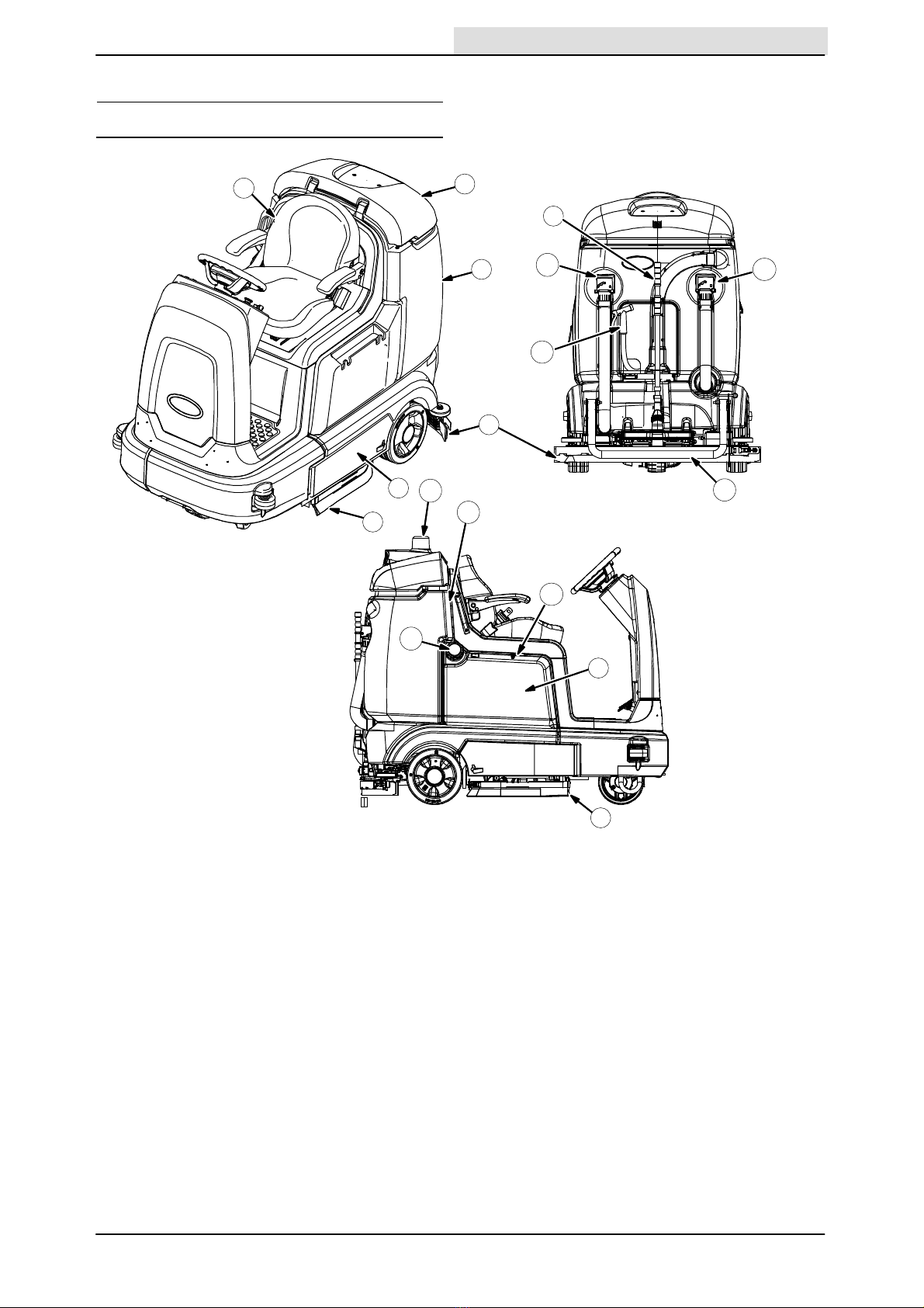
OPERATION 7.
MACHINE COMPONENTS 7.............
CONTROLS AND INSTRUMENTS (T12) 8.
TOUCH PANEL (T12) 9..................
CONTROLS AND INSTRUMENTS
(T12XP) 10
TOUCH PANEL (T12XP) 11...............
SYMBOL DEFINITIONS 12................
INSTALLING BATTERIES 13..............
OPERATION OF CONTROLS 14..........
BATTERY DISCHARGE INDICATOR 14.
HOUR METER 14.....................
RECOVERY TANK FULL INDICATOR 14.
EMERGENCY SHUT−OFF BUTTON 15.
OPERATING / HAZARD LIGHT SWITCH
(OPTION) 15......................
OPERATOR SEAT 16..................
SEAT BELTS (Deluxe Seat Option Only) 16
SEAT SUPPORT 16...................
CONTRAST CONTROL BUTTON 17....
CONFIGURATION MODE BUTTON 17..
PROPEL PEDAL 17...................
DIRECTIONAL SWITCH 17............
BRAKE PEDAL 17....................
VACUUM FAN / SQUEEGEE BUTTON 18
SOLUTION ON / OFF BUTTON 18......
HOW THE MACHINE WORKS 18..........
BRUSH AND PAD INFORMATION 19......
WHILE OPERATING THE MACHINE 20....
PRE−OPERATION CHECKLIST 20.........
STARTING THE MACHINE 21.............
FILLING THE SOLUTION TANK 21........
ec−H2O SCRUBBING (ec−H2O MODE) 21
CONVENTIONAL SCRUBBING MODE 22
ec−H2O BUTTON (OPTION) 22...........
SETTING BRUSH PRESSURE 23.........
SETTING SOLUTION FLOW 23...........
SCRUBBING 24.........................
DOUBLE SCRUBBING 25.................
WATER PICKUP MODE
(NO SCRUBBING) 26..................
STOP SCRUBBING 26...................
DRAINING AND CLEANING THE
RECOVERY TANK 27.................
DRAINING AND CLEANING THE
SOLUTION TANK 29..................
TURN OFF THE MACHINE 30.............
FAULT INDICATOR(S) 31.................
WARNING CODES 32....................
OPTIONS 33.
SPRAY NOZZLE (OPTION) 33..........
VACUUM WAND (OPTION) 34..........
REAR SQUEEGEE GUARD (OPTION) 35
SIDE BRUSH (OPTION) 36............
ADJUSTING BACKUP ALARM VOLUME
(OPTION) 36.........................
MACHINE TROUBLESHOOTING 37.......
Page
MAINTENANCE 40.........................
MAINTENANCE CHART 40...............
YELLOW TOUCH POINTS 42.............
LUBRICATION 42........................
STEERING CHAIN (T12XP ONLY) 42...
STEERING GEAR CHAIN 42...........
REAR SQUEEGEE CASTERS 42.......
BATTERIES 43
CHECKING THE ELECTROLYTE LEVEL
(WET / LEAD ACID
BATTERIES ONLY) 43...........
CHECKING CONNECTIONS /
CLEANING 43.....................
GEL BATTERIES 43...................
CHARGING THE BATTERIES
(OFF−BOARD CHARGER) 44.......
BATTERY WATERING SYSTEM
(OPTION) 45......................
CIRCUIT BREAKERS 46..................
ELECTRIC MOTORS 47.................
SCRUB BRUSHES 48....................
DISK BRUSHES AND PADS 48.........
REPLACING DISK BRUSHES OR
PAD DRIVERS 48..................
REPLACING DISK SCRUB PADS 49....
CYLINDRICAL BRUSHES 50...........
REPLACING CYLINDRICAL SCRUB
BRUSHES 50......................
SIDE BRUSH (OPTION) 51...............
REPLACING THE SIDE BRUSH 51.....
SQUEEGEE BLADES 52.................
REPLACING (OR ROTATING) THE
REAR SQUEEGEE BLADES 52......
LEVELING THE REAR SQUEEGEE 55..
ADJUSTING THE REAR SQUEEGEE
BLADE DEFLECTION 56............
REPLACING OR ROTATING THE SIDE
SQUEEGEE BLADES 57............
REPLACING OR ROTATING THE
SIDE BRUSH SQUEEGEE BLADES
(OPTION) 58....................
SKIRTS AND SEALS 60..................
RECOVERY TANK SEAL 60............
SCRUB HEAD SKIRTS (DISK SCRUB
HEADS ONLY) 60..................
BELTS 60.
CYLINDRICAL BRUSH DRIVE BELTS 60
TIRES 60.
PUSHING, TOWING, AND TRANSPORTING
THE MACHINE 61.....................
PUSHING OR TOWING THE MACHINE 61.
TRANSPORTING THE MACHINE 61.......
MACHINE JACKING 63...................
ec−H2O MODULE FLUSH PROCEDURE 64
STORAGE INFORMATION 66.............
FREEZE PROTECTION 66.............
PREPARING THE MACHINE FOR
OPERATION AFTER STORAGE 68..
PRIMING THE ec−H2O SYSTEM 70.......

CONTENTS
T12 9009918 (1−2016)
2
Page
SPECIFICATIONS 72.......................
GENERAL MACHINE
DIMENSIONS/CAPACITIES 72.........
GENERAL MACHINE PERFORMANCE 73..
POWER TYPE 73........................
TIRES 73.
STANDARD SOLUTION FLOW RATE 73...
SIDE BRUSH SOLUTION FLOW RATE
(OPTION) 73.........................
ec−H2O SYSTEM (OPTION) 74...........
MACHINE DIMENSIONS 74...............

SAFETY PRECAUTIONS
3
T12 9009918 (3−2013)

SAFETY PRECAUTIONS
T12 9009918 (6−2016)
4
IMPORTANT SAFETY INSTRUCTIONS −SAVE THESE INSTRUCTIONS
The following precautions are used throughout
this manual as indicated in their description:
WARNING: To warn of hazards or unsafe
practices that could result in severe
personal injury or death.
FOR SAFETY: To identify actions that must be
followed for safe operation of equipment.
The following information signals potentially
dangerous conditions to the operator. Know when
these conditions can exist. Locate all safety
devices on the machine. Report machine damage
or faulty operation immediately.
WARNING: Batteries emit hydrogen gas.
Explosion or fire can result. Keep
sparks and open flame away. Keep
covers open when charging.
WARNING: Flammable materials can
cause an explosion or fire. Do not use
flammable materials in tank(s).
WARNING: Flammable materials or
reactive metals can cause an explosion
or fire. Do not pick up.
WARNING: Electrical Hazard
−Disconnect Battery Cables and
Charger Plug Before Servicing
Machine.
−Do Not Charge Batteries with Damaged
Power Supply Cord. Do Not Modify
Plug.
If the charger supply cord is damaged or
broken, it must be replaced by the
manufacturer or its service agent or a similarly
qualified person in order to avoid a hazard.
FOR SAFETY:
1. Do not operate machine:
−Unless trained and authorized.
−Unless operator manual is read and
understood.
−Under the influence of alcohol or
drugs
−While using a cell phone or other
types of electronic devices
−Unless mentally and physically
capable of following machine
instructions.
−With brake disabled.
−If it is not in proper operating
condition.
−With pads or accessories not supplied
or approved by Tennant. The use of
other pads may impair safety.
−In areas where flammable
vapors/liquids or combustible dusts
are present.
−In areas that are too dark to safely see
the controls or operate the machine
unless operating / headlights are
turned on.
−In areas with possible falling objects
unless equipped with overhead guard.
2. Before starting machine:
−Check machine for fluid leaks.
−Keep sparks and open flame away
from refueling area.
−Make sure all safety devices are in
place and operate properly.
−Check brakes and steering for proper
operation.
−Adjust seat and fasten seat belt (if
equipped).
3. When using machine:
−Use only as described in this manual.
−Use brakes to stop machine.
−Go slowly on inclines and slippery
surfaces.
−Reduce speed when turning.
−Keep all parts of body inside operator
station while machine is moving.
−Always be aware of surroundings
while operating machine.
−Use care when reversing machine.
−Keep children and unauthorized
persons away from machine.
−Do not carry passengers on machine.
−Always follow safety and traffic rules.
−Report machine damage or faulty
operation immediately.
−Follow mixing, handling and disposal
instructions on chemical containers.
−Follow site safety guidelines
concerning wet floors.
−Follow site safety guidelines
concerning backup alarms.
−Do not scrub on ramp inclines that
exceed 7% grade or transport (GVWR)
on ramp inclines that exceed 14.1%
grade.

SAFETY PRECAUTIONS
5
T12 9009918 (8−2014)
4. Before leaving or servicing machine:
−Stop on level surface.
−Turn off machine and remove key.
5. When servicing machine:
−All work must be done with sufficient
lighting and visibility.
−Avoid moving parts. Do not wear loose
clothing, jewelry and secure long hair.
−Block machine tires before jacking
machine up.
−Jack machine up at designated
locations only. Support machine with
jack stands.
−Use hoist or jack that will support the
weight of the machine.
−Do not push or tow the machine on
inclines with the brake disabled.
−Do not push or tow the machine
without an operator in the seat
controlling the machine.
−Do not power spray or hose off
machine near electrical components.
−Disconnect battery connections before
working on machine.
−Avoid contact with battery acid.
−Battery installation must be done by
trained personnel.
−All repairs must be performed by a
trained service mechanic.
−Do not modify the machine from its
original design.
−Use Tennant supplied or approved
replacement parts.
−Wear personal protective equipment
as needed and where recommended in
this manual.
−Disconnect battery connections and
charger cord before working on
machine.
−Keep all metal objects off batteries.
−Use a non−conductive battery removal
device.
−Use a hoist and adequate assistance
when lifting batteries.
−Follow site safety guidelines
concerning battery removal.
−Do not disconnect the off−board
charger’s DC cord from the machine
receptacle when the charger is
operating. Arcing may result. If the
charger must be interrupted during
charging, disconnect the AC power
supply cord first.
−Do not use incompatible battery
chargers as this may damage battery
packs and potentially cause a fire.
For Safety: wear hearing protection.
For Safety: wear protective gloves.
For Safety: wear eye protection.
For Safety: wear protective dust mask.
6. When loading/unloading machine
onto/off truck or trailer.
−Drain tanks before loading machine.
−Lower scrub head and squeegee
before tying down machine.
−Turn off machine and remove key.
−Use ramp, truck or trailer that will
support the weight of the machine and
operator.
−Use winch. Do not push the machine
onto/off the truck or trailer unless the
load height is 380 mm (15 in) or less
from the ground.
−Block machine tires.
−Tie machine down to truck or trailer.
−Do not load/unload on ramp inclines
that exceed 20% grade.

SAFETY PRECAUTIONS
T12 9009918 (8−2014)
6
The safety labels appear on the machine in the
locations indicated. Replace damaged labels.
WARNING LABEL −
Batteries emit hydrogen
gas. Explosion or fire
can result. Keep sparks
and open flame away.
Keep covers open when
charging
FOR SAFETY LABEL −
Read manual before
operating machine.
WARNING LABEL −
Flammable materials or reactive
metals can cause explosion or fire.
Do not pick up.
Located on
electrical panel.
Located on electrical panel.
Located inside
battery compartment.
WARNING LABEL −
Flammable materials
can cause explosion
or fire. Do not use
flammable materials
in tank
Located on recovery
tank, above solution
tank cap.
FOR SAFETY LABEL −
Authorized Service Mechanic Only.
Located on circuit board cover and
electrical panel.
356290

OPERATION
7
T12 9009918 (6−2016)
OPERATION
MACHINE COMPONENTS
B
G
A
F
C
M
N
P
O
E
HI
J
K
L
D
Q
356289/356290
A Operator seat
B Recovery tank cover
C Recovery tank
D Rear squeegee
E Main brush compartment
F Side squeegee
G Vacuum wand (Option)
H Solution tank drain hose
I Recovery tank drain hose
J Spray nozzle (Option)
K Rear squeegee protector (Option)
Lec−H20 System Module
compartment (Option) −located behind
seat shroud
M Battery compartment
N Solution tank cap
O Solution tank
P Scrub head
Q Backup alarm / flashing light (Option)

OPERATION
8T12 9009918 (3−2013)
CONTROLS AND INSTRUMENTS (T12)
A
D
B
C
H
G
J
E
F
I
A Steering wheel
B Touch panel
C Propel pedal
D Brake pedal
E Spray nozzle switch (Option)
F Operating lights / hazard lights
switch (Option)
G Side brush switch (Option)
H Key switch
I Direction switch
J Emergency shut−off button

OPERATION
9
T12 9009918 (3−2013)
TOUCH PANEL (T12)
A
J
BCE
D
G
F
I
LM
N
O
R
H
K
P
Q
A Contrast control button
B Battery discharge indicator
C Warning / fault indicator light
D LCD display
E Hour meter
F Configuration mode button
G Recovery tank full indicator
H Brush pressure decrease button (−)
I Brush pressure indicator lights
J Brush pressure increase button (+)
K Solution decrease button (−)
L Solution flow indicator lights
M Solution increase button (+)
Nec−H2O button
O Vacuum fan / squeegee button
P Solution On / Off buttons
Q1−Step button
R Horn

OPERATION
10 T12 9009918 (3−2013)
CONTROLS AND INSTRUMENTS (T12XP)
H
B
A
D
C
E
F
GI
J
A Steering wheel
B Touch panel
C Propel pedal
D Brake pedal
E Emergency shut−off button
F Directional switch
G Key switch
H Spray nozzle switch (option)
I Side brush switch (option)
J Operating lights / hazard lights
switch (option)

OPERATION
11
T12 9009918 (3−2013)
TOUCH PANEL (T12XP)
A
I
B
E
L
C
F
G
H
KM
N
O
P
D
J
Q
P
A Horn
B Warning / fault indicator light
C Battery discharge indicator
D Hour meter
E Configuration mode button
F Recovery tank full indicator
G LCD display
H Contrast control button
I Brush pressure button
J Brush pressure indicator lights
K1−Step button
Lec−H2O button
M Vacuum fan / squeegee button
N Solution increase button (+)
O Solution decrease button (−)
P Solution on / off buttons
Q Solution flow indicator lights

OPERATION
12 T12 9009918 (3−2013)
SYMBOL DEFINITIONS
These symbols are used on the machine to
identify controls, displays, and features.
Fault indicator Recovery tank
Vacuum fan / squeegee Operating lights
1−STEP Hazard light
ec−H2O (option) Scrub mode
Solution flow Circuit breaker
Increase Spray nozzle (option)
Decrease On
Main brush pressure Off
Side brush (option) Solution On / Off
Battery charge Emergency shut−off
Horn Contrast control
Hour meter Jack point
Solution tank Solution flow (maximum / minimum)
Forward / Reverse Brush pressure (maximum / minimum)

OPERATION
13
T12 9009918 (7−2013)
INSTALLING BATTERIES
WARNING: Fire Or Explosion Hazard.
Batteries Emit Hydrogen Gas. Keep
Sparks And Open Flame Away. Keep
Battery Hood Open When Charging.
FOR SAFETY: When servicing machine, wear
protective gloves and eye protection when
handling batteries and battery cables. Avoid
contact with battery acid. Battery installation
must be done by trained personnel.
1. Park the machine on a level surface and
remove the key.
2. To engage the seat support, lift the seat
completely open until the pin slides into the
lower notch of the seat support.
Machines with deluxe seat option only: Pull and
hold the Operator seat release handle forward to
unlock the seat before lifting the seat open.
3. Carefully install the batteries into the battery
compartment tray and arrange the battery
posts as shown. Insert the foam spacers
along side the batteries as shown if installing
the smaller batteries.
NOTE: For large traction batteries, remove the
seat assembly and use a hoist to install the
battery.
Front of machine
Foam Spacer
Foam SpacerFoam Spacer
Foam Spacer
4. Using the supplied battery post boots, connect
the cables to the battery posts,
RED TO POSITIVE (+) & BLACK TO
NEGATIVE (−).

OPERATION
14 T12 9009918 (3−2013)
OPERATION OF CONTROLS
BATTERY DISCHARGE INDICATOR
The Battery discharge indicator displays the
charge level of the batteries while the machine is
operating.
T12 T12XP
When the batteries are fully charged, all five bars
are lit. Recharge the batteries when there is only
one bar shown in the display. Do not allow the
batteries to discharge below 20% (last bar).
NOTE: The reading on the battery discharge
indicator is not accurate when the machine is first
powered on. Operate the machine a few minutes
before reading the charge level of the batteries.
NOTE: The flashing Warning / fault indicator and
battery low fault in the LCD (liquid crystal display)
will not reset until after the batteries have been
fully charged. See FAULT INDICATOR(S).
HOUR METER
The Hour meter records the hours the machine
was operated. Use this information to determine
machine service intervals.
T12 T12XP
RECOVERY TANK FULL INDICATOR
The Recovery tank full indicator displays 0% when
the recovery tank is not yet full and 100% when
the recovery tank is full. All scrubbing functions
will stop when the recovery tank is full. Empty the
recovery tank when the indicator displays 100%.
T12 T12XP

OPERATION
15
T12 9009918 (3−2013)
EMERGENCY SHUT−OFF BUTTON
The Emergency shut−off button immediately stops
all power to the machine.
Stop machine power: Push the Emergency
shut−off button.
Restart machine power: Turn the Emergency
shut−off button to the right to release the button.
Turn the key switch to the Off position, then turn
the key fully clockwise and release it to the On
position.
Only use this button in the event of an emergency.
It is not intended for routine machine shutdown.
OPERATING / HAZARD LIGHT SWITCH
(OPTION)
Operating and Hazard Lights On: Press the top of
the Operating / hazard light switch.
Hazard Lights On: Press the Operating / hazard
light switch to the middle position.
All Lights Off: Press the bottom of the Operating /
hazard light switch.
T12
T12XP

OPERATION
16 T12 9009918 (3−2013)
OPERATOR SEAT
The front−to−back adjustment lever adjusts the
seat position.
SEAT BELTS (Deluxe Seat Option Only)
FOR SAFETY: Before starting machine, adjust
seat and fasten seat belt.
SEAT SUPPORT
The Seat support holds the seat up to allow
access to the batteries and circuit breakers.
To engage the seat support, lift the seat
completely open until the pin slides into the lower
notch of the seat support.
Machines with deluxe seat option only: Pull
and hold the Operator seat release handle
forward to unlock the seat before lifting the
seat open.

OPERATION
17
T12 9009918 (3−2013)
CONTRAST CONTROL BUTTON
Use the Contrast control button to darken / lighten
the LCD display.
T12 T12XP
CONFIGURATION MODE BUTTON
The Configuration mode button is for accessing
the configuration and diagnostic modes. Only
properly trained service personnel and TENNANT
representatives should access these modes.
T12 T12XP
PROPEL PEDAL
Press the Propel pedal to move the machine.
DIRECTIONAL SWITCH
Use the Directional switch to select either the
forward or reverse direction. Press the propel
pedal to move the machine.
NOTE: An audible alarm will sound when the
Directional switch is placed into reverse.
NOTE: Machines equipped with the optional
flashing light / backup alarm only: The optional
backup light and alarm will function only when the
machine is moving in reverse.
BRAKE PEDAL
Press the Brake pedal to stop the machine.

OPERATION
18 T12 9009918 (3−2013)
VACUUM FAN / SQUEEGEE BUTTON
Lower squeegee and turn vacuum fan on: Press
the Vacuum fan / squeegee button. The indicator
light will illuminate when the squeegee is lowered.
Raise squeegee and turn vacuum fan off: Press
the Vacuum fan / squeegee button. The indicator
light will go out when the squeegee is raised.
NOTE: The 1−STEP button does not need to be
activated to operate the vacuum fan / squeegee
system. The vacuum fan / squeegee button can
be turned on or turned off with the 1−STEP button
either on or off.
T12 T12XP
SOLUTION ON / OFF BUTTON
Shut off the solution flow: Press the Solution on /
off button to shut off the solution flow. All the
solution flow indicator lights will turn off.
Turn on the solution flow: Press the Solution on /
off button to turn on the solution flow. The solution
indicator lights will turn back on and the solution
flow will default to the last setting used.
T12 T12XP
HOW THE MACHINE WORKS
T12 With Cylindrical Brushes
T12 With Disk Brushes
The 1−STEP button makes it possible to
immediately begin scrubbing by operating all the
scrubbing functions.
When in the conventional Scrub mode, a water
and detergent mixture is used to scrub the floor.
When in the optional ec−H2O (electrically
converted water) mode, normal water passes
through a module where it is oxygenated and
charged with an electric current. The electrically
converted water changes into a blended acidic
and alkaline solution forming a neutral pH cleaner.
The converted water attacks the dirt, breaks it into
smaller particles, and pulls it off the floor surface
allowing the machine to easily scrub away the
suspended soil. The converted water then returns
to normal water in the recovery tank. The ec−H2O
system can be used with all double scrubbing and
heavy duty scrubbing applications.
Other manuals for T12
7
Table of contents
Other Tennant Scrubber manuals

Tennant
Tennant T2 User manual

Tennant
Tennant SweepSmart S20 ELECTRIC Training manual

Tennant
Tennant CS16 User manual

Tennant
Tennant M20 User manual

Tennant
Tennant T16 Training manual

Tennant
Tennant Speed Scrub ES KIT 2701 User manual

Tennant
Tennant t500e User manual

Tennant
Tennant CS16 User manual

Tennant
Tennant M30 User manual

Tennant
Tennant 385DLH User manual

Tennant
Tennant T20 LPG User manual

Tennant
Tennant IRIS T300 User manual

Tennant
Tennant 7100 Training manual

Tennant
Tennant T3 User manual

Tennant
Tennant T20 LPG User manual

Tennant
Tennant T300e User manual

Tennant
Tennant 5680 User manual

Tennant
Tennant CS16 User manual

Tennant
Tennant T5 User manual

Tennant
Tennant T291 User manual