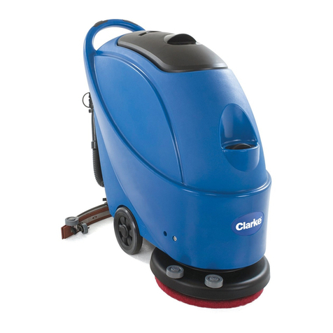
Tennant M20 Training manual

IB 9015637 (03- 2020) 1
INSTRUCTION BULLETIN
No. 9015637
Machine: M20/T20/
M30/M17
Published: 03- 2020
Rev. 01
NOTE: DO NOT DISCARD the Parts List from the Instruction Bulletin. Place the
Parts List in the appropriate place in the machine manual for future
reference. Retaining the Parts List will make it easier to reorder
individual parts and will save the cost of ordering an entire kit.
NOTE: Numbers in parenthesis ( ) are reference numbers for parts listed in Bill of Materials.
Installation instructions for kit number 9015633/9015042
SYNOPSIS:
This kit contains the parts needed to replace Pro- Panel assembly on M17/M20/M30/T20 machines.
Please follow step-by-step instructions.
SPECIAL TOOLS / CONSIDERATIONS: NONE
(Estimated time to complete: 45- 60 minutes)
PROTECT THE ENVIRONMENT
Please dispose of packaging materials, used machine components
such as batteries and fluids in an environmentally safe way according
to local waste disposal regulations.
Always remember to recycle.
PREPARATION (M20/M30/T20 ONLY):
1. If the pod assembly on machine is operable,
connect service computer to the pod, turn the
key to the ON position, but do not start the
machine, start the Capture application, and
note machine settings. The new pod
assembly (1) will need to be configured to the
same settings.
FOR SAFETY: Before leaving or servicing
machine, stop on level surface, turn off
machine, set parking brake, and remove key.
2. Disconnect the battery cables from the
battery.
WARNING: Always disconnect battery
cables from machine before working on
electrical components.
3. Open the front shroud to access the steering
mechanism components.
INSTALLATION (M20/M30/T20 ONLY):
1. Disconnect the pod cables from the main wire
harness. (Fig. 1)
FIG. 1

IB 9015637 (03- 2020)2
2. Loosen the socket screws (Qty. 2) securing
the pod assembly into the steering tilt bracket.
(Fig. 2/Fig. 3)
FIG. 2
3. Pull the pod assembly out from the steering
assembly. (Fig. 3)
4. Remove the two thrust washers from the pod
assembly. Set the thrust washers aside.
Discard the removed pod assembly. (Fig. 3)
5. Slide the thrust washers onto the new pod
assembly (1). (Fig. 3)
6. Insert the new pod assembly (1) into the
steering assembly. (Fig. 3)
7. Orient the pod assembly (1) so the display is
positioned correctly in the steering wheel and
tighten the two socket screws to secure the
pod assembly into the steering tilt bracket.
(Fig. 2/Fig. 3)
8. Connect the pod assembly (1) to the main
wire harness.
9. Reconnect the battery cables to the battery.
1
Thrust
washers
(Qty. 2)
Steering
wheel
Steering
tilt bracket
FRONT
FIG. 3

IB 9015637 (03- 2020) 3
PREPARATION (M17 ONLY):
1. If pod assembly on machine is operable,
connect service computer to the pod, turn the
key to the ON position, start the Capture
application, and note machine settings. The
new Pro- Panel pod assembly (1) must be
configured to the same settings.
NOTE:If Pro- Panel pod assembly is completely
inoperable, the machine configuration settings will
need to be set to the optional equipment on the
machine and / or set to the standard default
settings.
2. If pod assembly on machine is operable,
record the hours from the hour meter.
FOR SAFETY: Before leaving or servicing
machine, stop on level surface, turn off
machine, set parking brake, and remove key.
3. Disconnect the battery cable from the
machine.
WARNING: Always disconnect battery
cables from machine before working on
electrical components.
4. Remove the electrical access panel from the
machine. Set the electrical access panel and
all hardware aside. (Fig. 4)
FIG. 4
INSTALLATION (M17 ONLY):
1. Disconnect the main wire harness and rear
view camera cable from the Pro- Panel pod
assembly. (Fig. 6)
2. Loosen the M6 set screws securing the
Pro- Panel pod assembly in the bearing plate.
(Fig. 5/Fig. 6)
FIG. 5
3. Pull the Pro- Panel pod assembly from the
steering mechanism. (Fig. 6)
4. Remove both thrust washers from the
Pro- Panel pod assembly. Set the thrust
washers aside. Discard the Pro- Panel pod
assembly. (Fig. 6)
5. Slide the thrust washers onto the new
Pro- Panel pod assembly (1). (Fig. 6)
6. Carefully insert the Pro- Panel pod assembly
(1) into the steering mechanism. Do Not
damage cables when inserting the Pro- Panel
pod into the steering mechanism. (Fig. 6)
7. Position the Pro- Panel pod assembly (1) so it
is properly aligned on the steering wheel.
(Fig. 6)
8. Tighten the two M6 set screws to secure the
Pro- Panel pod assembly (1) inside the
bearing plate. (Fig. 5/Fig. 6)
9. Connect the main wire harness and the rear
view camera cable to the Pro- Panel pod
assembly (1). (Fig. 6)
10. Reinstall the electrical access panel onto the
machine.
11. Reconnect the battery cable to the machine.

IB 9015637 (03- 2020)4
FRONT
1
Loosen M6
set screws
(Qty. 2)
*Bearing
plate
Thrust
washers
(Qty. 2)
Inductor (CE /
Australia Only): Install
onto new Pro- Panel
pod assembly (1)
To: Rear view
camera
To: Main wire
harness
*DoNot removebearingplate from machine/steeringmechanism when replacing Pro- Panel pod
assembly (1). Parts shown disassembled to better show part locations
FIG. 6

IB 9015637 (03- 2020) 5
TENNANT SERVICE APPLICATION
SOFTWARE (ALL MACHINES):
Download the service application software as
described below.
For Tennant service personnel equipped with
ServiceLink computers, the software is already
installed on the service computer. The software
application is titled “Service Diagnostics”.
(Fig. 7)
Icon on
Desktop
From Start menu
From Start menu > All Programs > Tennant
Company > Tennant Service Diagnostics
FIG. 7
For other Service Groups, the Service
Application Software can be downloaded from the
Tennant Public website as described below.
NOTE: If the Service Application Software is
currently installed on the service computer,
confirm or reinstall the software to ensure latest
software version is installed.
To access the Service Application Software, go to
www.tennantco.com. Depending on geographic
location, the website may have a “Log in/Sign Up”
button at the upper right or a “My Tennant
Customer Sign In” tab at the upper right of the
Tennant website. (Fig. 8)
Proceed with the software download instructions
as described on the following pages.
Website with “Log In / Sign Up” button
(Access to “My Account”)
OR
Website with “My Tennant Customer Sign In” tab
(Access to My Tennant)
FIG. 8

IB 9015637 (03- 2020)6
Website with “Log In / Sign Up” button:
(Access to “My Account”) (ALL MACHINES):
1. Log in or Sign Up to create an account.
(Fig. 9)
FIG. 9
2. Once logged in to the “My Account” website,
click on the “INTERNAL RESOURCES” link.
(Fig. 10)
FIG. 10
3. Click on the “SERVICE APPLICATION
SOFTWARE” link. (Fig. 11)
FIG. 11
4. Within the Service Application Software page,
click on the link titled “Service Diagnostics
LE version 1.5.12” or later. (Fig. 9)
FIG. 12
5. To download the service software continue to
click as instructed then click the Save button.
(Fig. 13)
FIG. 13
6. Open the “Downloads” folder and locate the
“LE_Setup_xxxx” zip file. Open the zip file and
double click on the “LE_Setup_xxx” file to
install the application software on service
computer. Follow instructions on screen to
install. (Fig. 14)
FIG. 14
7. Proceed to PROGRAM THE CONTROL
BOARD.

IB 9015637 (03- 2020) 7
PROGRAM THE CONTROL BOARD
(ALL MACHINES):
If any problems are encountered during the
programming process, contact the Technical
Service Department for support.
1. Access the software through either the
desktop icon or the Start Menu. The software
application is titled “Service Diagnostics”.
(Fig. 15/Fig. 16/Fig. 17)
FIG. 15
From Start menu
FIG. 16
Start menu > All Programs > Tennant
Company > Tennant Service Diagnostics
FIG. 17
2. Start the Service Software Application
program. The following screen will appear.
(Fig. 18)
FIG. 18
3. Connect the USB cable to the computer and
the USB port on machine. Turn the key switch
to the ON position.
4. The application software will connect to the
machine. (Fig. 19)
FIG. 19
If the application remains on the “Connecting
to Machine...” screen for an extended period,
cycle key or close and restart the application
software. If it still fails to connect, restart the
computer.

IB 9015637 (03- 2020)8
5. The following screen appears when the
application software is connected to machine
(Fig. 20). Enter the machine serial number
from the label on machine (ex. M17-
12345678). Select the appropriate model from
the drop- down menu. Press the arrow button
to advance to next screen.
FIG. 20
6. Carefully select the correct installed options
on the machine (Fig. 21). This may require
visually inspecting the machine to confirm all
installed options. Press the arrow button to
advance to next screen.
NOTE: If the machine is configured with an option
it does not have, a fault code may appear during
machine start up.
FIG. 21
7. The application will begin configuring the new
control board. Allow the configuration process
to be completed. (Fig. 22)
FIG. 22
8. The Machine Setup Complete screen appears
after configuration is complete. (Fig. 23)
FIG. 23
9. Disconnect the USB cable from the machine
and turn key off. The machine is now ready
for operation.
10. Test machine to ensure all installed options
are functioning and no fault codes appear. If a
fault code appears, proceed to next step.
11. Reconnect the USB cable to the computer
and the machine. The Main Menu will appear
on the computer screen.

IB 9015637 (03- 2020) 9
12. Check the machine configuration selections
for incorrect installed options. Select the
Configuration button. (Fig. 24)
FIG. 24
13. Correct the installed options. (Fig. 25)
FIG. 25
14. Press the down arrow button to program the
machine. A green check appears next to the
down arrow button when programmed.
(Fig. 25)
15. Cycle key to apply the corrected configuration
setting.
NOTE:The hour meter on Gas / LPG does not
need to be reset. The newly installed pod will
automatically reset to the correct hour meter
reading based on the hour setting (engine run
time) from the engine.
16. Disconnect the USB cable from the machine.

IB 9015637 (03- 2020)10
RESET THE HOUR METER (ALL MACHINES):
NOTE: Screens included in this section of the IB
are screen from the M17. The same screens exist
for the M20/M30/T20 machines but may be
different in appearance or have slightly different
nomenclature.
1. Use the keypad to enter the supervisor mode
log in number into the display above the
keypad. Press the enter button when finished
entering the log in number. (Fig. 26)
NOTE: If necessary, call Field Service Support for
the service log in number.
FIG. 26
2. The supervisor mode screen should appear in
the display. Press the settings button to
access the settings screen. (Fig. 27)
FIG. 27
3. Select the Service Modes button to access
the service modes. If necessary use up and
down arrow buttons to scroll to the Service
Modes button. (Fig. 28)
FIG. 28
4. Use the left arrow button and right arrow
button to scroll to the Configuration Mode.
Press the Check Mark button to access the
configuration mode. (Fig. 29)
FIG. 29
5. Use the left arrow button and right arrow
button to scroll to the C16: Propel H.M.. Press
the Check Mark button to access the C16:
Propel H.M. log in. (Fig. 30)
FIG. 30

IB 9015637 (03- 2020) 11
6. Log in to the C16: Propel H.M. Screen (hour
meter reset password is 0000): Use the minus
(- ) button to enter 0 (zero) at first asterisk.
Use right arrow button to move to next
asterisk and again use the minus (- ) button to
enter 0 (zero). Repeat for the remaining
asterisks. Press the Check Mark button when
finished. (Fig. 31)
FIG. 31
7. Press the Check Mark button when finished
entering 0 (zero) at the last asterisk. (Fig. 31)
8. Reset the hour meter at the C17: Chg Prpl Hr
screen: Use the minus (- ) button and plus (+)
button to set/reset numbers and the right
arrow button to move to the next number. If
necessary, use left arrow button to move back
to previous number. (Fig. 32)
FIG. 32
NOTE:If hour meter can not be viewed due to
pod being inoperable call Field Service Support
for the hour meter time from last time the machine
was serviced.
9. Press the Check Mark button when finished
entering the time for the hour meter. (Fig. 32)
10. Turn key switch to OFF position to turn off the
machine/exit the Config Mode.
RESET THE HOPPER ROLL OUT (M17 ONLY):
1. Turn the key to the ON position and ensure
hopper is completely lowered and rolled in.
The hopper must be completely lowered and
rolled in (in the home position) before it can
be reset to the factory roll settings.
2. Use the keypad to enter the supervisor mode
log in number into the display above the
keypad. Press the enter button when finished
entering the log in number. The Service Mode
screen should appear in the display. (Fig. 33/
Fig. 34)
NOTE: If necessary, call Field Service Support for
the service log in number.
FIG. 33
3. Press the settings button. The Service Mode
setting screen should appear in the display.
(Fig. 34/Fig. 35)
FIG. 34

IB 9015637 (03- 2020)12
4. Use the down arrow button to scroll down to
the Service Modes button and select the
Service Modes button to access the service
modes. (Fig. 35)
FIG. 35
5. Use the left arrow button and right arrow
button to scroll to the Manual Mode. Press the
Check Mark button to access the manual
mode. (Fig. 36)
FIG. 36
6. Use the left arrow button to scroll to M:35
Fact SetRoll. Press the Check Mark button
once to enter M:35 and again to reset the
hopper roll out to the factory setting. (Fig. 37)
FIG. 37
7. Verify the value on the left closely matches
the value in the parentheses. (Fig. 37)
NOTE:The hopper factory roll out setting may
fluctuate +/- 0.002 when reset. This is normal.
8. Turn key switch to OFF position to turn off the
machine/exit the Manual Mode.
9. Retest machine to ensure all installed options
are functioning. Activate the rear view camera
to ensure it functions. Operate the machine
with the various scrub/sweep functions to
ensure all the controls/buttons function.
Raise, roll out, lower, and roll in the hopper to
ensure all hopper functions are operational.
Bill Of Materials For Panel Kit, Pod, Afmkt [M17, Touch Screen] - 9015042
Ref.
Tennant
Part No. Description Qty.
11215588 )Panel Assy [M17, UI, Touch Screen] 1
Bill Of Materials For Panel Kit, Pod, Afmkt [Pro, M20/M30/T20] - 9015633
Ref.
Tennant
Part No. Description Qty.
11225047 )Panel Assy [UI, Touchscreen] 1
TENNANT COMPANY
P. O. Box 1452
Minneapolis, MN 55440-1452
Other manuals for M20
7
This manual suits for next models
3
Other Tennant Scrubber manuals

Tennant
Tennant 5280 User manual

Tennant
Tennant 7100 User manual

Tennant
Tennant 5100 Product manual

Tennant
Tennant T600 EE User manual

Tennant
Tennant T20 LPG User manual

Tennant
Tennant 7300 Training manual

Tennant
Tennant T380AMR User manual

Tennant
Tennant T981 User manual

Tennant
Tennant T17 Series Training manual

Tennant
Tennant T20 LPG User manual

Tennant
Tennant T981 User manual

Tennant
Tennant CS16 Operating manual

Tennant
Tennant M30 User manual

Tennant
Tennant 5100 Product manual

Tennant
Tennant IRIS T300 User manual

Tennant
Tennant T5 User manual

Tennant
Tennant 550 Training manual

Tennant
Tennant T12 Training manual

Tennant
Tennant T5 User manual

Tennant
Tennant CS5 User manual