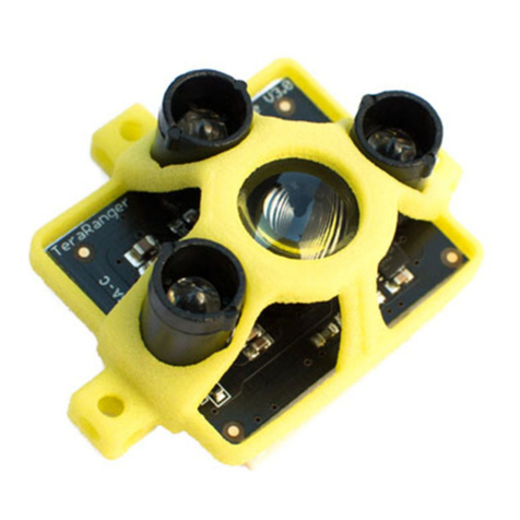
TeraBee TeraRanger Evo 64px User manual

User Manual for
TeraRanger Evo 64px with:
USB and UART backboard
Technical support: [email protected]

Table of contents:
1 Introduction 3
2 Mechanical integration 3
2.1 Mechanical design 4
2.2 Sensor handling during system assembly 4
3 USB backboard use 5
3.1 Graphical User Interface 5
3.1.1 Prerequisites 5
3.1.2 Basic Operation 5
4 UART backboard use 11
4.1 UART interface 11
4.2 Backboard LEDs 12
4.3 Electrical characteristics 12
5 Communication 13
5.1 UART protocol information 13
5.2 USB protocol information 13
5.3 Commands 13
5.4 UART / USB output format 14
6 Compliance 17
Appendix 18
A.1 CRC validation 18
A.1.1 How to calculate CRC8 checksum for Evo 64px 18
A.1.2 How to calculate CRC32 checksum for Evo 64px 18
A.2 Sample code 19
Copyright © Terabee 2018
Terabee, 90 Rue Henri Fabre
01630, St Genis-Pouilly, France (next to CERN)
2/22

1Introduction
The purpose of this document is to give guidelines for use and integration of the TeraRanger
Evo 64px multi-pixel sensor with (a) UART backboard, and/or (b) USB backboard using
these standard communication interfaces.
1.1 About TeraRanger Evo 64px
TeraRanger Evo64px is the multi-pixel Time-of-Flight sensor of the TeraRanger Evo product
family. It provides a matrix of 8x8 distance readings over a 15 degrees FOV, with a
maximum range up to 5m. The sensor offers two operating modes: select “Fast” mode with
sampling rates as high as 130 frames per second or choose “Close-range” mode for
improved minimum range, with measurements starting from 10 centimeters. Evo 64px
delivers depth data in a compact form-factor, weighing as little as 12 grams. The sensor
uses infrared LED technology, meaning it is fully eye-safe and also operates in low light or
dark conditions without the need for external illumination.
2Mechanical integration
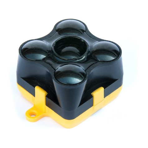
The mechanical design of the main sensor module (black) allows easy assembly to its
backboard (yellow) using a simple ‘clip-in’ technique. (When you clip the two together,
ensure there is no visible gap between the black and yellow parts.) The yellow backboard
has two mounting holes for final installation.
Figure 1. TeraRanger Evo two-part design
When choosing a place for mounting, please consider the following recommendations:
● Choose a place which is in accordance with the optical constraints listed below
● Mounting close to sources of heat or strong electromagnetic fields can decrease the
sensing performance
● Do not mount anything directly in front of the sensor or in a cone of approximately
±15° around the central optical axis of the sensor
● Within the first meter from the sensor, avoid objects with high surface reflectivity in a
cone of approximately ±45° around the central optical axis of the sensor
Copyright © Terabee 2018
Terabee, 90 Rue Henri Fabre
01630, St Genis-Pouilly, France (next to CERN)
3/22
● It is advisable to avoid having other sources of Continuous Wave or modulated IR
light close to the sensor
● Please consider that dust, dirt and condensation can affect the sensor’s performance
● It is not advised to add an additional cover in front of the sensor
● Drone rotor blades, or other environments with flickering (‘chopped’) ambient light in
the field of view can affect the sensor’s readings
2.1Mechanical design
Figure 2. TeraRanger Evo 64px external dimensions
2.2Sensor handling during system assembly
During assembly and integration, please observe all common ESD precautions. All optical
surfaces (sensor front) should be kept clean and free from contact with chemicals.
Copyright © Terabee 2018
Terabee, 90 Rue Henri Fabre
01630, St Genis-Pouilly, France (next to CERN)
4/22

3USB backboard use
The USB backboard comes with a standard Micro-USB connector.
3.1Graphical User Interface
A free Graphical User Interface (GUI) is available, providing an easy way to visualize the
data from your TeraRanger Evo 64px sensor. This is useful for demonstration, testing
purposes and checking some of the basic parameters of the sensor. It also provides a way
to easily export raw distance data and upgrade the firmware running on the device.
The GUI is available for download here: GUI Download. (See “Download” section of the
TeraRanger Evo 64px product page).
3.1.1
Prerequisites
For usage on Windows 7 and Windows 8, please download the Virtual COM Port driver from
http://www.st.com/en/development-tools/stsw-stm32102.html and follow the ”ReadMe file”
instructions given by the installer. After successful installation, unplug the interface for a
few seconds, and plug it back in. The virtual COM port should now be available on your PC.
Users of Windows 10 do not need to download this driver as the built in Windows driver is
recommended.
3.1.2
Basic Operation
During installation of the GUI, you might receive a notification from Windows about an
unknown application trying to start (Figure 3). In the “Windows protected your PC” screen
select More info > Run anyway to proceed with Evo 64px GUI installation and please be
advised that running this application will not put your PC at risk.
Copyright © Terabee 2018
Terabee, 90 Rue Henri Fabre
01630, St Genis-Pouilly, France (next to CERN)
5/22

Figure 3. Windows protection screen during installation
After successful installation, make sure your TeraRanger Evo 64px is connected to a USB
port on your computer. In the GUI select File > Connect (Ctrl+O). You will immediately see
64 distance readings displayed in a 8x8 pixel color map, labeled Depth Map (Figure 4).
Figure 4. Graphical user interface: home screen
On the right side of the depth map you will find a color vs distance (millimeters) scale. By
default the scale will automatically adjust the color code depending on the highest range
detected at time of data capture and remain until a higher distance is reached. The scale will
not automatically downscale in the event when the maximum distance in the pixel field
reduces. In order to reset it, select File > Reset Bounds.
Copyright © Terabee 2018
Terabee, 90 Rue Henri Fabre
01630, St Genis-Pouilly, France (next to CERN)
6/22

Figure 5. Auto vs manual distance bounds
To set custom distance bounds, in the GUI select File > Auto Distance Bounds > Disable
(Figure 5). You should now be able to input minimum and maximum bounds in millimeters in
the fields on the bottom left side of the screen. Select “Adjust” to apply changes, and your
color map will adjust according to the set values.
Figure 6. Fast vs Close Range mode
On the main interface, select between Fast mode and Close Range mode (Figure 6). Use
“Fast” mode and achieve sampling rates as high as 130 frames per second, or select “Close
Range” mode for improved minimum range, starting from 10 centimeters. For more
information on the TeraRanger Evo 64px’s operating modes please refer to the TeraRanger
Evo 64px specification sheet.
By default, the 64 distance readings visualized on the depth map are interpolated. To disable
interpolation of pixels and display values in discrete mode, select File > Interpolate >
Disable (Figure 7).
Copyright © Terabee 2018
Terabee, 90 Rue Henri Fabre
01630, St Genis-Pouilly, France (next to CERN)
7/22

Figure 7. Interpolate vs discrete mode
The GUI also offers the option to display the distance data in a 3 dimensional map
representation. Select File > View > 3D Plot, and a new window will now open with the 64
pixels represented in a 3D model. Choose to demonstrate the 3D model in a Plane or Mesh
view (Figure 8), both options can be selected at the bottom of the main GUI screen.
Figure 8. View data in a 3D plot: Plain vs Mesh view
Select File > View > Pixel Data and stream a matrix of 8x8 distance values in millimeters in
real-time. The “Pixel Data” option also streams 64 values of ambient level in real-time, which
is proportional to the target irradiance centered around 940nm. See Figure 9 for visual
instructions.
Copyright © Terabee 2018
Terabee, 90 Rue Henri Fabre
01630, St Genis-Pouilly, France (next to CERN)
8/22

Figure 9. Stream raw distance and ambient values in real-time
You can also choose to visualize the ambient values in an 8x8 pixel grayscale map by
selecting File > View > Ambient map. This can be useful in detecting other near-infrared
sources in your environment.
You can also export raw distance and ambient data in a text-format file, by selecting “Save”
on the main screen of the GUI. Next, you’ll be asked to save the text file in a location of your
preference. Afterwards a dialog window will appear offering to specify exact amount of
frames to be exported. Please note that one frame equals 64 distance values and 64
ambient values. Once this is specified, click “Save” and your text file will be exported. See
Figure 10 for visual instructions.
Figure 10. Export raw distance data
Figure 11 illustrates a text file of exported data with 3 frames. The first value in the row
always indicates the sequential number of the frame, followed by a header; 17 for distance
readings and 19 for ambient values. In the example above, the first row shows 64 distance
values in millimeters and the second row shows 64 values on near-infrared ambient; both
rows are part of frame number 1.
Copyright © Terabee 2018
Terabee, 90 Rue Henri Fabre
01630, St Genis-Pouilly, France (next to CERN)
9/22

Figure 11. Text file of raw data exported from GUI
Once you are done with testing the sensor, in the GUI select File > Disconnect (Ctrl+D),
the GUI will terminate its VCP connection with the sensor.
3.1.3
Firmware Upgrade
It is possible to upgrade the firmware running on your device if a new firmware version is
made available on the Terabee website. The current firmware version on your TeraRanger
Evo can be found by selecting Help > About
in the graphical user interface.
Please note the Upgrade Firmware feature is only supported on Windows 7, 8 and 10.
Please carefully follow the steps outlined below to avoid permanently disabling your device.
● Install the latest version of the TeraRanger Evo GUI on your computer available on
the “Download” section of Evo 64px product page of Terabee website.
● Download the latest firmware file from the Terabee website
● In the GUI Select File > Connect and then File > Upgrade Firmware
● You will be presented with a dialog window asking you to confirm your choice
● After confirming your choice, a new dialog window will present you with instructions
on selecting the firmware file and launching the upgrade process, read the
instructions carefully.
● Press Select File and select the new firmware file with Windows File Explorer
● Press Upgrade and wait until the operation finishes
● Close the Upgrade dialog box
Copyright © Terabee 2018
Terabee, 90 Rue Henri Fabre
01630, St Genis-Pouilly, France (next to CERN)
10/22

4UART backboard use
4.1UART interface
The TeraRanger Evo 64px can be controlled through UART interface. It uses a single 9 pin
Hirose DF13 connector for interfacing to the host system. The mating connector is a Hirose
DF13-9S-1.25C with crimping contacts DF13-2630SCF (tin) or DF13-2630SCFA (gold).
Please consider the mechanical stability of the mated connectors and avoid any kind of
excess force on the connector (during installation and once integrated) and follow the
recommendations in the Hirose DF13 series datasheet (available here:
https://www.hirose.com/product/en/products/DF13) to ensure a reliable connection.
The table below provides an overview of the pin out of the DF13 connector:
Pin out and description (According to DF13 datasheet)
Pin
Designator
Description
1
Tx
UART transmit output. 3.3V logic
2
Rx
UART receive input. 3.3V logic
3
GND
Power supply and interface ground
4
rfu
RESERVED FOR FUTURE USE
5
rfu
RESERVED FOR FUTURE USE
6
rfu
RESERVED FOR FUTURE USE
7
5V
+5V supply input
8
GND
Power supply and interface ground
9
rfu
RESERVED FOR FUTURE USE
Copyright © Terabee 2018
Terabee, 90 Rue Henri Fabre
01630, St Genis-Pouilly, France (next to CERN)
11/22

4.2Backboard LEDs
Five LEDs are mounted to give visual feedback on the sensor. Table below lists the
functionality of each LED:
LED
Description
PWR (orange)
Power indicator, on when 5V connected
Rx/Tx (red/green)
UART receive and transmit indicators
LED 0 / LED 1
For internal use only
4.3Electrical characteristics
DC electrical characteristics
Parameter
Minimum
Standard
Maximum
Power supply
Voltage input
4.75 V
5V
5.25 V
Current
consumption(*)
80 mA
-
250 mA
Interface logic
levels
(referenced to +3V3)
LOW
HIGH
-
2.3
1
-
* Values recorded while reading a target at 2m distance. NB: this value depends on ambient conditions, distance
and target reflectivity
Copyright © Terabee 2018
Terabee, 90 Rue Henri Fabre
01630, St Genis-Pouilly, France (next to CERN)
12/22

5 Communication
5.1UART protocol information
The UART communication for the TeraRanger Evo 64px uses a simple protocol via UART
depending on the backboard used with the sensor.
The communication parameters for UART are:
Baud Rate: 3000000
Data Bits: 8
Stop Bit(s): 1
Parity: None
HW Flow Control: None
5.2USB protocol information
The USB communication for the TeraRanger Evo 64px uses a simple protocol via USB
depending on the backboard used with the sensor.The communication parameters for the
USB VCP are:
Baud Rate: 115200
Data Bits: 8
Stop Bit(s): 1
Parity: None
HW Flow Control: None
5.3Commands
The user can send commands to configure the sensor to work in a specific mode. The frame
of the command is built concatenating 8 bit address of the TeraRanger Evo 64px, 4 bit
Command (CMD) code, 4 bit for data count (indicating how many bytes of data will follow), N
bytes of the data itself and a CRC-8 (8 bit) checksum of the entire frame in the last byte. The
layout is depicted in Figure 12.
Figure 12. Frame structure for Evo 64px commands
Copyright © Terabee 2018
Terabee, 90 Rue Henri Fabre
01630, St Genis-Pouilly, France (next to CERN)
13/22

The table below lists the commands, including address and CRC-8, that can be sent to the
sensor:
Command Name
Command Description
Command
Distance Print
The sensor outputs 64 distance values
0x00 11 02 4C
Distance Ambient
Print (Default)
The sensor outputs 64 distance values
and 64 ambient values
0x00 11 03 4B
Close Range Mode
(Default)
The sensor takes 2 subsequent
frames at different light modulation
frequencies and builds the final image
by picking the best pixels of the 2
frames. This provides distance
readings starting from 0.1 to 5m at a
reduced sampling rate.
0x00 21 01 BC
Fast Mode
If performance is driven by the reading
speed, the sensor can be set to work
in this mode. In Fast mode, obtain
distance values from 0.5 to 5m.
0x00 21 02 B5
Deactivate VCP
Output
Deactivate USB VCP Output
0x00 52 02 00 D8
Activate VCP Output
Activate USB VCP Output
0x00 52 02 01 DF
NB: Each command MUST be transmitted in a continuous stream ie. not byte by byte.
The TeraRanger Evo 64px will reply to the above commands with a four byte response. The
third byte of the response will contain either an ACK (0x00) or a NACK (0xFF) to indicate if
the sensor has acknowledged or not acknowledged the command. In the case of the UART
interface, the sensor will tolerate moderate buffer overruns but it is advisable to always wait
for a command reply before sending a new command.
5.4UART / USB output format
The TeraRanger Evo 64px by default outputs Distance and Ambient data. When
connected via UART, the sensor will immediately start outputting data on startup. However
when connected via USB, it is necessary to send the ACTIVATE USB OUTPUT
command as shown in commands table in section 5.3.
Copyright © Terabee 2018
Terabee, 90 Rue Henri Fabre
01630, St Genis-Pouilly, France (next to CERN)
14/22

Depending on the mode, each frame will output one or more data packets with each packet
identified by a header, for example in Distance & Ambient mode, the sensor will output two
frames containing 64 distance values and 64 ambient values followed by a CRC32 to secure
the data integrity on the transmission. The output format structure in Distance mode is
depicted in Figure 13.
Figure 13. Evo 64px output format structure
The frame transmission ends with a New Line character (1 byte). Each byte transmitted by
the sensor is categorised into two types, data and metadata
. Data is information from the
sensor itself and metadata provides information about the data eg. packet headers. In the
case of Data, the most significant bit of every byte is set to 1. And in the case of metadata
the most significant bit is 0.
ie. 0b1xxxxxxx ➔ this byte is a data byte
0b0xxxxxxx ➔ this byte is a metadata byte
For hardware reasons, the size of every frame transmitted by the sensor is a multiple of 4
therefore frames which are not multiples of 4 have padding appended.
Each frame has a CRC32 checksum appended to it to allow the end user to confirm data
integrity. The CRC32 used is CRC-32 MPEG 2 (Polynomial 0x4C11DB7 with initial value of
0xFFFFFFFF and Final Xor Value 0x0).
Please reference Appendix section for instructions on the following topics:
● CRC validation
● reading data from Evo 64px sensor (includes sample code in python).
Copyright © Terabee 2018
Terabee, 90 Rue Henri Fabre
01630, St Genis-Pouilly, France (next to CERN)
15/22

For data output structure please reference table below.
Header
Description
Structure
0x11 / 0d17
Distance: 64 distance measurements as
calculated by the sensor for each pixel
after temperature, ambient light and
distance correction.
14 bit integer * 64 * 2
Each pixel distance value is
transmitted as two bytes,
representing the hibyte and
the lobyte of the pixel value.
Hibyte first and lobyte
second.
The MSB of each byte
should be cleared to zero.
0x13 / 0d19
Ambient : 64 ambient measurements as
1
calculated by the sensor for each pixel
after an ambient measurement cycle.
12 bit integer * 64 * 2
Each pixel value is
transmitted as two bytes,
representing the hibyte and
the lobyte of the pixel value.
Hibyte first and lobyte
second.
The MSB of each byte
should be cleared to zero.
N/A
Padding if applicable
X bytes with the value 0x80
to make the frame a multiple
of a 32 bit integer.
N/A
CRC-32
32 bit integer * 1
The CRC is transmitted as
eight bytes with only the four
lower bits containing data.
The MSB of each byte
should be cleared to zero.
Each frame is terminated by a newline character (0x0A) to allow the user to make use
of the readline functionality of most serial port libraries.
The TeraRanger Evo outputs distance values in millimetres within a specified range
depending on the measurement mode. After extraction of the data from the Evo 64px’s
1 Depending on the selected printout mode, Ambient data might or might not be output by the sensor
(refer to section 5.3, Commands)
Copyright © Terabee 2018
Terabee, 90 Rue Henri Fabre
01630, St Genis-Pouilly, France (next to CERN)
16/22

frame, a pixel can be in one of four states. Please consult table below for possible
measurement output.
Measurement status*
Output
Valid Measurement
(equivalent to distances from 100mm
to 5000mm)
0x0064 - 0x1388
Object too close
(below minimum distance)
0x0000
Object too far
(above maximum distance)
0x3FFF
ERROR
(unable to give back value, eg. too
absorbent or too reflective surface)
0x0001
*End State Pixel [x][y]
6Compliance
Eye safety
Yes; compliant with IEC
62471:2006
Yes
Currently pending
Copyright © Terabee 2018
Terabee, 90 Rue Henri Fabre
01630, St Genis-Pouilly, France (next to CERN)
17/22

Appendix
A.1 CRC validation
When using python, you will find a dedicated module named ‘crcmod’. Please install the
module using ‘pip’ with the following command:
pip install crcmod
A.1.1 How to calculate CRC8 checksum for Evo 64px
After defining this function:
self.crc8 = crcmod.predefined.mkPredefinedCrcFun('crc-8')
You will be able to use the above function on any buffer, as illustrated in the code below. In
this case ‘ack’ variable is a 4-byte buffer containing an ACK response.
crc = self.crc8(ack[:3])
if crc == ord(ack[3]): # Check that CRC’s are matching
...
A.1.2 How to calculate CRC32 checksum for Evo 64px
After defining this function:
self.crc32 = crcmod.predefined.mkPredefinedCrcFun('crc-32-mpeg')
To validate the CRC checksum of a data frame for Evo 64px sensor, please use the
following function.
def crc_check(self, frame):
index = len(frame) - 9 # Start of CRC
crc_value = (ord(frame[index]) & 0x0F) << 28
crc_value |= (ord(frame[index + 1]) & 0x0F) << 24
crc_value |= (ord(frame[index + 2]) & 0x0F) << 20
crc_value |= (ord(frame[index + 3]) & 0x0F) << 16
crc_value |= (ord(frame[index + 4]) & 0x0F) << 12
crc_value |= (ord(frame[index + 5]) & 0x0F) << 8
crc_value |= (ord(frame[index + 6]) & 0x0F) << 4
Copyright © Terabee 2018
Terabee, 90 Rue Henri Fabre
01630, St Genis-Pouilly, France (next to CERN)
18/22

crc_value |= (ord(frame[index + 7]) & 0x0F)
crc_value = crc_value & 0xFFFFFFFF
crc32 = self.crc32(frame[:index])
if crc32 == crc_value:
return True
else:
print "Discarding current buffer because of bad checksum"
return False
A.2 Sample code
The python sample code provides with basic sensor functionality and communication,
including activating data output, reading data, sending commands and validating CRC
checksum. The python file of this sample code is available for download under “Download”
section of the TeraRanger Evo 64px product page.
#!/usr/bin/python
# -*- coding: utf-8 -*-
import numpy as np
import serial
import crcmod.predefined
import threading
class Evo_64px(object):
def __init__(self):
self.portname = "/dev/ttyACM0"
self.baudrate = 115200
# Configure the serial connections (the parameters differs on the
device you are connecting to)
self.port = serial.Serial(
port=self.portname,
baudrate=self.baudrate,
parity=serial.PARITY_NONE,
stopbits=serial.STOPBITS_ONE,
bytesize=serial.EIGHTBITS
)
self.port.isOpen()
self.crc32 = crcmod.predefined.mkPredefinedCrcFun('crc-32-mpeg')
self.crc8 = crcmod.predefined.mkPredefinedCrcFun('crc-8')
self.serial_lock = threading.Lock()
Copyright © Terabee 2018
Terabee, 90 Rue Henri Fabre
01630, St Genis-Pouilly, France (next to CERN)
19/22

def get_depth_array(self):
'''
This function reads the data from the serial port and returns it
as
an array of 12 bit values with the shape 8x8
'''
got_frame = False
while not got_frame:
with self.serial_lock:
frame = self.port.readline()
if len(frame) == 269:
if ord(frame[0]) == 0x11 and self.crc_check(frame): #
Check for range frame header and crc
dec_out = []
for i in range(1, 65):
rng = ord(frame[2 * i - 1]) << 7
rng = rng | (ord(frame[2 * i]) & 0x7F)
dec_out.append(rng & 0x0FFF)
depth_array = [dec_out[i:i + 8] for i in range(0,
len(dec_out), 8)]
depth_array = np.array(depth_array)
got_frame = True
else:
print "Invalid frame length: {}".format(len(frame))
depth_array.astype(np.uint16)
return depth_array
def crc_check(self, frame):
index = len(frame) - 9 # Start of CRC
crc_value = (ord(frame[index]) & 0x0F) << 28
crc_value |= (ord(frame[index + 1]) & 0x0F) << 24
crc_value |= (ord(frame[index + 2]) & 0x0F) << 20
crc_value |= (ord(frame[index + 3]) & 0x0F) << 16
crc_value |= (ord(frame[index + 4]) & 0x0F) << 12
crc_value |= (ord(frame[index + 5]) & 0x0F) << 8
crc_value |= (ord(frame[index + 6]) & 0x0F) << 4
crc_value |= (ord(frame[index + 7]) & 0x0F)
crc_value = crc_value & 0xFFFFFFFF
crc32 = self.crc32(frame[:index])
if crc32 == crc_value:
return True
else:
Copyright © Terabee 2018
Terabee, 90 Rue Henri Fabre
01630, St Genis-Pouilly, France (next to CERN)
20/22
Table of contents
Other TeraBee Accessories manuals

TeraBee
TeraBee TeraRanger Evo User manual

TeraBee
TeraBee TeraRanger Neo ES User manual

TeraBee
TeraBee TeraRanger Evo Thermal series User manual

TeraBee
TeraBee IND-TOF-1 User manual

TeraBee
TeraBee TeraRanger Evo Swipe Plus User manual

TeraBee
TeraBee Follow-Me User manual

TeraBee
TeraBee IND-TOF-1 User manual

TeraBee
TeraBee TeraRanger Multiflex User manual

TeraBee
TeraBee TeraRanger Evo User manual

TeraBee
TeraBee ND-TOF-1 User manual