TeraBee TeraRanger Evo User manual

Table of contents:
1 Introduction 3
2 Mechanical Integration 3
2.1 Mechanical Design 3
2.1 Compatibility with TeraRanger Evo sensors 4
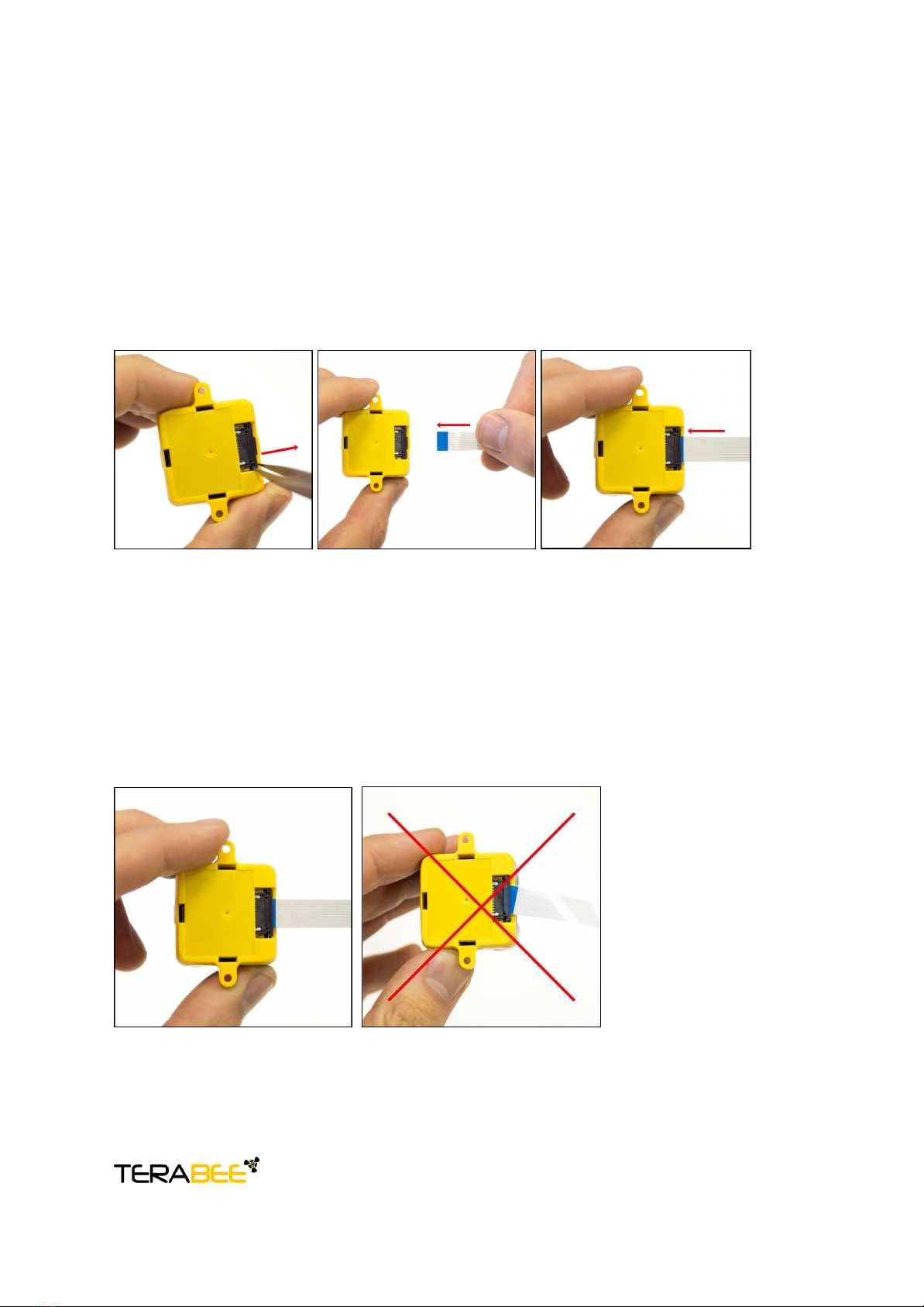
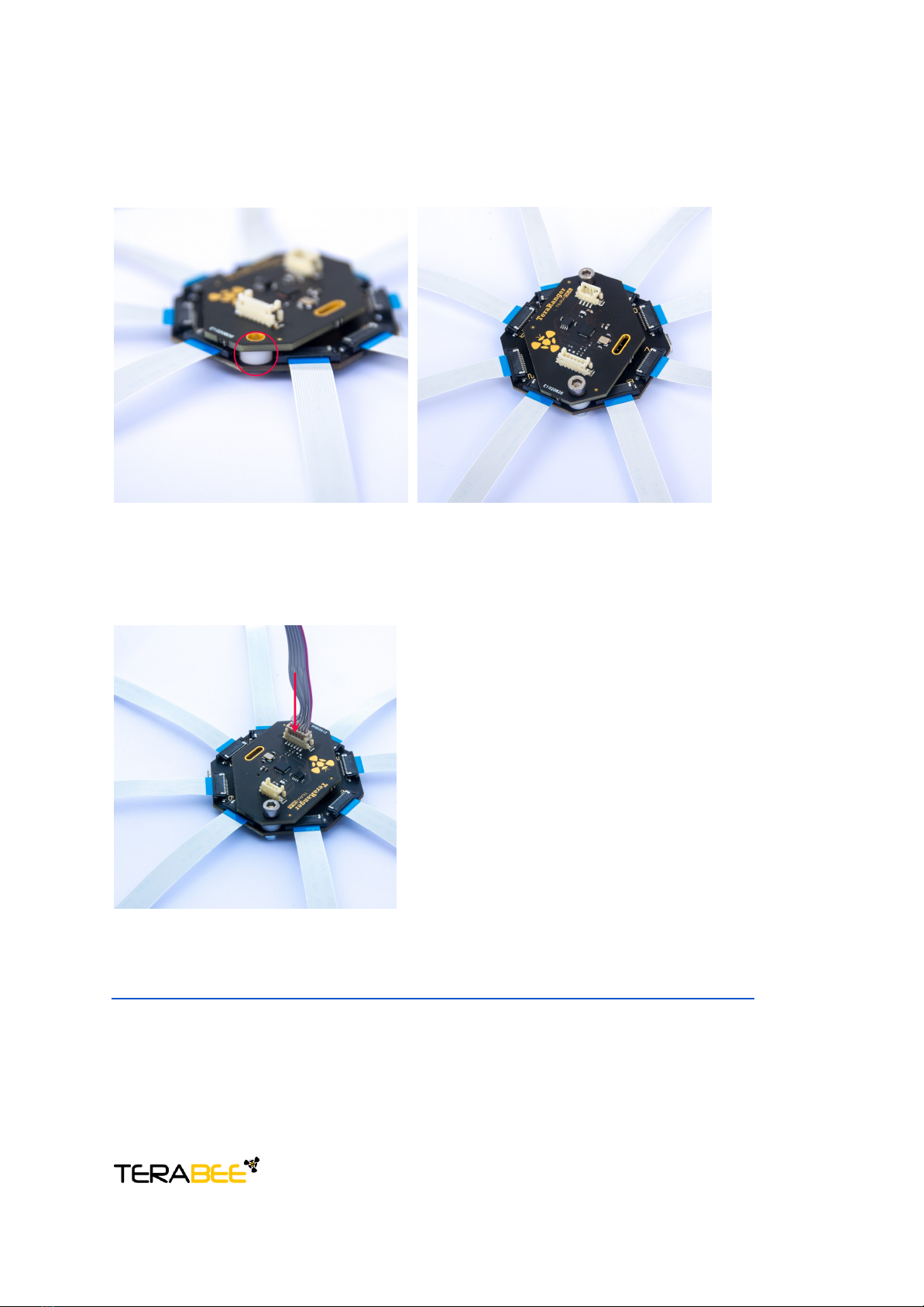
2.2 Handling during system assembly 6
2.3 Electrical characteristics 10
2.4 Additional interface for custom requirements 10
3 USB interface 11
3.1 Graphical User Interface 11
3.1.1 Basic Operation 11
3.1.1 Firmware Upgrade 12
3.2 Connecting the TeraRanger Hub Evo to a Host Computer 13
3.2.1 Prerequisites 13
3.2.2 Terminal Emulation Software 13
3.3 LEDs 15
4 UART interface 16
4.1 Pinout information 16
4.2 UART protocol information 17
4.3 Interface for visual signalization 18
5 Communication and Modes 20
5.1 Enable / Disable Hub Evo communication 21
5.2 Printout modes 21
5.2.1 Commands 21
5.2.2 Output format 22
5.3 Operating modes 23
5.3.1 Commands 23
5.4 Output-rate rate modes 23
5.4.1 Commands 24
5.5 Visual signalization 24
5.6 Internal Measurement Unit (IMU) options 25
5.6.1 Euler mode 25
5.6.2 Quaternion mode 26
5.6.3 Quaternions and linear acceleration 26
5.6.4 Commands 27
5.6.5 Output format 27
5.7 Command validation 30
.
Terabee Website:
90 Rue Henri Fabre Technical support:
01630, Saint-Genis-Pouilly Commercial:
2/31

1Introduction
The purpose of this document is to give guidelines for use and integration of the TeraRanger
Hub Evo board using a USB or UART communication interface. For streaming distance data
via UART, please see instructions on how to use the UART board in section 2.2. Instructions
on how to use Hub’s onboard Internal Measurement Unit (IMU) are available in section 5.6.
2Mechanical Integration
2.1Mechanical Design
Figure 1. TeraRanger Hub Evo external dimensions
TeraRanger Hub Evo external dimensions are illustrated in Figure 1. The board provides two
mounting holes, both designed for M3 screws. The straight distance between mounting
holes is 45.5mm. Figure 2 illustrates external dimensions of the UART board.
.
Terabee Website:
90 Rue Henri Fabre Technical support:
01630, Saint-Genis-Pouilly Commercial:
3/31

Figure 2. UART board external dimensions
2.1 Compatibility with TeraRanger Evo sensors
TeraRanger Evo is compatible with the following TeraRanger Evo sensors:
● Evo 60m
● Evo 3m
● Evo 600Hz
Up to 8 TeraRanger Evo distance sensors (of one type) can be connected to the Hub Evo
board for multi-axis, multi-sensor ranging operations. TeraRanger Evo sensors use a
two-part construction where the black colored optical sensor module simply clips to the
yellow colored backboard for power management and communication.
.
Terabee Website:
90 Rue Henri Fabre Technical support:
01630, Saint-Genis-Pouilly Commercial:
4/31

Figure 3. TeraRanger Evo Hub backboard
Please note that the Hub backboard is required for connecting Evo sensors to the Hub Evo
board (see Figure 3). External dimensions of the Hub backboard are illustrated in Figure 4:
Figure 4. Hub backboard external dimensions
.
Terabee Website:
90 Rue Henri Fabre Technical support:
01630, Saint-Genis-Pouilly Commercial:
5/31

2.2 Handling during system assembly
Please follow these simple steps showing how to connect 8 TeraRanger Evo sensors to the
TeraRanger Hub Evo.
Step 1. Connecting the cable to the sensor
Start by plugging the flat flex cables (FFC) to the sensor’s FFC connector.
Figure 5. Open, Insert, Close (sensor)
Note that each of the FFC connectors need to be manually opened and then closed when
connecting the Flex Cables as shown in Figure 5. For easier opening you can gently pull the
small locking ‘tabs’ on the sides of the connector before pulling the locking mechanism
down. You may find this easier with tweezers. The locking mechanism has to be pulled out
only a millimeter or less, not entirely! Note that, too much force can damage the sensors’
connector. Also, double check that the Flex Cable is plugged in straight so as to avoid a
potential short-circuit (Figure 6).
Figure 6. Left image - correct Right image - incorrect
When connecting the Flex Cable, make sure that the side with conductive tracks is facing
the sensor’s backboard (yellow part) as shown in Figure 7. Connecting the wrong side of the
.
Terabee Website:
90 Rue Henri Fabre Technical support:
01630, Saint-Genis-Pouilly Commercial:
6/31

cable can damage electronics on the hub and the sensor. Once the cable is positioned
inside the connector, close the connector by smoothly pushing the locking mechanism in.
Figure 7. Left image - correct Right image - incorrect
Step 2. Connecting the sensor to the Hub Evo
Follow the instructions above to connect the cables’ other end to the FFC connector on
TeraRanger Hub Evo board.
Figure 8. Open, Insert, Close (hub)
Step 3. Connecting all Evo sensors to the Hub Evo
Continue connecting the rest of the Evo sensors to the central Hub board (Figure 9).
.
Terabee Website:
90 Rue Henri Fabre Technical support:
01630, Saint-Genis-Pouilly Commercial:
7/31

Figure 9. TeraRanger Hub Evo with 8 sensors connected
Once fully assembled, the TeraRanger Hub Evo is ready for testing on your computer. Use
the micro USB cable (provided in the package) to connect the TeraRanger Hub Evo with a
host computer. Instructions on how to connect the system to a host computer or use a
Graphical User Interface are available in section 3.1 and 3.2.
Step 4. Connecting UART board to Hub Evo (optional)
To stream distance data from Hub Evo via UART, please follow these instructions.
Connect the UART board to Hub Evo’s FCI Bergstak 30 pin connector. Please make sure
you connect the UART board only after all sensors are connected to Hub Evo, as the UART
board allows very limited access to FFC connectors 1, 4, 5, 8 on Hub Evo (circled in red).
See Figure 10 for visual instructions.
Figure 10. Connecting the UART board to Hub Evo
.
Terabee Website:
90 Rue Henri Fabre Technical support:
01630, Saint-Genis-Pouilly Commercial:
8/31

Two spacers are provided in the package to ensure a more robust connection (Figure 11).
Place these between the Hub Evo and UART board covering the mounting holes. Please
note that you will need M3 screws (not provided) to enable mounting.
.
Figure 11. Mounting Hub Evo
Last but not least, connect the UART to open-ended cable to the DF13 6 pin connector
located on UART board and the other cable end to the host of your choice.
Figure 12. Connecting the UART cable
NB. Wiring instructions for Pixhawk autopilots are available here:
https://www.terabee.com/evo-connection-to-pixhawk-autopilots-teraranger-tower-evo/
The following aspects should also be taken into consideration when handling the
TeraRanger Hub Evo:
.
Terabee Website:
90 Rue Henri Fabre Technical support:
01630, Saint-Genis-Pouilly Commercial:
9/31

● TeraRanger Evo sensors and the UART boards should not be connected or
disconnected from the TeraRanger Hub Evo while it is powered
● Do not mount the TeraRanger Hub Evo onto hot surfaces or near other sources of heat
● Take all usual precautions for sensitive electronics such as maintaining a suitable
distance from strong electric and magnetic fields, strong radio emitters, etc.
● During assembly and integration, please observe all common ESD precautions
2.3 Electrical characteristics
DC electrical characteristics
TeraRanger Hub Evo is powered by an external power source, and can not be directly
powered by USB. The following table describes the amount of current and voltage needed to
make the TeraRanger Hub Evo work properly.
Parameter
Minimum
Typical
Maximum
Power supply
Voltage input (V)
Current consumption (mA @ 12V)
12
11
-
-
24
1100*
*Maximum current consumption with eight TeraRanger Evo connected and looking at long-range
targets or infinity in simultaneous mode. Drops significantly in sequential mode and varies with target
reflectivity and distance.
2.4 Additional interface for custom
requirements
An extension connector (FCI Bergstak 30 pin
connector) is available on the TeraRanger Hub Evo,
located in the center of the board. This connector
allows you to increase the number of communication
interfaces, power supplies and GPIOs, and provides the
possibility to modify functionality and performance of
Hub Evo. Please note that this additional interface is
used by the UAR board, hence custom communication
interfaces can be added only when the UART board is
not used.
communication interface development.
.
Terabee Website:
90 Rue Henri Fabre Technical support:
01630, Saint-Genis-Pouilly Commercial:
10/31

3 USB interface
3.1 Graphical User Interface
A free graphical user interface is available for Windows, providing an easy way to visualize
the data from all the TeraRanger Evo sensors connected to the TeraRanger Hub Evo. This
is useful for demonstration, testing purposes and checking some of the basic parameters of
the sensors. It also provides a way to easily upgrade the firmware running on the device,
should it be required.
3.1.1
Basic Operation
Make sure TeraRanger Hub Evo is connected to a USB port on your computer and to a
suitable power supply. Select File > Connect. You should immediately see distance readings
of TeraRanger Evo sensors displayed on the main chart.
Figure 15. Graphical User Interface
.
Terabee Website:
90 Rue Henri Fabre Technical support:
01630, Saint-Genis-Pouilly Commercial:
11/31

#
Display
Description
1
Measurement
Provides up to 8 distance values in millimeters. Sensors are
numbered as on the Hub Evo board. Example: TR Evo 3 will
stream distance data connected to connector Nr 3 on Hub Evo.
In case “-1” value is received, no sensor is connected or not able
to measure.
In case “+Inf” is received, the measurement is out of range.
In case “-Inf” is received, the measurement is below minimum
range.
2
Zoom
Modify scale of the main chart (#2) by just dragging the cursor to
the left or right. The zoom range is [2.00m ; 60.0m]
3
Main chart
Provides real-time preview of distance measurements streamed
from connected Evo sensors. The distance reading is visually
represented on the chart by a small segment.
4
Measurement
Mode
Switch between Sequential and Simultaneous mode. Please use
the Tower mode only when operating the TeraRanger Tower Evo
or the TeraRanger Evo Mini Array Kits
1
5
Update Rate
Select between six options of sensor measurement update rates
from a drop-down menu. Choose between Fixed (F) 50Hz, F
100Hz, F 250Hz, F 500Hz, F 600Hz or ASAP (As Soon As
Possible).
6
IMU
Enable or disable the option for Inertial Measurement Unit
readings. Three IMU modes are available for preview:
Euler mode, Quaternion mode, Quaternion and Linear
Acceleration mode.
7
LED
thresholds
Adjust between three levels of visual signalization provided to
discriminate three different ranges. LED signalization feature
available only through the use of UART board (optional
accessory).
3.1.1
Firmware Upgrade
The current firmware version on your TeraRanger Hub Evo can be found by selecting Help >
About in the GUI. It is possible to upgrade the firmware running on your device if a new
firmware version is made available by Terabee.
1 This Tower mode works best when sensors are positioned at an angle of minimum 45° between
each sensor in TeraRanger Evo Mini Array Kits 4 or 8 sensors
.
Terabee Website:
90 Rue Henri Fabre Technical support:
01630, Saint-Genis-Pouilly Commercial:
12/31

Please note the Upgrade Firmware feature is only supported on Windows 7, 8 and 10.
Please follow carefully the steps outlined below to avoid permanently disabling your device.
● Select File > Upgrade
Firmware
● You will be presented with a dialog window asking you to confirm your choice
Beyond this point, if you press ‘Yes’ it will not be possible to revert to the
firmware currently running on your TeraRanger Hub Evo! Press ‘No’ to cancel
and keep the current firmware or ‘Yes’ to continue
● Read the instructions in the dialog window that opens
● Press ‘Select FW’ and select the new firmware file with Windows File Explorer
● Press ‘Upgrade’ and wait until the operation finishes
● Close the Upgrade dialog window
3.2 Connecting the TeraRanger Hub Evo to a Host Computer
The TeraRanger Hub Evo can be easily connected to a Host Computer via the micro USB
cable provided in the package. The TeraRanger Hub Evo can interact as a virtual COM port,
and data can be streamed directly to terminal emulation software (Terabee advises to use
HTerm for Windows and CoolTerm for MacOS).
3.2.1
Prerequisites
For usage on Windows (7, 8) operating system, please download the Virtual COM Port driver
from http://www.st.com/en/development-tools/stsw-stm32102.html and follow the ”ReadMe
file” instructions given by the installer. After successful installation, unplug the interface
for a few seconds, and plug it back in. The virtual COM port should now be available on your
PC. Users of Windows 10 do not need to download this driver as the built in Windows driver
is recommended.
3.2.2 Terminal Emulation Software
In Windows you can also use any terminal emulation software of your choosing, however we
suggest you use HTerm (http://www.der-hammer.info/terminal/). Extract the downloaded zip
file to the folder of your choice, open it and double click on the “HTerm.exe” document.
Connect the TeraRanger Hub Evo to your computer and select the corresponding USB port
(click “R” button to refresh the port list). Select values for the following fields:
● Baud rate: 115200;
.
Terabee Website:
90 Rue Henri Fabre Technical support:
01630, Saint-Genis-Pouilly Commercial:
13/31

● Data Bits: 8;
● Parity: None;
● Stop Bits: 1.
For easier readings, select the “LF” option for “Newline at” tab. See Figure 13 for visual
instructions.
Figure 13. H-Term parameters
Once you have selected the USB port and required values, click on the “Connect” button.
Figure 14. Communication with H-Term
To communicate with the Hub Evo via the terminal emulation software, you need to send a
command in hexadecimal via the “Type” box. For this, select the “HEX” Type as illustrated in
the figure above. Figure 14 shows an example of the command which allows data to be
shown in TEXT mode. All commands are detailed in section 5.
In MacOS, Terabee advises the use of Coolterm for terminal emulation software.
.
Terabee Website:
90 Rue Henri Fabre Technical support:
01630, Saint-Genis-Pouilly Commercial:
14/31

3.3LEDs
In total, four LEDs are mounted on TeraRanger Hub Evo to give visual feedback on the
sensor performance. Table below lists the functionality of each LED:
LED color
Description
Hub Visual
PWR
(orange)
LED continuously on whenever
connected to a power supply
LED 0 (blue)
One blink for each TeraRanger Evo Hub
sensor detected by the Hub Evo.
Example: if 6 sensors are connected, the
blue LED will blink 6 times before sending
distance data.
LED 1
(green)
Continuous blinking indicates that
distance values are being sent
LED 2 (red)
Continuous blinking indicates an error
.
Terabee Website:
90 Rue Henri Fabre Technical support:
01630, Saint-Genis-Pouilly Commercial:
15/31

4 UART interface
4.1 Pinout information
The Hub Evo can be controlled through UART interface. This is possible thanks to a “UART
board” a clip-on accessory included in the Hub Evo package. See Figure 16 for visual
instructions.
Figure 16. UART board connection to Hub Evo
The UART board uses a single 6 pin Hirose DF13 connector for interfacing to the host
system. The mating connector is a Hirose DF13-6S-1.25C with crimping contacts
DF13-2630SCF (tin) or DF13-2630SCFA (gold). Please consider the mechanical stability of
the mated connectors and avoid any kind of excess force on the connector (during
installation and once integrated) and follow the recommendations in the Hirose DF13 series
datasheet (available here: https://www.hirose.com/product/en/products/DF13) to ensure a
reliable connection.
The table below provides an overview of the pinout for the DF13 connector:
Pin out and description (According to DF13 datasheet)
Pin
Designator
Description
1
NC
Not Connected
2
Rx(in)
UART receive input. 3.3V logic
3
Tx(out)
UART transmit output. 3.3V logic
4
NC
Not Connected
5
NC
Not Connected
6
GND
Interface ground
.
Terabee Website:
90 Rue Henri Fabre Technical support:
01630, Saint-Genis-Pouilly Commercial:
16/31

Figure 17. Pinout layout for UART
4.2UART protocol information
The UART communication for the TeraRanger Hub Evo uses a simple Modbus-like protocol.
The communication parameters are:
Baud Rate: 921600 baud
Data Bits: 8
Stop Bit(s): 1
Parity: None
HW Flow Control: None
.
Terabee Website:
90 Rue Henri Fabre Technical support:
01630, Saint-Genis-Pouilly Commercial:
17/31

4.3 Interface for visual signalization
UART board provides an interface to control an intelligent LED light source compatible with
WS2812B serial communication protocol. It allows you to drive up to four RGB LEDs through
a single wire provided that the LEDs sink current is kept within the power budget indicated in
the manual (ref. Section 2.3).
Three levels of signalization are provided to discriminate three different ranges (set with a
default value during manufacturing) as shown in the table below:
Detection
Distance
Color
No obstacle in range
Out of range
None
Obstacle detected in the range
>4m
Green
Obstacle detected in the range
2m to 4m
Orange
Close obstacle
0.5 to 2m
Red
New values can be programmed through the UART interface, offering the possibility of
customizing the LED triggering thresholds within the valid range of the Hub Evo. These
values can span from 0.5m to 8m in 0.1m increments. The upper value of the threshold
range cannot be higher than the lower value of the adjacent threshold range. Overlaps
between threshold ranges are checked by the Hub Evo and, if found, the Hub Evo responds
with a ‘Nack’ (Not acknowledged) signal. Once the thresholds system is operating, if all
sensors are detecting “out of range”, then all LEDs will be off. Whenever a threshold is
reached by one of the sensors, the LEDs will switch to the appropriate color and stay
continuously ‘on’ until a different threshold is activated.
Important Note: The LED signalization feature only provides an indicative proximity status
based on the closest Evo sensor to an obstacle or hazard and is provided as a useful aid
rather than a guaranteed fail-safe solution. You use this feature at your own risk.
Below 1 meter, some target surfaces (transparent or with low light reflectivity) can potentially
introduce false readings which could mean that the LED signalization is not based on the
closest sensor to an obstacle. However, this will only affect the LED signalization and not the
distance sensing capability.
.
Terabee Website:
90 Rue Henri Fabre Technical support:
01630, Saint-Genis-Pouilly Commercial:
18/31

Pinout and description:
Pin
Designator
Description
1
5V
+5V supply output
2
RFU
Do not connect, reserved for future use
3
DOUT
Control data output to drive four WS2812B LEDs
4
GND
Power supply and interface ground
Figure 18. WS2812B serial communication, pinout layout
.
Terabee Website:
90 Rue Henri Fabre Technical support:
01630, Saint-Genis-Pouilly Commercial:
19/31

5 Communication and Modes
The current Hub Evo firmware provides four parameters for optimization of Hub Evo
performance. The following parameters can be configured:
1. Printout modes
2. Operating modes
3. Update rate modes
4. IMU modes
Figure 19 illustrates the logic of available parameters on Hub Evo. Please note all
commands to be sent via terminal emulation software are in hexadecimal format.
Figure 19. TeraRanger Hub Evo modes
.
Terabee Website:
90 Rue Henri Fabre Technical support:
01630, Saint-Genis-Pouilly Commercial:
20/31
Other manuals for TeraRanger Evo
5
Table of contents
Other TeraBee Accessories manuals

TeraBee
TeraBee TeraRanger Multiflex User manual

TeraBee
TeraBee TeraRanger One User manual

TeraBee
TeraBee TeraRanger Evo Series User manual

TeraBee
TeraBee IND-TOF-1 User manual

TeraBee
TeraBee Follow-Me User manual

TeraBee
TeraBee IND-TOF-1 User manual

TeraBee
TeraBee TeraRanger Evo Thermal series User manual

TeraBee
TeraBee TeraRanger Evo Swipe Plus User manual

TeraBee
TeraBee TeraRanger Evo User manual

TeraBee
TeraBee TeraRanger Evo 64px User manual