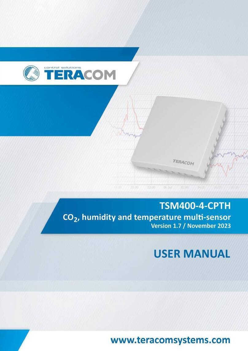
Teracom TSM400-4-CP User manual


TSM400-4-CP_R1.7 –November 2023 Page 2
1. Short description
TSM400-4-CP is a multi-parameter sensor that supports MODBUS RTU protocol over the RS-485
interface. The sensor measures barometric pressure and CO2concentration. The MODBUS device
integrates an advanced non-dispersive infrared sensing element (NDIR) for CO2measurements. The
measurement principle is based on the absorption of infra-red (IR) light with specific wavelengths by
CO2molecules. The CO2sensing element is temperature compensated for better accuracy. Self-
calibration is available for carbon dioxide measurements. It is done if the sensor is left in fresh (around
400 ppm CO2concentration) air.
The basic sensing element for barometric pressure is factory calibrated and it does not require any
lifetime recalibration.
The MODBUS CO2and pressure sensor TSM400-4-CP is housed in a slim plastic enclosure. The bottom
part of the enclosure is suitable for installation on standard flush-mounted/cavity wall boxes ø68mm,
with installation openings on 61 mm.
2. Features
•LED indicator for status of communication;
•Long-term stability based on digital signal processing;
•Self-calibration on fresh air for CO2measurements;
•RS-485 interface carrying up to 32 nodes;
•Changeable bitrate and other communication parameters;
•Firmware update via the interface.
3. Applications
•Indoor air quality (IAQ);
•CO2storage facilities leakage control;
•Smart ventilation systems;
•Restaurants and breweries CO2level monitoring.
4. Specifications
•Physical characteristics
Dimensions: 81 x 81 x 30mm
Weight: 66g
•Environmental limits
Operating temperature range: -20 to 60°C
Operating relative humidity range: 5 to 95% (non-condensing)
Storage temperature range: -20 to 60°C
Storage relative humidity range: 5 to 95% (non-condensing)
Ingress protection: IP20
•Power requirements
Operating voltage range (including -15/+20% according to IEC 62368-1): 4.5 to 26VDC
Current consumption: 25mA@5VDC (Peak: 150mA@5VDC)
•CO2measurements
Range: 400 to 5000ppm
Accuracy: ± (40ppm + 5%)
Resolution: 1ppm
Calibration: Manual/Automatic

TSM400-4-CP_R1.7 –November 2023 Page 3
•Pressure measurements
Range: 10 to 1200hPa
Accuracy (min): ±1.5% (25°C, 750hPa)
Accuracy (max): ±2.5% (-20°C to + 85°C, 300 to 1100hPa)
Resolution: 1hPa
•Interface
Response time ≤ 50ms
Master response time-out ≥ Response time + Answer time
The answer time depends on the number of bits and the baud rate
•Warranty
Warranty period: 3 years
5. Pinout
Pin
Description
UTP wires color
1-W
Not used
+5÷30V
Positive power supply
Brown/White Tracer
GND
Ground (negative) supply
Brown
A+
Line A+ (RS485+)
Blue/White Tracer
B-
Line B- (RS485-)
Blue
TERM
For termination, connect to B-
6. Installation
Two-Wire MODBUS definition according to modbus.org:
“A MODBUS solution over a serial line should implement a “Two-Wire” electrical interface in
accordance with EIA/TIA-485 standard. On such a “Two-Wire” topology, at any time one driver only
has the right to transmit. In fact, a third conductor must also interconnect all the devices of the bus -
the common.”
Attention:
For proper operation of the interface, terminators (120 ohms resistors) must be installed at both
ends of the bus. The device has a built-in 120 ohm resistor and to terminate the line, “B-“and
“TERM” must be shortened.
A daisy-chained (linear) topology for multiple sensors should be used. UTP/FTP cables are
mandatory for interconnection.

TSM400-4-CP_R1.7 –November 2023 Page 4
7. Installation tips
The location and the mounting position of the sensor have a direct effect on the accuracy of the
measurement. The tips below will ensure good measuring results:
•Sensor shall be installed about 1.2-1.4 m above the floor;
•To avoid solar radiation, the sensor should not be installed next to windows or directly in the
sunlight;
•Sensors shall be installed in a place with sufficient air circulation.
TSM400-4-CP sensor is intended for installation on a cavity wall box with 68mm diameter and 61
mm screw spacing.
8. Status indicator
The status of the device is shown by a single LED, located inside the box:
•If the LED blinks for a period of 1 second, the sensor works properly;
•If the LED blinks for a period of 3 seconds, there isn‘t communication with the controller;
•If the LED doesn‘t blink, there isn‘t a power supply.
9. CO2 Calibration
The device has the capability to automatically and manually calibrate carbon dioxide
measurements. It is advised by the sensor element's manufacturer to perform calibration on a
weekly basis.
The determination of whether the calibration is done manually or automatically depends on the
information stored in MB register with PDU address 2002.
The automatic self-calibration (ASC) feature ensures the device maintains the highest long-term
stability without requiring any manual actions from the user.
The algorithm for automatic self-calibration assumes that the sensor is exposed to an atmospheric
CO2 concentration of 400 ppm at least once per week.

TSM400-4-CP_R1.7 –November 2023 Page 5
Manual Calibration Procedure:
To manually calibrate the device, follow these steps:
•Place the device in a fresh air environment with a CO2 concentration of 400 ppm.
•While the sensor is in operation, press and hold the button.
•The “status” LED will start flashing once every second.
•After the 5th flash, the “status” LED will turn off and wait for the button to be released to
initiate calibration.
•Release the button.
•The calibration procedure will begin, indicated by the “status” LED staying continuously lit
for approximately 5 seconds.
•After a successful calibration, the “status” LED will flash 3 times in 1 second. In the case of a
failure, it will flash rapidly (15 times within a 3-second period).
•Following the calibration, the device will enter its standard operation mode.
10. Factory default settings
Disconnect the sensor from the bus (switch off the power supply).
Press and hold the “config” button. Don’t release the button, connecting the sensor to the bus
(switch on the power supply).
The “status” LED will be ON for 3 seconds and after this will flash for 7 seconds. After the 10-th
second the LED will be ON.
Release the button. The sensor will restart with factory default settings.
11. Firmware update
The firmware of the sensor can be updated with a Teracom controller which supports
MODBUS RTU or MBRTU-Update software. For more details, ask your dealer.

TSM400-4-CP_R1.7 –November 2023 Page 6
12. Modbus address table
Register name
R/W
FC
PDU
Address
(Decimal)
Logical
Address
(Decimal)
Offset
(Decimal)
Data size
Default
Valid values
RS-485 address
R/W
03/06
10
40011
40001
16-bit uns. integer
1
1-247
Baud rate*
R/W
03/06
11
40012
40001
16-bit uns. integer
19200
2400, 4800, 9600,
19200, 38400, 57600
Parity, data, stop bits *
R/W
03/06
12
40013
40001
16-bit uns. integer
1
1=E81, 2=O81, 3=N81
Data order
R/W
03/06
13
40014
40001
16-bit uns. integer
1
1=MSWF (MSW, LSW)
2=LSWF (LSW, MSW)
Device code
R
03
14
40015
40001
16-bit uns. integer
0x00C8
FW version
R
03
15
40016
40001
16-bit uns. integer
Vendor URL
R
03
18
40019
40001
64 bytes UTF-8
teracomsystems.com
Float test value (MSWF)
R
03
82
40083
40001
32-bit float
-9.9(0xC11E6666)
Float test value (LSWF)
R
03
84
40085
40001
32-bit float
-9.9(0xC11E6666)
Signed integer test value
R
03
86
40087
40001
16-bit sig. integer
-999(0xFC19)
Signed integer test value (MSWF)
R
03
87
40088
40001
32-bit sig. integer
-99999(0xFFFE7961)
Signed integer test value (LSWF)
R
03
89
40090
40001
32-bit sig. integer
-99999(0xFFFE7961)
Unsigned integer test value
R
03
91
40092
40001
16-bit uns. integer
999(0x03E7)
Unsigned integer test value (MSWF)
R
03
92
40093
40001
32-bit uns. integer
99999(0x0001869F)
Unsigned integer test value (LSWF)
R
03
94
40095
40001
32-bit uns. integer
99999(0x0001869F)
CO
2
, ppm
R
03
106
40107
40001
32-bit float
Pressure, hPa
R
03
108
40109
40001
32-bit float
CO
2
, ppm
R
03
206
40207
40001
32-bit float
Pressure, mmHg
R
03
208
40209
40001
32-bit float
CO
2
, ppm
R
03
603
40604
40001
16-bit uns. integer
Pressure, hPa
R
03
604
40605
40001
16-bit uns. integer
CO
2
, ppm
R
03
703
40704
40001
16-bit uns. integer
Pressure High-Word, mmHg x 100
R
03
704
40705
40001
16-bit uns. integer
Pressure Low-Word, mmHg x 100
R
03
705
40706
40001
16-bit uns. integer
Automatic self-calibration (ASC)
R/W
03/06
2002
42003
40001
16-bit uns. integer
0
0-disable, 1-enable
CO
2
multiplier **
R/W
03/16
2115
42116
40001
32-bit float
1.000
CO
2
offset **
R/W
03/16
2117
42118
40001
32-bit float
0.000
Pressure multiplier **
R/W
03/16
2119
42120
40001
32-bit float
1.000
Pressure hPa offset **
R/W
03/16
2121
42122
40001
32-bit float
0.000
Pressure mmHg offset **
R
03
2123
42124
40001
32-bit float
0.000
The shown logic decimal addresses are calculated with offsets 40001 (holding registers).
MSWF - Most significant word first - (bits 31 … 16), (bits 15 … 0); LSWF - Least significant word first - (bits 15 … 0), (bits 31 … 16);
PDU address - Actual address bytes used in a Modbus Protocol Data unit
When a floating-point value is not available, the returned value is “NaN” (e.g. in case of measurement error).
When a 16-bit signed integer value is not available, the returned value is “-32768” (e.g. in case of measurement error).
* The settings will take effect after restarting the device by power-off, power-on.
** Measured sensor values can be corrected by employing a multiplier and an offset.
The corrections are the results of the following calculations:
Corrected CO2= Measured CO2× CO2Multiplier + CO2Offset
Corrected Pressure (hPa) = Measured Pressure (hPa) × Pressure Multiplier + Pressure Offset (hPa)
Using a multiplier and an offset allows precise adjustments to the sensor readings, ensuring accurate CO2and pressure values.
After obtaining the corrected pressure in hPa, it can then be converted to mmHg.
13. Recycling
Recycle all applicable material.
Do not dispose of with regular household refuse.
Table of contents
Other Teracom Security Sensor manuals
Popular Security Sensor manuals by other brands
Rielta
Rielta Ladoga MK-RK version 2 installation guide

PCB Piezotronics
PCB Piezotronics ICP 113A22 Installation and operating manual

Wenglor
Wenglor P1KK008 operating instructions
Alula
Alula RE307 manual

STEINEL PROFESSIONAL
STEINEL PROFESSIONAL IR 180 Information
Sun Microsystems
Sun Microsystems FI316 user manual
