Teral VKN Series User manual

Coolant Pump
Instruction Manual
VKN. VKP. VKS. VKR. Series

1
INSTRAUCTION
Thank you for purchasing our Coolant Pump.
We are proud of the quality and ease in handling as its primary features, the coolant pump is extremely
sturdy and simple in construction, both mechanically and electrically. In order to avoid unexpected
problems caused by mishandling, and to obtain top operating performance from the pump, we
recommend that this instruction manual be read carefully and used as a constant reference as a
guarantee of maximum efficiency.
Acceptance checks ---------------------------------------------------------
Before installation, check the coolant pump for the following.
1) Check to see if the product you received is the one you ordered.
(PUMP TYPE, OUTPUT, VOLTAGE, FREQUENCY, etc.)
2) See if any portion has been damaged during transportion.
If any defective points are defected, contact your dealer.
Specifications ----------------------------------------------------------------
Refer to the nameplate for the coolant pump's head, flow rate, frequency, voltage, current, etc.
Other specifications are described below.
Refer pump HEAD, QUANTITY, FREQUENCY, VOLTAGE and CURRENT to the nameplate.
Another specifications are as follows.
1.FLUID USED
Coolant pump is designed to use for cutting oil. Don't use water andspecial fluid such as printing fluid,
acid fluid, etc.
2.VISCOSITY OF FLUIDS USED
As viscosity of the fluid used in the pump increases the work load carried by the motor rises. The
motor will labor under an excessive load when viscosity of the fluid in the pump rises beyond the
viscosity range shown below. Use of fluid with viscosity exceeding these specifications will shorten
the overall operating life of the pump or even cause the pump motor to burnout. The viscosity range
of fluid appropriate for a pump is determined by the rated output of the motor, and motor output varies
depending on its type and frequency.
2
See the table unit : ㎟/s , ( No. 1 Red wood second )
Frequency 50 Hz 60 Hz
VKP045L to 115A 200 ( 800 ) 75 ( 300 )
VKP045A(L) to 115A
VKP075T~095T 300 ( 1200 ) 150 ( 600 )
VKN, VKP055H to 095H 37.5 ( 150 ) 37.5 ( 150 )
VKS Series
( Without VKS123AB
VKS152AC ) 75 ( 150 ) 75 ( 300 )
VKS123 AB ・152 AC 150 ( 600 ) 125 ( 500 )
VKR 131 AD 2.5 ( 32 ) 2.5 ( 32 )
VKR 092 AB to 122AD 75 ( 300 ) 75 ( 300 )
Note: The unit used to designate viscosity is the kinematic viscosity.
Since fluid viscosity dependents on the ambient temperature, always check fluid viscosity with
the lowest possible temperature.
3. MAX. SUCTION PIPE LENGTH (VKN SERIES)
Allowable pipe length for selt-priming operation is within 0.7 meter.
(VKN085A, VKN085H and VKN095H: Max. 0.6 m)
Note: Max. suction pipe length is inversely proportional to the square of diameter if it differs from
standard diameter.
Installation --------------------------------------------------------------------
1. Coolant pump is for indoor use, only,
Don't use it outdoor.
2. Install the pump in a location to allow for inspection and maintenance work. The place where the
pump is installed should be well ventilated and free of fluid spills.
3. Install the pump on a horizontal flat surface.
4. nstall pump where the ambient temperature is between -20°C to +40°C.
(VKN Series and VKS152AC: from 0°C to +40°C)
5.Two mounting bolts, placed diagonally opposite each other, are sufficient for installation. But, because
installation is easier if four bolts are available, four have been provided.

3
6. Install the pump upright, vertical to the surface of the water, as shown in the drawing on the left. Do
not install it below the surface of the water, or parallel to or at an oblique angle to the water's surface.
7. The VKN series are designed so that the possible fluid leaking through the shaft seal is drained to
protect the motor, this occurs when the shaft seal (mechanical seal) is worn or damaged. Proper
steps must be taken in advance for drainage of this leakage back to the oil or fluid tank.
8. In case of the immersion type (VKS, VKP, VKR, series) it is necessary to make the hole for the oil
reservoir slightly larger in diameter than the outside diameter of the pump section.
9. The VKP115A, VKP075J, 085J, 095J, VKR series and VKS series both have a suction port at the
bottom. The distance to the bottom of the tank should be larger than the value shown in the outline.
Piping --------------------------------------------------------------------------
1. The piping should be as short as possible, with minimum bends, elbows, joints and valves. Be sure to
use pipes of the standard diameters.
2. The piping should be supported making sure that the weights of the inlet and outlet pipes are not
applied to the pump body.
3. Avoid using unreasonable force when connecting the inlet and outlet ports of the pump to the piping.
Otherwise, the joints of the pump may be damaged.
4. The joints should be treated with seal tape or fluid packing to prevent leakage of water and air. In the
VKN series, special care should be taken with regard to air leaks through the suction pipe, for it
reduces the water flow or the pump may not prime itself.
5. Use an oil reservoir with the largest possible capacity. The capacity should be more than "3 times" the
flow of the pump per minute. If the capacity is too small, it can result in increase in fluid temperature.
Damage to the pump may be caused by metal chips or air bubbles which reduces the pump capacity.
6. Make certain that the pump and reservoir is free from metal chips, dust and other foreign matter, prior
to start up. It is recommended that an overhaul device (3 steps or more) and a filter be installed. In the
VKN series (self - priming type), entry of metal chips in the pump will damage the shaft seal
(mechanical seal).
7. If there is any possibility of water hammering, a pressure buffer (accumulator, etc.) needs to be
installed.
8. VKN series ( self - priming type)
1 The suction pipe should be up to 0.7 m in length including horizontal sections.
(VKN085A,VKN085H and VKN095H: Max. 0.6 m)
If it becomes necessary to extend the length of the pipe, attach a check valve having a small head
loss to the end of the pipe.

4
2 The end of the suction pipe should be immersed in the fluid to the depth ("L" shown in the figure)
and spaced apart from the wall of the oil tank (“B" shown in the figure).
When the end of the pipe is positioned too high or it is too close to the wall, air is sucked up which
causes failure of fluid pumping-up, vibration and noise, etc.
3 The end of the suction pipe should be sufficiently spaced apart from the bottom of the oil tank ("Lb"
shown in the figure), otherwise, it can result in failure of pumping-up and entry of metal chips.
JEM Dimension Length of suction pipe: Max. 0.7m
(VKN085A, VKN085H and VKN095H: Max. 0.6 m)
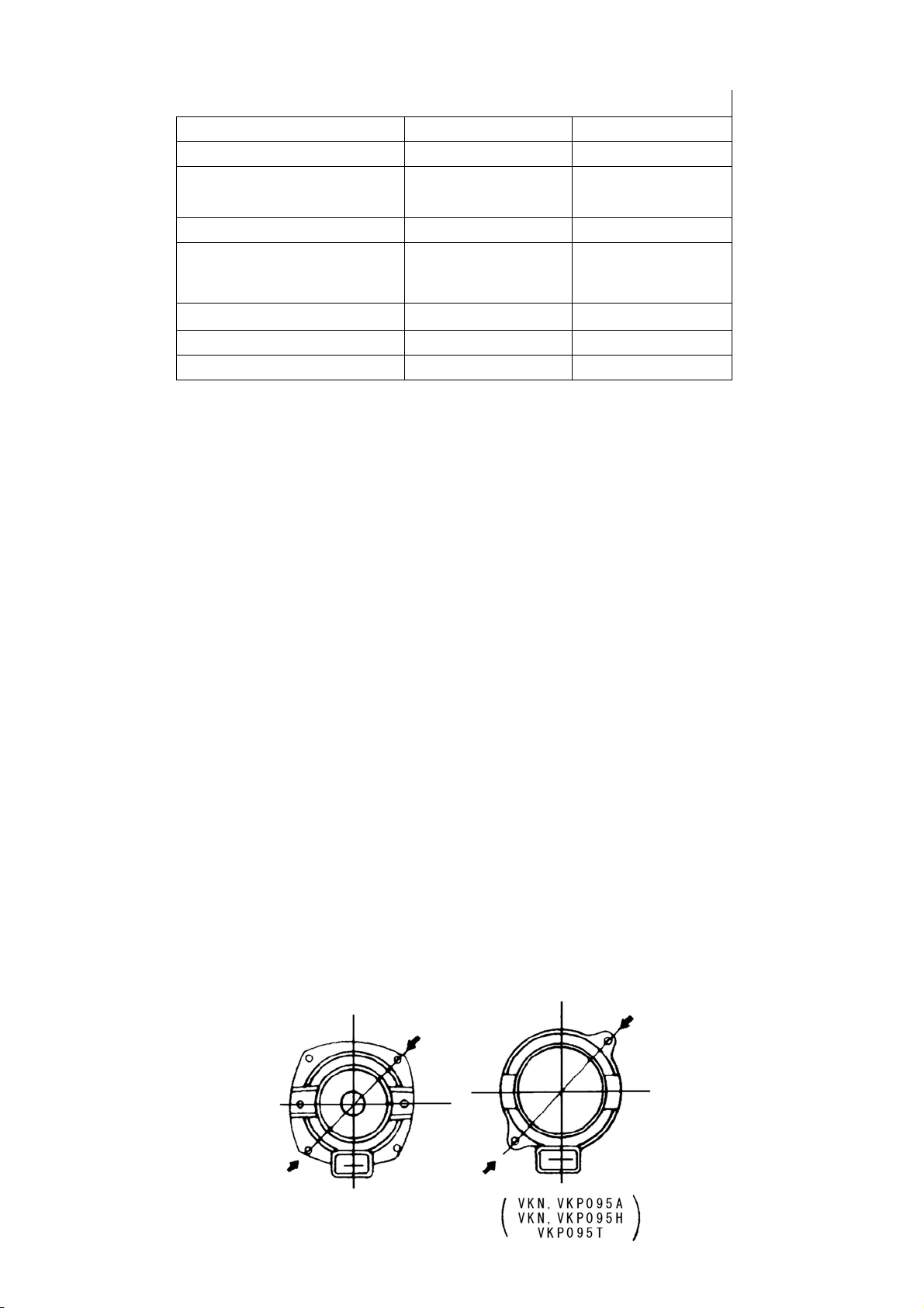
9. In case of VKN045Ato 095A, VKN055H to VKN095H, the position of inlet and outlet can be adjusted
60° at a time by rearranging the pump casing and the bottom plate.
Oil Tank ------------------------------------------------------------------------
1. Assure that the capacity of the oil tank is sufficiently large. If its capacity is less than it should be,
metal chips and other contaminates may enter the pump and probably accumulate more quickly,
thereby causing the flow to decrease. Install overflow equipment for more than a three-shift system
or an adequate filter to prevent the pump from sucking in metal chips and other foreign matter.
The pump of the water-immersion type (VKP), is designed for installing a filter.
Wiring --------------------------------------------------------------------------
1. Wiring must conform to the electrical equipment technical standards and the extension wiring
standards of electric codes.
2. Terminals should be connected correctly to the power source as shown at right (standard type)
3. The motor should be grounded to prevent any possibility of leaks, or shock.
5
4. It is recommended to use a thermal relay for protection of the motor against damage due to
overload, or a magnetic motor starter with thermal overloads sized for the motor.
5. The terminal box can be relocated by adjusting the frame of the motor according to the installation
place.
VKN045A – 085A
Series Adjustment angle
VKN・VKP045A to 085A(T)
VKP075J to 085J 180°opposite side
VKN・VKP095A(T) to 115A
VKP095J
VKP055H to 095H
VKS123AB・114AA・154AC
VKR series
90°at a time
VKS152AC・134AB – 144AC 120°at a time
6. The lead-in port of the terminal box can be turned 90° in any direction by adjusting the frame of the
motor according to the installation place.
When changing the installation direction, care should be taken to prevent entry of metal chips and
fluid through the connector, gland, etc.
Operation ---------------------------------------------------------------------
1. Preparation for operation
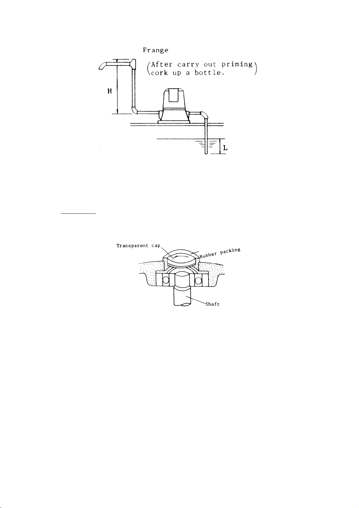
1. When the VKN series (self-priming type) are to be started for the first time after installation or
operated again after they have been left unused for a long time, be sure to carry out priming
with fluid.
Never operate the pump without priming, as it damages the shaft seal (mechanical seal).
2. Priming should be carried out until the air in the pump is completely removed through the outlet
(no air at the end of suction pipe).
When the priming is not completed and the pump is operated, the fluid cannot be pumped up
or the shaft seal may be damaged.Also, when the height from the outlet of the pump to the
priming fluid injection port ("H" shown in the figure) is lower than the length (“L" shown in the
figure) of the suction pipe immersed in the fluid, the priming fluid may not be fed sufficiently to
the pump. In such a case, an air vent should be provided on the suction pipe or the priming
fluid injection port should be positioned higher.
6
3. The VKP (immersion type) and VKS (high-pressure immersion type) series require no priming.
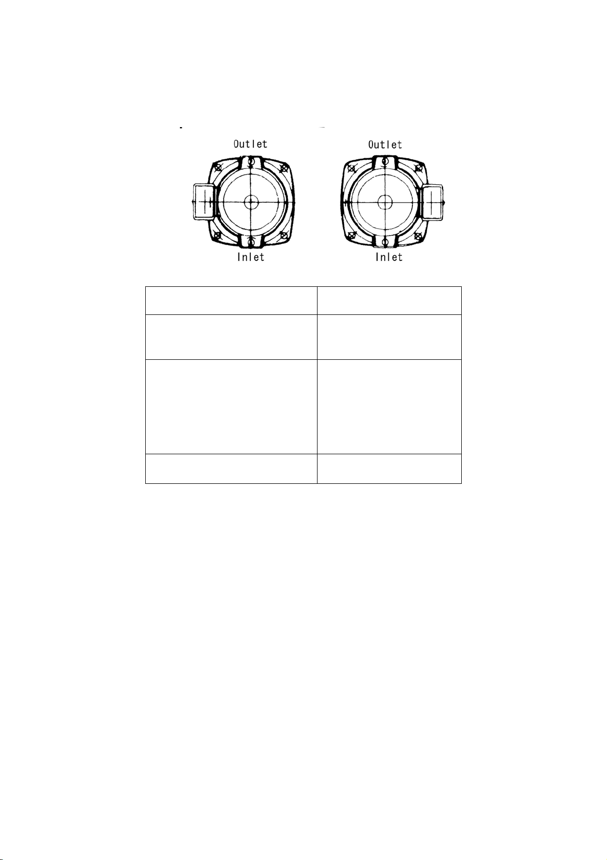
2. Direction of rotation
1. The motor must rotate to the left when viewed from above. Atransparent cap is provided on
top of the motor for easy inspection. The direction of rotation must be in the same direction as
indicated by the arrow on this transparent cap.
IMPORTANT
Notes: (The VKS 123AB, 152AC and VKR 131AD series are designed for right rotation.
Transparent cap is not provided with the VKN/VKP 095A(T), 115A, VKR series and VKS
series. The rotating direction can be checked by the rotation of the external fan.)
2. Check the pump for unusual current, vibration and noise. If any trouble is apparent, take
necessary steps referring to the "Troubleshooting".
3. Construction
1. Coolant pump is a centrifugal pump. The amount of flow can be adjusted as desired by
opening and closing the outlet valve. The motor is free from overload even when the valve is
closed. However, if the valve is left closed for many hours, the fluid in the pump increases in
temperature. In such a case, allow a little flow (more than 100 cc/min) or stop the motor if it is
not used.
When the fluid temperature is too high, it reduces the life of the motor or damages the shaft
seal (VKN series).
2. When the fluid level is too low, air may be sucked into VKP, VKR and VKS type pumps, making
pumping impossible. Therefore, the recommend marginal and minimum fluid levels are
marked on the outline drawing on the left and on all immersion type pumps.
(Pump VKP115A, and VKS are an exception to the above statements, because its delivery
inlet faces downward, while the inlets of other pumps face upwards.)

7
★Marginal fluid level: The level at which the quantity of fluid is almost equal to the rated value,
assuming that no air is being sucked into the delivery inlet.
★Minimum fluid level: The level at which the quantity of fluid is about 1/2 the rated value,
assuming that air is being sucked into the delivery inlet, but not in a quantity large enough
to affect pump operations.
★Maximum fluid level: The level 10 mm to 20 mm below the oil thrower, which is attached to
the shaft between the pump and motor to prevent oil from flowing into the motor.
The above fluid levels were obtained with cutting oil that had a viscosity of about 2.5 ㎟/s (32R").
Such levels vary according to the viscosity of the fluid used. They have to be raised when fluid
viscosity is higher than the viscosity of water, or 2.5 ㎟/s (32R").
A fluid with a viscosity lower than the maximum value should be used, since a highly viscous fluid
requires a large force to circulate it.
And, the use of large forces to circulate fluids can cause motors to overheat.
In winter, special attention should be given to fluid viscosity. For safety reasons, the oil in the oil tank
should be at as high a level as possible.
In case of power failure during operation, be sure to turn OFF the power switch.

8
Type Marginal fluid
level ( LK ) Minimum fluid
level ( LM )
VKP 035L 105 mm 115 mm
VKP 045L
VKP 045A
VKP055A
VKP055H
100 110
VKP 065A
VKP065H 90 100
VKP 075A (T)
VKP 075H 105 130
VKP 085A (T)
VKP 085H 165 190
VKP 095A(T)
VKP 095H 160 200
VKP 115A 220 -
VKS 123AB 240 -
VKS 152AC 180 -
VKS 114AA
VKS 134AB
VKS 144AC
VKS 154AC
190 -
VKR 092AB
VKR 112AC
VKR 122AD 150 -
VKR 131AD 165 -

9
Maintenance and Inspection----------------------------------------------
1. Routine inspection
At the start of operation of the pump, check it for unusual vibration and noise.
2. Periodical inspection
Clean the exterior of the coolant pump to remove dust and oil. Clean the oil tank periodically.
Notes that deposits of metal chips in the oil tank can result in damage to the pump.
3. Bearings
Ball bearings sealed in grease, with a semipermanent operating life, are used in this pump,
requiring very little need for maintenance. In case the ball bearings develop trouble, immediately
replace them with new ones. Bearing numbers for each type pump are given on the Nameplate.
4. Mechanical seal
The mechanical seal is designed, so the possibility of mechanical damage is reduced to a
minimum, thereby, contributing to an extremely long usable life. Damage to the mechanical seal is
most often caused by the entry of dust and other foreign matter which finds its way into the seal.
The following indications warn of damage to the mechanical seal, if anyone of these troubles
occur, replace the defective seal with a new one. When installing a new mechanical seal, assure
that the positioning of the metal retainer is as shown in the adjacent photo.
Troubles
Starting: Self-suction time is long.
In the worst case, self-suction stops completely
Operation: The amount of flow is reduce;
oil cannot be pumped up.
Stopping: Liquid leaks through drain hole.
VKN045~095A VKN115A
5. Maintenance of oil seal
The VKS 152AC is provided with an oil seal to prevent entry of liquid into the bearing. The oil seal
should be replaced with new one at the time of replacement of the bearing.

10
WARNING!
This coolant pump is designed to operate indoors, water or liquid must not be sprayed directly onto the
motor of the pump or terminal box.
This coolant pump is onlya component, it must be installed ina machine or part of a machinery which
meets the terms of the Machine directive 89/392/EEC. Commission will not occur until the end
product or machinery conforms with the guidelines in EN60204-1.

11
The following shows the constructions of typical types of the series.
No. Name No. Name
1 Frame 15 Pump stem
2 Shaft 16 Mechanical seal
3 Rotor 17 Base
4 Stator 18 Oil thrower
5 End shield 19 Terminal box
6 Bearing not drive
side 20 Earth terminal
7 Bearing drive side 21 Loose lead
8 Spring washer 22 Terminal board
9 Inspection
window 23 Shaft sleeve
10 End cover 24 External fan
11 Impeller 25 Fan cover
12 Spiral casing 26 Liner ring
13 Casing 27 Guide vane
14 Adjustment
washer
Note) 1. 035L, 04SL: Without terminal box. Cab-tyre cable is provided.
2. VKN/VKP 095A(T), 095H, 115A, VKS 123AB, 114AA, 133AB, VKR series: Steel plate,
totally-enclosed, outer-fan type motor.

12
Troubleshooting -------------------------------------------------------------
Troubles Possible cause Remedy
Disconnection of cables or
loose connection. Check cables and
connections.
Blown fuse.
Tripping of thermal relay Replace fuse.
Check thermal relay.
No operating
sound.
Disconnection of stator
winding Send to factory for repair, on
repair station.
Voltage too low. Raise voltage to level
specification plate
Disconnection of cables or
loose connection. Check cables and
connections.
Blown fuse.
Tripping of thermal relay Replace fuse.
Check thermal relay.
Disconnection of stator
winding Send to factory for repair.
Bearings worn out so stator
and rotor are in contact. Change bearings.
Motor does not
turn
Humming noise.
Deposits of foreign matter on
impeller. Remove foreign matter.
Voltage unbalanced. Check voltage transformer
and its circuit.
Excessive or insufficient
voltage. Correct power source
voltage.
Open stator winding. Send to factory for repair.
Motor turns Motor excessively
heated.
Bearings worn out so stator
and rotor are in contact. Change bearings.

13
Troubles Possible cause Remedy
No priming. Carry out priming.
Fluid level lower than suction
inlet. Raise fluid level.
Air being sucked in from
suction pipe. Check suction pipe for air
leaks.
Noting pumped
up.
Mechanical seal worn out. Change mechanical seal.
Slight amount of air being
sucked in from suction pipe. Check suction pipe for air
leaks.
Too many air bubbles
contained in fluid used.
Eliminate bubbles or stop
possible entrance of air into
fluid.
Motor rotation in reverse. Reposition 2 of 3 terminals.
Large loss of piping. Check piping.
Piping is loaded with foreign
matter. Remove foreign matter, and
check connections.
Low pump flow.
Mechanical seal worn out. Change mechanical seal.
Bearings worn out. Change bearings.
Excessive
vibration or noise. Motor in single-phase instead
of three-phase operation. Check for opened circuit.
Motor turns
Water hammering Generation of hammering at
sudden closing of piping. Mount pressure buffer near
valve.
★For repair work and necessary replacement parts,contact the Teral Inc. representative or distributor
in your area.
Always furnish us with the following facts:
(1) Type of pump (shown on specification plate)
(2) Serial No. of pump.
(3) Trouble spots and condition of damage.
(4) Names and number of parts that require changing.
(5) Length of time during which pump has been in activity.

14
Product warranty ------------------------------------------------------------
The product is covered under warranty for one year from the date of delivery to the customer's specified
destination. This product warranty is void, however, under any of the following conditions.
(1) Damage due to mishandling or misuse by the user.
(2) Damage due to causes not associated with the product.
(3) Unauthorized repair or modification.
(4) Circumstances beyond the supplier's control, such as natured or other disasters.
This warranty is limited to the supplied product only and does not apply to any damages to person or
property resulting from product failure.

Head Office
230, Moriwake, Miyuki-cho, Fukuyama-city, Hiroshima, 720-0003, Japan
Tel.+81-84-955-1111 Fax.+81-84-955-5777
www.teral.net
0000 00
E‑IMN‑00203‑000‑T
This manual suits for next models
30
Other Teral Water Pump manuals

Teral
Teral Patron SP-20 User manual

Teral
Teral NSVM Series Installation instructions

Teral
Teral MC5 User manual

Teral
Teral SJS-e User manual

Teral
Teral VFZ Series User manual

Teral
Teral LHW-e User manual

Teral
Teral VKD-e Series User manual

Teral
Teral Patron SP-40 User manual

Teral
Teral S User manual

Teral
Teral VKA Series User manual

Teral
Teral LVS-e Series User manual

Teral
Teral PL Series User manual

Teral
Teral LPWE-GS User manual

Teral
Teral LS2 User manual

Teral
Teral ASVM Series User manual

Teral
Teral MSU User manual

Teral
Teral Patron SP-10 User manual

Teral
Teral VKN-e Series User manual

Teral
Teral SP3-e User manual

Teral
Teral VKA-e User manual


