Teral VKD-e Series User manual

Model : VKD-e
Coolant Pump
Coolant Pump
Instruction Manual
Original Instructions

I
Limited warranties
1. In the event of failure or breakage under proper use of the product during the warranty period,
equipment supplied by Teral Inc. shall be repaired or replaced free of charge within the scope of the
relevant part, provided that such failure or breakage is attributable to inadequacy of the design or
workmanship of the equipment.
The warranty period of this product shall be one year after the date of delivery.
2. The warranty mentioned in the above clause shall be only the mechanical warranty of the defective
part, and shall not cover any expenses or other damage arising from the failure or breakage.
3. In the event of the following failures and breakage, the costs of the repairs shall be borne by the user.
(1) Failures and breakage attributable to equipment that was not delivered by Teral Inc.
(2) Failures and breakage after the expiration of the warranty period
(3) Failures and breakage caused by disasters or force majeure, such as fire, acts of God or
earthquakes
(4) Failures and breakage resulting from repairs or modifications made without the consent of Teral
Inc.
(5) Failures and breakage when parts other than those designated by Teral Inc. are used
(6) Failures and breakage caused by use or storage outside the specification range
4. Teral Inc. shall not be liable for the damage caused by incorrect or reckless use of the pump. Cost and
expenses incurred for sending engineer(s) in such a case shall be borne by the user.
5. If the cause of the failure is unclear, necessary actions shall be determined through mutual
consultation.
<Chargeable repair>
Investigation and repair work after the warranty period shall become chargeable. The repair and
investigation of the above-mentioned failures outside the warranty range shall be undertaken by Teral Inc.,
even though outside the warranty period.

II
Purpose of this manual
The purpose of this manual is to provide the user with detailed information necessary to properly operate,
maintain and inspect the pump. This product may cause an unexpected accident when handed incorrectly.
Please use the product correctly according to this instruction manual.
This manual contains the following information and is intended for persons experienced in the operation of
pumps, or for those who have been trained by such experienced operators. Only qualified personnel such
as licensed electrical engineers are allowed to carry out the electrical wiring work.
Contents
Page
Limited warranties .......................................................................................................................................... I
Purpose of this manual.................................................................................................................................. II
Contents ........................................................................................................................................................ II
1. Safety precautions...............................................................................................................................1-1
1.1 Types and meanings of warning terms and graphic symbols.....................................................1-1
1.2 Safety precautions.......................................................................................................................1-1
1.3 Location of warning labels and caution labels.............................................................................1-4
2. Configuration and overview of the pump.............................................................................................2-1
2.1 Part names and functions............................................................................................................2-1
2.2 Type description ..........................................................................................................................2-1
2.3 Standard specifications ...............................................................................................................2-2
2.4 Nameplate entries.......................................................................................................................2-3
2.5 Specification table .......................................................................................................................2-3
2.6 Dimensional outline drawing and dimensions table....................................................................2-4
2.7 Internal structural drawing...........................................................................................................2-5
3. Transportation, conveyance, storage and installation.........................................................................3-1
3.1 Precautions for transportation, moving and storing the pump ....................................................3-1
3.2 Before using the pump................................................................................................................3-1
3.3 Precautions for installation..........................................................................................................3-2
3.4 Precautions for piping work.........................................................................................................3-4
3.5 Precautions for wiring work.........................................................................................................3-4
4. Operation.............................................................................................................................................4-1
4.1 Check items before test operation ..............................................................................................4-1
4.1.1 Check items related to the electrical system.......................................................................4-1
4.1.2 Check items related to the pump.........................................................................................4-1
4.2 Running the pump (test operation)..............................................................................................4-2
5. Maintenance and inspection ...............................................................................................................5-1
5.1 Precautions for maintenance and inspection..............................................................................5-1
5.2 Daily check..................................................................................................................................5-2
5.3 Periodic inspection......................................................................................................................5-2
6. Troubleshooting...................................................................................................................................6-1
7. After-sales service...............................................................................................................................7-1
8. Disposal...............................................................................................................................................8-1
8.1 Precautions for disposal..............................................................................................................8-1

1-1
1. Safety precautions
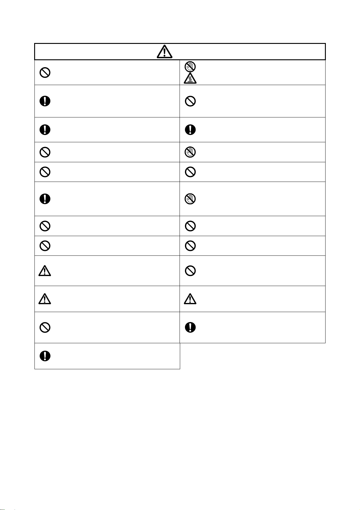
1.1 Types and meanings of warning terms and graphic symbols
This instruction manual divides precautions into the following four categories according to the
level of hazards (or the severity of the accident). In addition, prohibited or mandatory actions as
well as cautions are indicated with a graphic symbol.
Be sure to understand the meanings of the following terms and comply with the content
(instructions) of the instruction manual.
Explanation of the warning terms Explanation of the graphic symbols
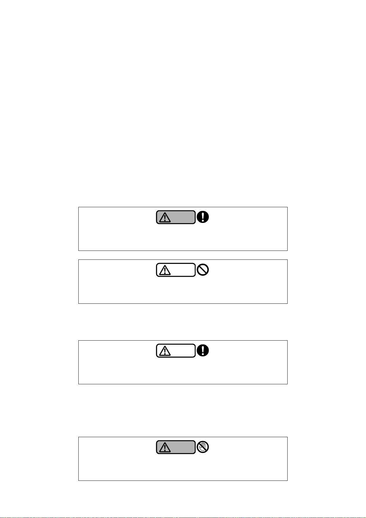
Warning Term Meaning
Danger
Indicates an imminently hazardous
situation. Failure to observe this will result
in death or serious injury. Don’ts Do not touch Do not
disassemble Do not touch
with wet
hand
Do not
expose to
water
These graphic symbols indicate prohibited actions
(that must not be done).
Warning
Indicates a potentially hazardous
situation. Failure to observe this will result
in death or serious injury.
Do’s
This graphic symbol indicates mandatory
actions (that must be done).
Caution
Indicates a potentially hazardous
situation. Failure to observe this will result
in minor or moderate injury or property
damage. Caution Electric
shock
hazard
Rotation
hazard Hot surface
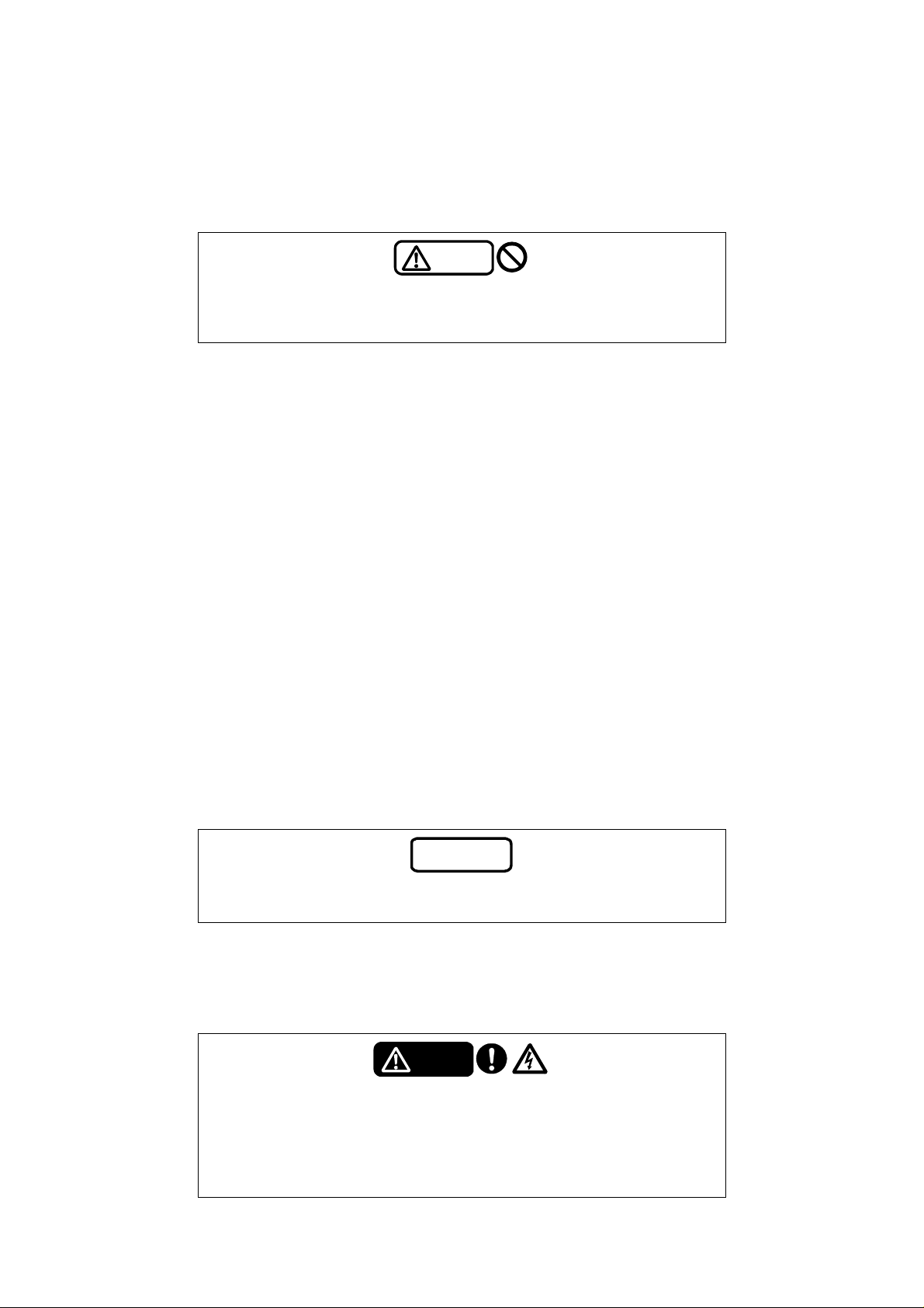
Note
Indicates information that is in particular
to be noted or emphasized. These graphic symbols indicate existing hazards to
beware of.
1.2 Safety precautions
Danger
Do not touch any energized parts after turning on the main power.
Doing so may cause electric shock leading to death because high voltage is applied to the energized part.
Do not use the product in any explosive atmosphere.
Doing so may cause an injury and fire.
Warning
Properly move the unit according to lifting
instructions.
Otherwise, the unit may fall, resulting in injury and/or damage.
Do not use the pump or perform any work with the
pump lifted up.
Otherwise, the unit may fall, resulting in injury and/or
damage.
Only those who are authorized by the site manager
are allowed to operate the pump.
Operation by unskilled personnel may lead to an unforeseen
accident.
Installation, maintenance, and inspection must
only be carried out by personnel who have been
trained to handle the pump.
Operation by unskilled personnel may lead to an unforeseen
accident.
Only qualified personnel, such as licensed electrical
engineers, are allowed to carry out any electric
work.
Otherwise, it may lead to an electric shock, fire, failures,
and/or other problems.
Use high-quality wiring equipment and devices,
and carry out wiring work safely and securely
according to the technical standards for electrical
facilities, as well as the indoor wiring regulations.
Otherwise, it may lead to an electric shock, fire, and/or other
problems.
Do not connect the ground wire to a gas pipe or
water pipe.
Such a connection is illegal and leads to an electric shock,
explosion and/or fire.
Securely install the ground wire and ensure to
carry out grounding work.
Otherwise, it may lead to an electric leak and/or electric
shock.
Do not operate the pump when its action or parts
are abnormal.
Otherwise, it may lead to injury, failures and/or various
accidents.
Wiring must be performed reliably according to the
connection diagram within the terminal box and
the instruction manual.
Incorrect wiring may cause fire, electric shock and other
accidents.

1-2
Warning
Be sure to keep the terminal box cover installed
during operation of the pump.
Otherwise, it may lead to an electric shock.
Be sure to keep the side plates installed during
operation of the pump.
Otherwise, it may lead to injury and/or damage.
Only after detaching a companion flange from
each pump, screw a pipe into it.
Failure to observe this may cause breakage or leakage.
Do not forcibly bend or pull the power cable and
the lead wire of the product. Avoid putting them
between objects.
Failure to observe this may cause electric shock or fire.
Check that the wire connections and wiring
sections are free from looseness.
Looseness may cause a fire or electric shock.
Before starting the maintenance or inspection
work, be sure to stop the pump and turn off the
main power of the panel board.
Failure to observe this may cause electric shock, injury,
breakage or leakage.
Before starting the unit or carrying out
maintenance/inspection work, ensure that all the
relevant workers are informed of the operation and
that there are no workers in the dangerous zone
around the unit.
Otherwise, it may lead to an unforeseen accident.
Before rotating the pump shaft by hand to check its
smooth rotation, be sure to disconnect the main
power supply.
Otherwise, it may lead to injury and/or damage.
Do not touch any part of the pump that does not
need operation, after energized.
Failure to observe this may cause electric shock or injury.
Never perform the zero discharge operation
continuously for a long time.
Failure to observe this may increase the internal temperature
and pressure of the pump, leading to breakage and steam
spouting.
Do not put your fingers or other objects into the
opening and rotating part of the motor during
operation.
Otherwise, it may lead to injury and/or damage.
If you need to disassemble the pump for check,
parts change, repair and other work, ask the
vendor or the service center specified by Teral Inc.
Work needing expertise may lead to an accident or failure
when an inexperienced person does such work.
Be sure to turn off the power switch if an electric
outage occurs.
At the time of power restoration, the machine may suddenly
operate, leading to an injury.
Caution
Do not use the unit outside the range of the
product specifications.
Otherwise, an electric shock, a fire, leaks, or failures may
occur.
Do not use the unit at an incorrect power voltage.
The motor may get damaged if used with an incorrect supply
voltage.
Do not use a single unit as the only means of
directly operating key facilities or sustaining life.
Otherwise, a failure may lead to the suspension of water
supply. Be sure to get a standby machine ready.
Ensure that the delivered container is placed in the
correct orientation (not upside down) before
unpacking. Carefully unpack the container, while
paying special attention to nails.
Otherwise, it may lead to injury and/or damage.
The floor in the pump installation area must be
provided with water-proofing and drainage
measures.
Otherwise, significant damage may be caused in case of a
leak.
Do not put the cables or control line of other
equipment in the same pipe or duct.
Otherwise, it may damage the unit and/or other equipment.
Do not step on the pump and motor.
Otherwise, it may lead to injury, damage, and/or other
problems.
Do not allow a liquid to splash on the motor.
Otherwise, it may lead to an electric shock, electric leak,
failures, and/or other problems.
Operate the controls carefully.
Otherwise, it may lead to injury and/or damage.
Never run the pump idling (operation with oil level
being lower than the lowest oil level) during test
operation.
Failure to observe this may cause damage or fire.
Prior to operation, clean the interior of piping
thoroughly to remove foreign matter.
Otherwise, the foreign matter in the piping system may get
into the pump, leading to an accident or pump failure by
conveyance of the mixed liquid.
Do not run the pump dry for more than 30 sec.
Failure to observe this may cause damage or fire.
1-3
Caution
Do not put a cloth on the motor.
Failure to observe this may cause overheating or ignition.
Do not touch the motor body during operation or
immediately after the stop of operation.
Failure to observe this may cause a burn due to high
temperature of the pump.
If any unrestorable failure occurs on the pump or if
you find anything wrong with the pump, stop the
operation immediately and turn off the power, and
then contact Teral Inc. or the service company.
Otherwise, it may lead to an accident.
Do not operate the pump when tools or other
items are placed on the pump.
Otherwise, it may lead to injury and/or damage.
Check to verify that the product is exactly what
you ordered.
The use of a wrong product may cause an injury or failure.
Ensure to carry out inspection according to the
maintenance checklist.
Otherwise, you cannot prevent potential failures, thus
leading to a higher risk of accidents.
Do not place any obstacle that disturbs ventilation,
around the product.
Failure to observe this may cause a fire.
Do not provide any strainer at the tip of the pump.
Failure to observe this may cause the strainer to come off,
resulting in an injury or breakage.
Do not operate the pump with a frequency beyond
60 Hz.
Failure to observe this may cause a burnout or fire.
Do not place any combustible objects around the
product.
Failure to observe this may cause a fire.
Be sure to install an overcurrent protection device.
Installation of the device is obliged by the Technical
Standards for Electrical Equipment. Failure to observe this
may cause a fire or breakage due to damage to the product.
In addition, it is recommended to install a protective device,
e.g. an earth leakage circuit breaker.
Do not touch the pump impeller, fastening bolts,
strainer and other items with bare hands.
Failure to observe this may cause an injury or breakage.
Do not run the pump with its strainer removed.
Failure to observe this may cause an injury or breakage.
Do not use any operating fluid beyond the
viscosity limit.
Failure to observe this may cause a burnout or fire.
Do not touch the impeller and other parts after
removing the strainer.
Failure to observe this may cause an injury.
Do not touch any terminal or wire when measuring
the insulation resistance.
Failure to observe this may cause an electric shock.
Do not use thinner or benzine for cleaning the
product.
Failure to observe this may cause the product to be
discolored or the coating to be peeled off.
After power-off, do not restart the pump until it
comes to a complete stop.
Failure to observe this may cause an excessive load to act
on the pump spindle, resulting in a shortened service life of
the pump.
When lifting the product, pay attention to its center
of gravity.
Failure to observe this may cause the product to topple over
or fall down, leading to an injury.
If using a solvent for cleaning the product, pay
attention to the handling and use environment of
the solvent.
Failure to observe this may cause poisoning.
When lifting the product, give attention to its
weight. Do not allow any product heavier than 15
kg to be lifted by a single person.
Failure to observe this may put a burden on the body,
leading to an injury.
When disposing of the product, treat it as industrial
waste.
If adopting star-delta starting, use a starter with an
electromagnetic switch (three-contactor type) on
the primary side.
Failure to observe this may cause a fire.
1-4
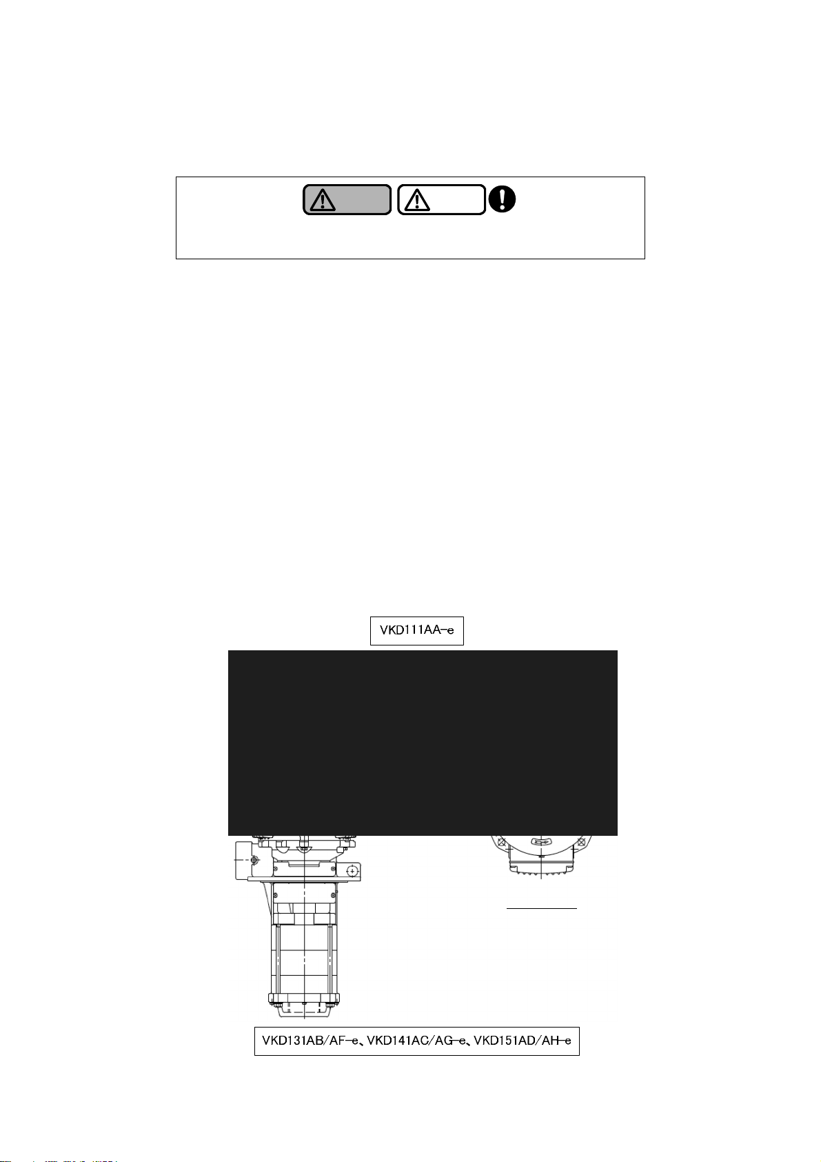
1.3 Location of warning labels and caution labels
The figure below shows the locations of warning labels and caution labels. If these labels become
dirty and hard to read or if they are peeled off, replace them with a new one.
Warning
Caution
Observe all the warnings and cautions affixed to the machine as well as
those described in this instruction manual.
Electric shock
caution label RoHS seal
Pump nameplate Motor nameplate
Pump nameplate
Electric shock
caution label
RoHS seal
Motor nameplate
View from P-P

2-1
2. Configuration and overview of the pump
This chapter describes the standard specifications. For details, refer to the specifications including
the external dimensions drawing and the internal structure drawing.
Also if you purchased a custom-made product with special specifications, refer to the
specifications including the external dimensions drawing and the internal structure drawing,
because the contents may differ partially.
Caution
Do not use this product under any conditions other than those provided in
the specifications. Otherwise, an electric shock, a fire, leaks, or failures
may occur.
2.1 Part names and functions
Motor
Discharge port
Suction port (Strainer)
Air vent
Removes the air in the pump to prevent dry run, if it is
impossible to open the discharge piping to the atmosphere.
Side plate
2.2 Type description
Warning Caution
Be sure to keep the side plates and strainer installed when the
pump is running. Failure to observe this may cause an injury.
Model
Output code
(11:0.75kW, 13:1.5kW, 14:2.2kW, 15:3.0kW)
Series No.
Phase (A: 3-phase)
Number of impellers & leg length
[standard: 260 mm (2.2kW or less), 300 mm
(3.0kW), long: 400 mm]
(A: 1 pc., standard, B: 2 pcs., standard,
C: 3 pcs., standard, D: 4 pcs., standard,
F: 2 pcs., long, G: 3 pcs., long,
H: 4 pcs., long)
Top Runner Energy Efficiency Standards
(IE3-equivalent) motor-equipped pump
VKD 15 1 A D -e
2-2
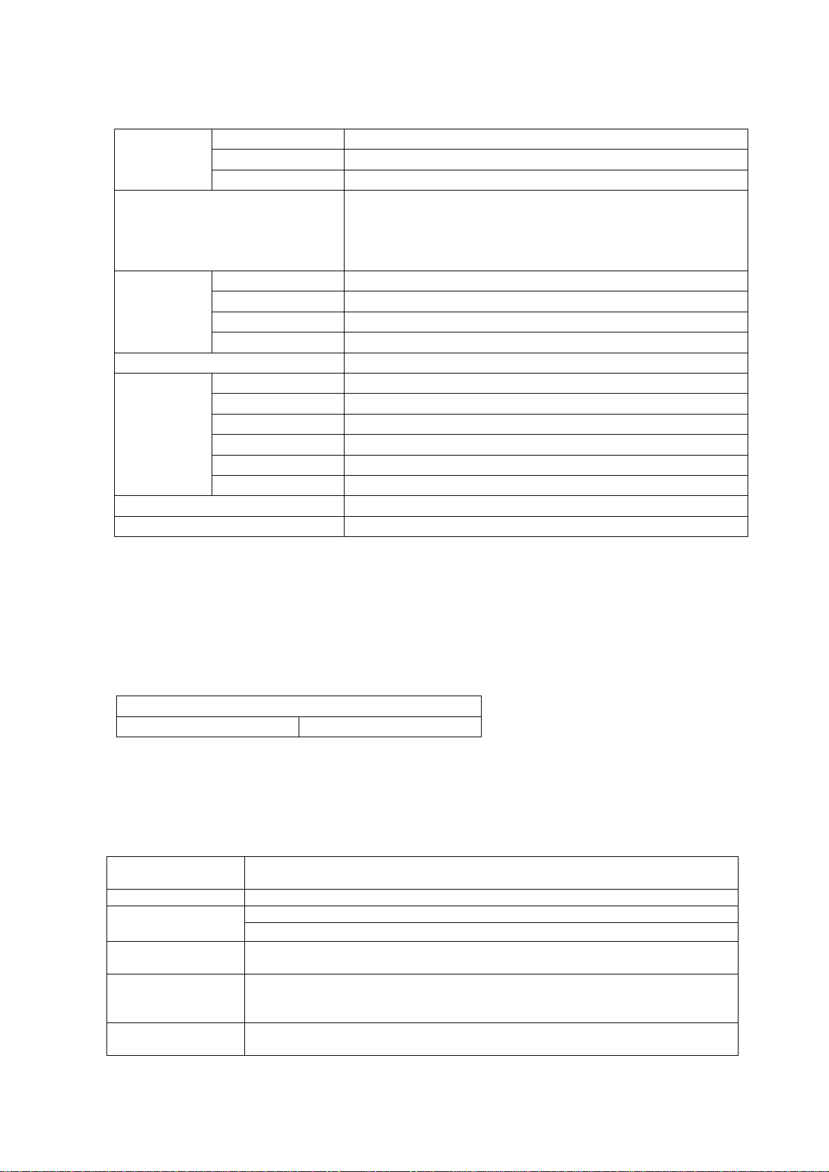
2.3 Standard specifications
Quality Grinding fluid, cutting fluid, etc. after primary treatment Note1
Temperature -20 to 40°C (No freezing is allowed.)
Applicable
liquid Dynamic viscosity See Note2.
Installation location
Indoors, Height above sea level: 1,000 m or less, Ambient
temperature: -20 to 40°C, Humidity: 85% or less (No
condensation is allowed.), Place not exposed to direct sunlight,
Place whose atmosphere contains no corrosive gas, explosive
gas or vapor
Pump leg FC200
Casing FC200
Impeller FC200
Material
Motor spindle S45C
Shaft sealing structure Non-seal (mechanical seal-free) structure
Type Totally-enclosed fan-cooled indoor type
IP protection IP54
Power Note3 3-phase 50/60Hz 200/200-220V
Insulation class Class F
Number of poles 2P
Motor
Standard IEC60034-1
Noise[dB(A)] 77
Coating color Munsell N1
Note1 Notice that the liquid in question cannot be used with water and special liquids such as printing liquids
and acidic liquids. For other special liquids (ceramic etc.), contact Teral Inc.
Note2 When the dynamic viscosity of liquids used becomes higher than that in the table below, the useful life of
the motor may become shorter, leading to a burnout. Be sure to use a liquid with a dynamic viscosity
lower than its lime value in the table below. In addition, the dynamic viscosity of a liquid may drastically
increase with decreasing temperature of the liquid. When using a liquid, confirm the dynamic viscosity of
the liquid when its temperature is lowest.
The characteristics of the pump deteriorate as the dynamic viscosity of liquid used increases.
Applicable limit value of dynamic viscosity [mm2/s]
Operation at 50Hz / 60Hz 75
Note3 Limit the fluctuations of the power voltage within ±10% of the rated voltage, and also limit the fluctuations
of the frequency within -5% to +3% of the rated value. Avoid continuous operation if the voltage is not
within the range of ±5% of the rated value or if the frequency is not within the range of ±2% of the rated
value.
* This product is labeled with a self-declaration CE mark and complies with the Essential Safety
Requirements (ESRs) of the "EU (EC) Directive. The following are the general descriptions.
Manufacturer Teral Inc. 230 Moriwake, Miyuki-cho, Fukuyama-city, Hiroshima 720-0003
Japan
Object product VKD-e model coolant pump
Machinery Directive 2006/42/EC
Standards EN 809/AI:2009、EN ISO 12100:2010、EN 60204-1/A1:2009
Manufacturer
(Japan) Teral Inc., Hiroshima
Administrator
(EU nation)
Shiran Tower 5F Luzna 716/2 160 00 Vokovice, Praha 6
CZECH REPUBLIC
Person in charge: Tomohisa Yamamoto
Place of declaration Hiroshima, Japan
Manager: Taiji Monden
*

2-3
2.4 Nameplate entries
The specifications of the pump are shown on the nameplate. When you receive the pump, check the
nameplate to verify that the product is exactly what you ordered. Be sure to confirm the model,
motor output, frequency and voltage.
If any part of the product should be different from what you ordered, contact the vendor from which
you purchased the product.
Keep the nameplate easy to check without placing an obstacle in front of it or removing it.
Caution
Do not allow the pump to operate with a frequency beyond 60 Hz.
Doing so may overload the motor, causing it to burn out.
2.5 Specification table
• Standard leg Type
Specifications VKD111AA-e VKD131AB-e VKD141AC-e VKD151AD-e
Output (kW) 0.75 1.5 2.2 3.0
Rated voltage (V) 200 200
220 200 200
220 200 200
220 200 200
220
Frequency (Hz) 50 60 50 60 50 60 50 60
5.0 9.1 12.1 16.2
Rated current (A) 4.7 4.9 7.6 7.9 12.0 10.7 14.5 14.6
32.5 45.5 72.0 115
Starting current (A) 34.0 36.0 49.0 50.0 78.0 79.0 120 126
Discharge rate (L/min) 80 to 300 100 to 400 80 to 400 100 to 500 80 to 400 100 to 500 80 to 400 100 to 500
Total head (m) 8 to 4 12 to 4 20 to 7 28 to 7 29 to 9 40 to 9 40 to 14 54 to 14
Applicable limit value of
dynamic viscosity (mm2/s) 75 75 75 75 75 75 75 75
Note 1) The discharge quantity / total head is indicated with the value when tested at a dynamic viscosity of 1 mm2/s(equivalent to normal-temperature
fresh water). Notice that the pump cannot be used with water.
Note 2) The rated current in the above table (current value stated on the pump nameplate) is the recommended preset current value of the protective
device.
• Long leg 4Type
Specifications VKD131AF-e VKD141AG-e VKD151AH-e
Output (kW) 1.5 2.2 3.0
Rated voltage (V) 200 200
220 200 200
220 200 200
220
Frequency (Hz) 50 60 50 60 50 60
9.1 12.1 16.2
Rated current (A) 7.6 7.9 12.0 10.7 14.5 14.6
45.5 72.0 115
Starting current (A) 49.0 50.0 78.0 79.0 120 126
Discharge rate (L/min) 80 to 400 100 to 500 80 to 400 100 to 500 80 to 400 100 to 500
Total head (m) 18 to 4 25 to 2 27 to 7 38 to 7 37 to 11 50 to 8
Applicable limit value of
dynamic viscosity (mm2/s) 75 75 75 75 75 75
Note 1) The discharge quantity / total head is indicated with the value when tested at a dynamic viscosity of 1 mm2/s(equivalent to normal-temperature
fresh water). Notice that the pump cannot be used with water.
Note 2) The rated current in the above table (current value stated on the pump nameplate) is the recommended preset current value of the protective
device.
Symbol Item
1 Type
2 Motor output (kW)
3 Nominal discharge diameter (B)
4 Total head (m)
5 Discharge rate (L/min)
6 Frequency (Hz)
7 Voltage (V)
8 Current (A)
9 Rotating speed (min-1)
10 Max. permissible rotating speed (min-1)
11 Year of manufacture
12 Instruction manual No.
13 Inboard bearing type
14 Outboard bearing type
15 Production No.
Pump nameplate
2-4
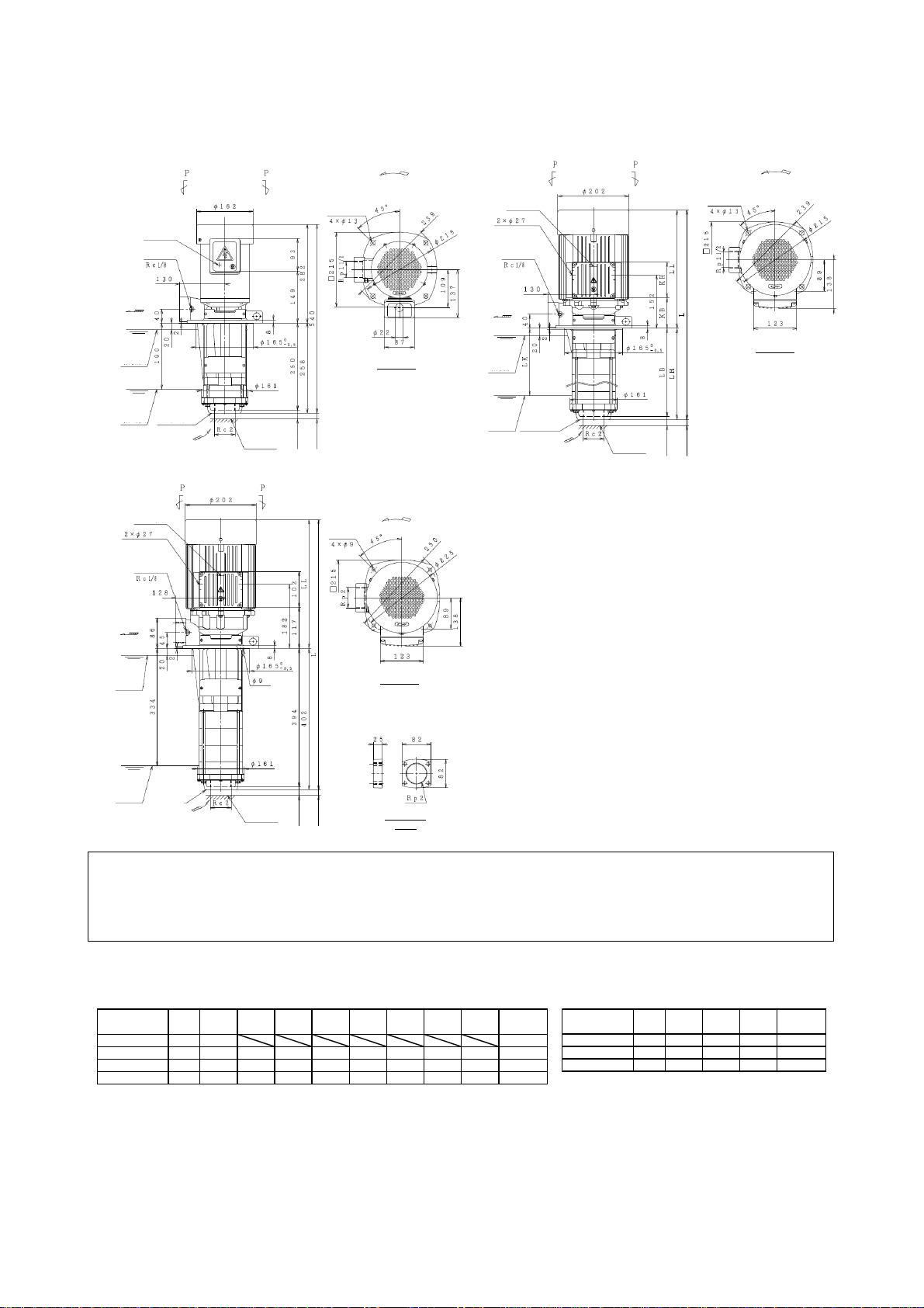
2.6 Dimensional outline drawing and dimensions table
(1) Dimensional outline drawing
Earth
terminal
Air vent
valve
Discharge
port
Rotation direction
Lowest
liquid
level
Highest
liquid
level
Strainer
Size φ5 Bottom of
the tank
Attachment
holes
Suction
port
View from P
17 or
more
25 or
more
Earth
terminal
Air vent
valve
(With caps)
Discharge
port
Lowest
liquid
level
Highest
liquid
level
Strainer
Size φ5
17 or
more
25 or
more
Bottom of
the tank
Rotation direction
Attachment
holes
Earth
terminal
Air vent
valve
(With caps)
Discharge
port
Lowest
liquid
level
Highest
liquid
level
Strainer
Size φ5
17 or
more
25 or
more
Bottom of
the tank
Rotation direction
Attachment
holes
Suction
port
Suction
portCompanion
flange
Fig.1 Fig.2
Fig.3
View from P
View from P
Drain
These figures use a typical model.
Some parts vary in shape depending on the model and specifications. Because some of the specifications
may be changed due to design changes or for other reasons, please request the delivery specification
when implementing your plan.
(2) Dimensions table
・Standard leg Unit:mm ・Long leg Unit:mm
Model Figure 出力
kW KB KH LB LH LK LL L Estimate
d mass Model Figure 出力
kW LL L Estimate
d mass
VKD111AA-e 1 0.75 25 VKD131AF-e 3 1.5 366 768 40
VKD131AB-e 2 1.5 87 102 250 258 190 336 594 35 VKD141AG-e 3 2.2 366 768 42
VKD141AC-e 2 2.2 87 102 250 258 190 336 594 37 VKD151AH-e 3 3.0 394 796 50
VKD151AD-e 2 3.0 87 102 298 306 238 364 670 45
2-5
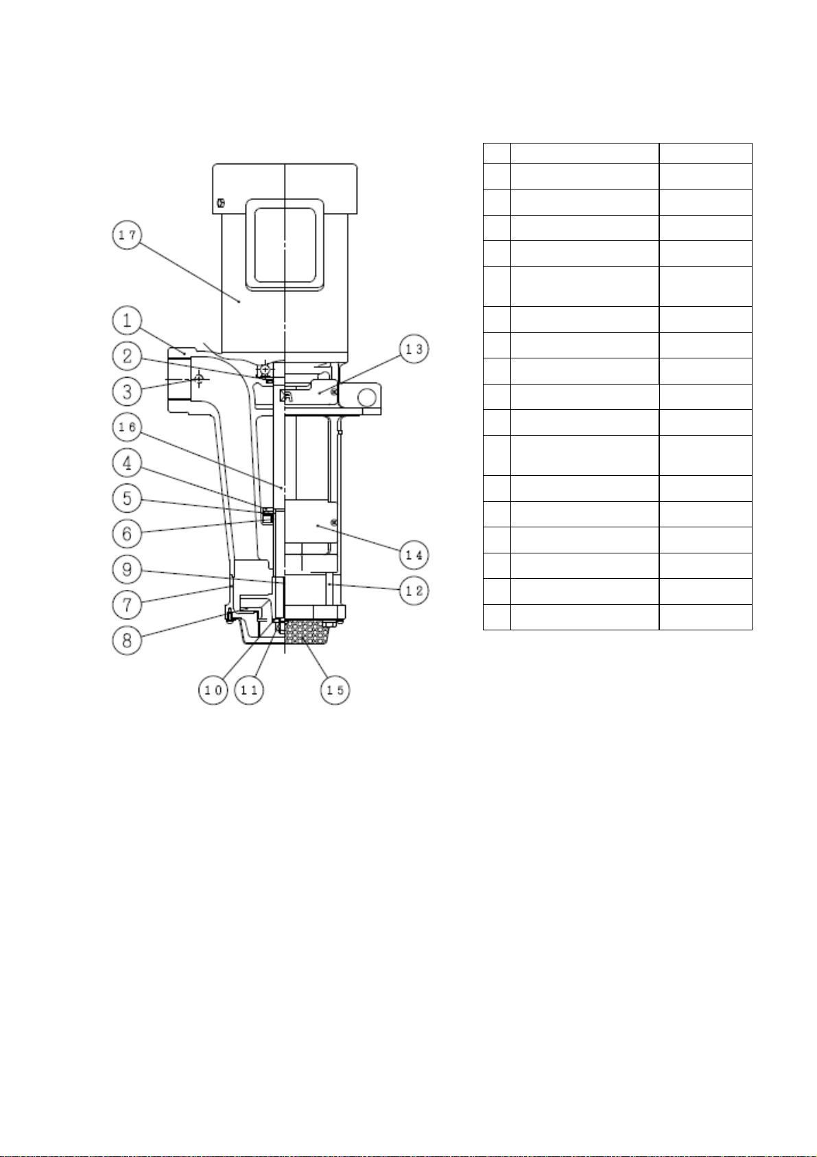
2.7 Internal structural drawing
№Part name Material
1 Pump leg FC200
2 Oil seal NBR
3 Air vent valve SUS
4 Oil deflector SUS304
5Hexagon socket
head screw SCM435
6 O-ring Fluororubber
7 Casing FC200
8 Impeller FC200
9 Key S45C-D
10 Washer SPCC
11 Hexagon nut
(left-hand thread) SS
12 Tight bolt SS
13 Side plate SPCC
14 Side plate SPCC
15 Strainer SPCC
16 Motor shaft S45C-D
17 Motor -
Note) The structure and others are subject
to change without notice.

2-6
№Part name Material №Part name Material
1 Pump leg FC200 10 Key S45C-D
2 Oil seal NBR 11 Washer SPCC
3 Air vent SUS 12 Hexagon nut (left-hand thread) SS
4 Oil deflector SUS304 13 Tight bolt SS
5 Hexagon socket head screw SCM435 14 Side plate SPCC
6 O-ring
Fluororubber 15 Side plate SPCC
7 Casing FC200 16 Strainer SPCC
8 Casing FC200 17 Motor shaft S45C-D
9 Impeller FC200 18 Motor -
Note) The structure and others are subject to change without notice.
3-1
3. Transportation, conveyance, storage and installation
3.1 Precautions for transportation, moving and storing the pump
(1) Do not unpack the container unnecessarily.
If you unpack the container unnecessarily, securely pack again in such a manner that the
product body does not jump out of it and fall down during transportation, conveyance or storage.
(2) When you transport, move, or store the pump, ensure that the pump is located in a
well-ventilated place with minimum exposure to dust and moisture in an environment at an
ambient temperature of -25 to 55 degrees Celsius and humidity of lower than 85%RH. The
packing materials, made mainly of corrugated cardboards, break more easily when they absorb
moisture.
(3) Check the orientation of the container and then place it in the correct orientation (not upside
down).
(4) Do not stack the containers of the product more than the allowable number of units indicated on
the packing material.
The maximum permissible number of stacks for this product is four.
(5) Use extreme care so as not to give an impact or offset load to the pump during conveyance or
transportation. The container may greatly incline depending on its center of gravity.
Warning
Before transporting or moving the product, confirm the weight of each unit
by referring to the catalog, dimensional outline drawing, and other
documents, and then determine the appropriate method.
Caution
When lifting the product by hand, give attention to its center of gravity and
weight. Do not allow any product heavier than 15 kg to be lifted by a single
person. Otherwise, it may put strain on the body, thus leading to an injury.
3.2 Before using the pump
When you receive the pump, check the following points first.
If there are any problems, contact the vendor from which you purchased the product.
Caution
Ensure that the delivered container is placed in the correct orientation (not
upside down) before unpacking. Pay special attention to nails especially
when opening a wooden crate. Otherwise, you may get injured.
(1) Check the nameplate to verify that the delivered product is exactly what you ordered. (Refer to
2.4 "Nameplate entries”, page 2-3).
(2) No part of the product is damaged during transportation.
(3) All fastening parts including bolts and nuts are securely tightened.
(4) All the accessories that you ordered have been delivered.
Warning
Do not hold the strainer on the tip of the pump during handling. Failure to
observe this may cause the strainer to come off, resulting in an injury or
breakage.

3-2
Caution
Do not allow the pump to operate with a frequency beyond 60 Hz.
Doing so may overload the motor, causing it to burn out.
3.3 Precautions for installation
Warning
Before rotating the pump shaft by hand to check it, be sure to turn off the
main power. Sudden operation of the pump may cause an accident.
(1) Install the product in a well-ventilated place with minimum exposure to dust and moisture.
(Refer to 2.3 “Standard specifications”.) In particular, avoid installing the product in a place
where the liquid used is splashed on the motor section.
Warning
Do not install the product in a place exposed to high temperature and
moisture.
Failure to observe this may cause heating, ignition and electric leakage.
(2) Install the product in such a way that the motor can take in air.
(3) Select a flat place for the mounting surface and then install the product so as not to rattle.
(4) Select a place convenient for maintenance and inspection. Ensure maintenance clearances.
(5) The mounting surface should be strong enough to prevent vibration from being amplified when
the pump is running.
(Restrict the total amplitudes in X, Y and Z directions (see the
right figure) to 33μm at 50 Hz and 29μm at 60 Hz during pump
operation.)
(6) It is necessary to make a mounting hole larger than the outside
diameter of the pump section so as to put the pump section into
the tank (oil tank). See the dimensional outline drawing.
(7) Install the product so that the pump shaft becomes vertical.
(8) Use the product with the pump section immersed under the oil
level. The suction port should be at least 17 mm away from the
bottom surface of the tank (oil tank) to prevent the strainer from
getting clogged with cutting powder, dirt, etc. If it is conceivable
that cutting powder, dirt, etc. are deposited on the bottom of the
tank, ensure as large a distance as possible at the design
stage.
Note
The oil level in the tank (oil tank) should always be above the
lowest oil level.
Keep a distance of at least 17 mm from the pump suction plane
to the tank (oil tank).
(9) The product is coated, but if it is overcoated to another color for unavoidable reasons, lightly
roughen the product surface with sand paper and then coat it. The adhesion properties of the
coating film are improved. (Be sure to check that a paint to be used is applicable to
overcoating.)
X: Measurement
direction
Z: Measurement point
X, Y: Measurement
point
Y: Measurement
direction
Z: Measurement
direction
Min. 17 mm
Suction
Bottom of
the tank
Highest
liquid level
Lowest
liquid level
Discharge

3-3
(10) When the liquid leaks from the product, install it in a place where it is not subjected to
secondary damage.
(11) If the system could be exposed to the freezing temperature in winter, be sure to apply
antifreeze measures such as heat insulation and heater installation to the pump, valves, piping,
etc.
(12) Install the pump securely.
Recommended size of pump mounting bolt:
VKD111AA-e, VKD131AB-e, VKD141AC-e, VKD151AD-e: M10
VKD131AF-e, VKD141AG-e, VKD151AH-e: M8
Note
Fasten the pump with bolts securely. Incomplete fixation may cause a
problem such as abnormal vibration.
(13) When lifting the pump, put ropes etc. through its lifting holes and then lift it up.
Do not lift the pump together with the equipment to which it is attached. Failure to observe this
may cause the pump to break and fall down.
(14) Use extreme care so as not to give an impact or offset load to the pump section during pump
lifting or conveyance. The pump may greatly incline depending on its center of gravity.
Warning
Before hoisting the equipment, refer to the catalogue or external
dimensions drawing etc. and ensure that the total weight of the equipment
does not exceed the rated load of the hoisting device.
Warning
Do not use the pump or install any parts with the pump lifted up.
Otherwise, the unit may fall down.
Caution
When lifting up the pump, make sure the center of gravity position.
Otherwise, the unit may overturn or fall, resulting in injury and/or damage.
Caution
When lifting the product by hand, give attention to its center of gravity and
weight. Do not allow any product heavier than 15 kg to be lifted by a single
person. Failure to observe this may put a burden on the body, leading to
an injury.
(15) If the temperature of the liquid used is low, dew condensation may occur in the motor during a
pump stop. Take condensation prevention measures such as installing in a fully dry room or
heating and insulating the motor during a stop.
(16) Carry out refinish painting with a period appropriate to a use environment. Threaded parts,
worked areas, coated parts for rust prevention and other parts may rust may depending on use
environments such as high humidity and dew condensation.
(17) Do not put a cover or a filter over the motor, or it may increase the temperature inside the motor
and lead to breakage, fire, etc. of the product.
3-4
3.4 Precautions for piping work
(1) The pipes should be as short and straight as possible (with minimal joints and valves). Use
pipes whose bore size is equal to or larger than that of the pump. Piping which is thin and has
many bends may decrease the delivery volume.
(2) Be sure to provide pipe supports so as to prevent the weight of the pipes from acting on the
pump body.
Caution
Avoid the weight of the pipes from acting on the pump.
Failure to observe this may cause the pump shaft from coming off center,
resulting in equipment breakage, vibration and noise.
(3) Do not forcibly screw the pipe into the pump. Doing so may break the joint.
(4) Lay the pipes securely in such a way that the pipe connections are kept completely airtight
without leakage. Prevent liquid leakage and air leakage by use of seal tape, liquid packing or
other means. The seal tape should be wound reliably so as not to block up the piping.
(5) Use a tank (oil tank) with as larger a capacity as possible.
* A recommended capacity is at least three times the delivery volume per minute.
Too small a capacity may cause problems such as causing the liquid temperature to rise up,
causing the strainer to get clogged with cutting powder, and causing the delivery volume to
decrease due to the occurrence of air bubbles.
When pouring a liquid used into a tank (oil tank), slowly pour air so as not to trap air in.
(6) Do not allow a large amount of foreign matters such as cutting powder, dirt, or the like in the
pump section. Failure to observe this may clog the pump strainer, break the pump, or promote
the performance degradation. Perform the primary treatment by filtration with a mesh net, chip
conveyor or magnetic separator, before pump startup.
(7) If water hammer may occur, attach a pressure damper (e.g. accumulator).
(8) The companion flange type pump is packaged with a companion flange for the discharge port.
Use if necessary.
(9) If there is an upward curve of the discharge pipe, ensure that air can be vented from the
section.
(10) If you provide an escape pipe on the pump discharge side, provide a sluice valve in the middle
of the escape pipe to adjust the relief volume.
Note
If the amount released from the escape pipe is too much, the temperature
of the liquid in the tank (oil tank) comes to rise easily.
(11) On completion of the piping work, clean the inside of the tank (oil tank) to prevent the suction of
foreign matter.
3.5 Precautions for wiring work
Danger
Use high-quality wiring equipment and devices, and carry out wiring work
safely and securely according to the technical standards for electrical
facilities, as well as the indoor wiring regulations.
Only qualified personnel such as licensed electrical engineers are allowed
to carry out electrical wiring work. Unqualified persons are prohibited by
law to carry out wiring work, and it is very dangerous.

3-5
Danger
Securely connect the terminals of the power cable. Loose terminals may
cause an open phase fault, which causes the motor to burn out.
(1) For the size of the power cable, refer to the following:
Type Minimum size of the cable
(200-volt class)
All types 1.6mm
(2) Be sure to install a ground fault interrupter and an overload protection device on the primary
power side of the pump.
* The starting current of the Top Runner Energy Efficiency Standards (equivalent to IE3)
motor-equipped product tends to become higher than that of the standard efficiency (IE1)
motor-equipped product. Therefore, it is necessary to apply and verify an earth leakage circuit
breaker and overload protection device on the occasion of replacement from the IE1
motor-equipped product. (Refer to the startup current and the rated current in 2.5 “Specification
table” .page 2-3.)
If you have any questions, please contact us.
Note
It is necessary to apply and verify a protective device on the primary side of
the pump on the occasion of replacement from the IE1 motor-equipped
product.
If not applied, the protective device may operate at the time of startup.
(3) When connecting to terminals, securely connect to the power according to the below figure.
(Standard voltage product)
* If there are four or more terminals, follow the connection nameplate in the terminal box.
VKD111AA-e VKD131AB/AF-e、VKD141AC/AG-e、VKD151AD/AH-e
Terminl box layout drawing
Motor
terminal
M4
電源端子
M4
アース端子
M5
電動機端子
M4
電源端子
M4
アース端子
M4
Power
terminal
Earth
terminal
Motor
terminal
Power
terminal
Earth
terminal
(4) Be sure to attach a ground wire to prevent an electric shock.
Connect the ground wire to the ground terminal inside the control panel.
Warning
Connecting a ground wire to gas or water pipes is illegal
and extremely dangerous.
Standard orientation of
terminal box
Discharge
port

3-6
(5) Fasten the power cable to the terminal box with a cable lock so that no tensile load acts on the
motor terminal block.
(6) The position of the terminal box relative to the discharge port can be changed in steps of 90
degrees by rearranging the frame of the motor.
If you rearrange the frame of the motor, ask Teral Inc. about the operating procedures.
Warning
Do not change the orientation of the terminal box.
Failure to observe this may cause the liquid to get into the terminal box,
thus imparting an electric shock.
(7) To prevent the motor from being overloaded and burned out, it is recommended to use a thermal
relay for motor protection.
(8) Carry out adequate dust-proofing and drip-proofing by a connector or gland so that cutting
powder and liquid coolant do not get into the terminal box through the external wiring hole.
(9) Pass the power cable through a metal tube or a metal conduit for shielding, and connect a
ground wire to the outer surface of the tube.
(10)Limit the fluctuations of the power voltage within ±10% of the rated voltage, and also limit the
fluctuations of the frequency within -5% to +3% of the rated value. Although you can run the
pump in these ranges, avoid continuous operation if the voltage is not within the range of ±5% of
the rated value or if the frequency is not within the range of ±2% of the rated value. Failure to
observe this may cause the pump to be overloaded, resulting in motor breakage or a fire.
Even if the power fluctuations fall within the allowable ranges, the pump characteristics, motor
characteristics, and the temperature rise of the motor may differ from those at the rated voltage
and frequency.
(11)Precautions for using the inverter drive
• Ensure that the operation current value does not exceed 90% of the rated value.
• Ensure that the minimum frequency is set to 20 Hz.
(Contact us for operation at 20 Hz or below.)
• Contact to the nearest Teral office when using a 400V class model. Protective measures may be
required against the inverter surge.
• An inverter-driven motor generates a magnetic sound which may sound more annoying than
those generated by the drives using unconverted commercial power.
• Although this magnetic sound does not cause an adverse effect on the quality of the motor,
some inverters allow the user to adjust the tone by changing the carrier frequency. However,
changing the frequency may reduce the allowable output of the inverter. Pay particular attention
when selecting the inverter.
• Do not use in such a rotating speed range that the pump and motor vibrate sympathetically
during normal operation.
Caution
Do not allow the pump to operate with a frequency beyond 60 Hz.
Doing so may overload the motor, causing it to burn out.

4-1
4. Operation
4.1 Check items before test operation
4.1.1 Check items related to the electrical system
(1) Check that the fan is correctly wired.
(2) Check that the terminals are securely connected.
(3) Check that the fan is securely grounded.
(4) Check that the setup value of the overload protection device is consistent with the rated current
value of the motor.
Warning
Do not use the product at any voltage other than the rated voltage.
Otherwise, a fire or an electric shock may occur.
4.1.2 Check items related to the pump
Caution
Do not run the pump with its side plates and strainer removed. Failure to
observe this may cause an injury or breakage.
Caution
Do not allow a large amount of foreign matter in the pump section. Failure
to observe this may cause breakage of the sliding parts (e.g. bearings) in
the pump, leakage or unusual noise.
(1) Ensure that the oil level in the tank (oil tank) is above the "lowest oil
level" position.
Caution
Never run the pump idling (operation with oil level being lower than the
lowest oil level) during test operation.Also do not run the pump dry for
more than 30 sec. Failure to observe this may seize up the sliding parts in
the pump.
(2) Check the rotational direction. Normal rotational direction is
counterclockwise rotation when viewed from the motor side. (See the
right figure.)
(3) Rotate the pump shaft by hand to check smooth rotation. To turn the
pump by hand, remove the side plates and then grasp and turn its shaft.
If the rotation is stiff or not uniform, there may be some rusting or foreign
matter inside the pump. Inspect the pump in such a case.
(4) After the rotation by hand, fit the side plates.
Warning
Before rotating the pump shaft by hand to check it, be sure
to turn off the main power. Sudden operation of the pump
may cause an accident.
Rotation
direction
This manual suits for next models
7
Table of contents
Other Teral Water Pump manuals

Teral
Teral LVS-e Series User manual

Teral
Teral LPWE-GS User manual

Teral
Teral VFZ Series User manual

Teral
Teral ASVM Series User manual

Teral
Teral S User manual

Teral
Teral SJS User manual

Teral
Teral Patron SP-20 User manual

Teral
Teral S User manual

Teral
Teral MSU User manual

Teral
Teral NSVM Series Installation instructions

Teral
Teral LHW-e User manual

Teral
Teral VKN Series User manual

Teral
Teral VKN-e Series User manual

Teral
Teral LS2 User manual

Teral
Teral LPS User manual

Teral
Teral VKA Series User manual

Teral
Teral VKA-e User manual

Teral
Teral Patron SP-40 User manual

Teral
Teral Patron SP-10 User manual

Teral
Teral LPE-e User manual


