TERSO TS087 User manual

1TS087 User Manual
RFID DIRECTIONAL
READ POINT - TS087
USER MANUAL

2TS087 User Manual
THIS PAGE INTENTIONALLY BLANK

3TS087 User Manual
Terso RFID Directional Read Point
Terso Solutions, Inc.
5540 Research Park Drive
Madison, WI 53711
U.S.A.
Terso Solutions GmbH
Schildkrötstr. 15
68199 Mannheim
Germany
US: +1 888.376-0257
EU: +49.621.8501.233

4TS087 User Manual
THIS PAGE INTENTIONALLY BLANK

5TS087 User Manual
Terso RFID Directional Read Point
User Manual

6TS087 User Manual
Manual Revision Record
DATE REVISION DESCRIPTION
04 September 2019 1.00 Initial Release

7TS087 User Manual
TABLE OF CONTENTS
Aboutthismanual...................................................................................................................... 08
Getting Started.......................................................................................................................... 08
Getting Help.............................................................................................................................. 12
Optional Ceiling Tile Mount...................................................................................................... 12
Appendix A: Product Specifications......................................................................................... 13
Appendix B: RFID Tags and Tagging........................................................................................ 13
Appendix C: Mounting Guidelines............................................................................................ 14
8TS087 User Manual
ABOUT THIS MANUAL
The Terso RFID Directional Read Point (TS087) allows you to automatically track RFID-
tagged inventory traveling in and out of a specic area such as an operating room, point of
manufacture, stockroom, etc. This manual provides information on setting up and using the
Terso RFID Directional Read Point and its accessories.
Note: An on-site survey will need to be conducted before any install occurs as special
mounting, congurations, or other hardware may be needed.
Introduction
Notational Conventions
This document uses the following conventions:
• Bullets (•) indicate:
- Action items
- Lists of alternatives
- Lists of required steps that are not necessarily sequential
• Sequential lists (e.g., those that describe step-by-step procedures) appear as
numbered lists
• Note: indicates something of special interest or importance to the reader. Failure to read
the note will not result in physical harm to the reader, equipment, or data.
CAUTION This symbol indicates that if this information is ignored, the possibility of
data or material damage may occur.
1. Terso RFID Directional Read Point (TS087), Jetstream Enabled Directional Portal
2. Power Supply
3. AC Cord
4. Ethernet Cable
5. Security screw and security screw tool (TORX)
6. VESA Mount & Associated Hardware
7. Terso RFID Directional Read Point (TS087) Setup Guide
1. Remove all items from the shipping boxes and place near location to be installed
2. Verify all components are included by referencing the “COMPONENTS” section above
3. If any components are missing, please call Terso’ Product Development Team for
assistance at (608) 298-4100.
1. Placement considerations
a. Where (near door, above door, ceiling height, etc.)
b. Only one path to read the entire scanning area
Locating the Device
Unpacking the Terso RFID Directional Read Point
Components
GETTING STARTED
9TS087 User Manual
c. Path of RFID tagged item through the read point path
d. Installing the read point path into a coered ceiling can reduce tag read
performance. The deeper the read point path is mounted into the coered ceiling,
the more imact there is on tag reads.
2. Install the Device at or below the level of HVAC equipment, pipes, and especially
lighting. Not only will such equipment block the Device beams, but orescent lighting
will also create RF noise interference if in the eld of view. This rule applies only when
the HVAC or lighting is below the Device, in the area where tags are to be read.
For example, if the Device were 10 feet away from the other equipment, this rule would not
apply since the equipment is outside of the read area.
Mounting a read point path under any of the following conditions should be
avoided:
Proximity to uorescent lights: Ideally place the Device greater than a foot away from any
uorescent lighting xture. The reason for this is that the ballasts can oscillate in the data
bands causing RF interference.
A scenario where there is a metal impediment between the tagged item and the Device.
Given that metal blocks the RFID signals, a tagged item’s readability will be greatly reduced if
it is blocked by metal.
Placement directly under or next to a re suppression nozzle (sprinkler): Devices are not
water-resistant.
The recommended mounting for the Terso RFID Directional Read Point (TS087) is
by suspended ceiling mounting. The Device comes complete with a VESA mount for
customizable mounting.
1. Location
a. Ceiling height to be between 8 ft. and 15 ft
b. Ceiling located between 2 ft. and 4 ft. of the door opening
2. Position
a. In / Out Direction must be considered
b. Position as close to the door opening as possible to achieve accurate tag reads
CAUTION Mounting the RFID Directional Read Point (TS087) under any of the
following conditions should be avoided:
i. Proximity to uorescent lights: Ideally place Devices greater than a foot away to
prevent RF interference
ii. A scenario where there is a metal impediment between the tagged item and the
Device. Given that metal blocks the RFID signals, a tagged item’s readability will
be greatly reduced if it is blocked by metal
iii. Placement directly under or next to a re suppression nozzle (sprinkler): these
Devices are not water-resistant
3. Cabling
a. There is a dedicated trough for positioning the cables from the Device to/through
the ceiling mount. Always make sure you route the cables through this path.
4. Physical Mounting
Mounting the Device
10 TS087 User Manual
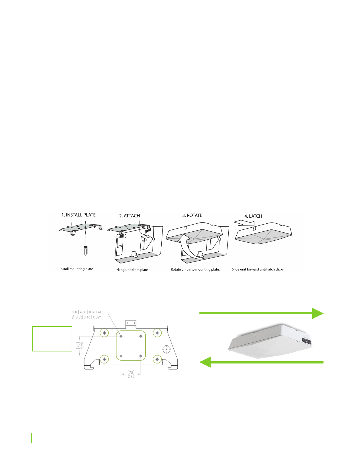
a. Hang the Device from the mounting plate from a securely installed ceiling mount, but
do not latch. See Figure 1.
b. If using the DC Power Supply, Route the power supply cable from the Power Supply
to the recessed space on the back of the Device using the cable slot or the hole in
the mounting plate. Connect the power supply cable to the 24 VDC locking connector
on the Device. See “Connecting the Device” for specic instructions.
c. If using PoE for power, route the Ethernet network cable from a LAN outlet to the
recessed space on the back of the Device using the cable slot or the hole in the
mounting plate. Connect the Ethernet cable to the PoE Ethernet port.
d. Once the power and Ethernet cables are connected, lift the Device against the
mounting plate and securely lock it into position using the latch and security screw.
Once the security screw is installed, the Device cannot be removed from the
mounting plate.
e. Alternate mounting – The Device mounting plate allows the Device to be bolted to any
structure. There are clearance holes in the plate that accommodate an M4 (metric) or
a #8 (SAE) bolt / screw. See Figure 2.
f. Direction: See gure 3 for directional specic mounting.
6. Mounting recommendation
a. The recommended mounting for the Terso RFID Directional Read Point (TS087) is by
suspended ceiling. The Device comes complete with a VESA mount for customizable
mounting of the Device. If you would like information and pricing for the optional 2’ x 2’
Ceiling Tile mounting Device, please contact Terso Customer Service.
VESA Mounting Plate. Green squares on indicate VESA
mounting holes. Circles indicate structure mounting holes.
FIGURE 2
ENTER or aggregate* ADD
EXIT or aggregate REMOVE
FIGURE 3
Default setting. The direction for ADD/REMOVE can
be changed in the Device parameters. Should the
workow dictate a need to change this, please con-
tact Terso Solutions for
instructions.
FIGURE 1
Attaching the RFID Directional Portal to the mounting plate.
LED
Location
11TS087 User Manual
Connecting the Device
1. Power
a. The Terso RFID Directional Read Point (TS087) is designed to be a Power over
Ethernet (PoE) Device. However, should PoE not be available, you may use the
external power supply included in the packaging.
b. There are two methods for powering the Device:
i. IEEE 802.3af (Power over Ethernet) compliant source
ii. Power supply, included, with 24Vdc output, rated minimum 2.1A
c. The Device operates at the Class 3 limit for PoE power (for a standard 100 meter
length cable).
Important: Terso does not reccomend connecting both a PoE and the external power supply to
the Device.
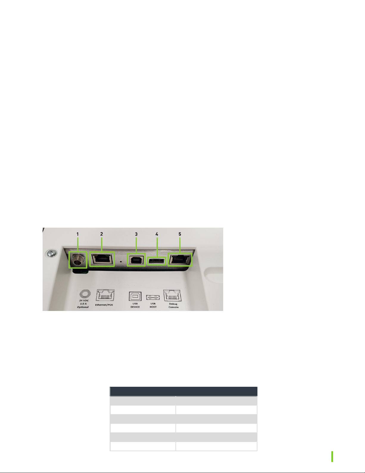
2. Connection (See Figure 4)
a. Before plugging in the Device to the optional DC power supply, plug the Ethernet
cable from the source into the Device. If the LED turns RED, this means PoE is
available and no DC power supply is necessary.
b. If PoE is unavailable, plug the DC power supply into the Portal in the ‘Power’ port.
c. Plug the AC cord into the Power supply
d. Plug the AC cord into a 115V source
e. Verify LED status is in the “Powered’ or RED state when it is rst plugged into an AC
outlet.
f. See the CONNECTIONS section following this step for the physical location and types
of connections available.
FIGURE 4
1. Power (24V, 1A)
2. PoE / Ethernet
3. USB Device (Not Needed)
4. USB Host (Not Needed)
5.Console connection for Terso
Setup and Programming
3. Boot Sequence
a. Boot sequence begins when power is supplied to the Device. This sequence typically
completes within 60 to 120 seconds.
b. After the Device is powered, and connected to a network, verify the exterior LED is
ashing BLUE throughout the connection sequence.
c. Once the Device is connected, the LED will turn a solid BLUE. The Device is now
ready to provide data to Jetstream
4. LED Status Indicator
LED STATE PORTAL STATE
O O (No power supplied)
RED- Solid Powered
YELLOW - Solid Ready
BLUE- Solid Connected
RED- Blinking Fault condition occurred
Blue- Blinking Connecting

12 TS087 User Manual
Support
Terso’s RFID Directional Read Point (TS087) has many RF Performance settings that can
be changed to improve RFID tag reads such as RFID Power, read sensitivity, tag population,
and others. If you are having issues achieving consistent tag reads, please contact
Terso’s Product Management team at (608) 298-4100. You may also contact the Product
Management team if you are experiencing problems with your Device, such as connectivity
issues or power-up issues.
Please make sure you have the Device Digital Serial Number (DSN) ready for reference.
This DSN is on a label on the exterior of the Device near the “Powered by Terso” label.
Sta are available during Terso’s standard business hours: M-F, 8AM-5PM CT. Response
times are typically a few business hours.
GETTING HELP
5. Jetstream Aggregates
a. A Jetstream Aggregate is an event that represents a transaction/change to the
Devices tags.
b. These are events that captures what RFID tags were added and/or removed from
the Device, along with the pass RFID (if applicable) that was provided to access
the Device.
Raw Aggregate example:
{ “PassRd”: “0123456789”,
“Removes”: [
“AD4424044149F1765B0000CF”,
“AD4424044149FB7B5C0000D0”],
“Device”: “MyDeviceName”,
“ReceivedTime”: “2018-05-19T13:23:44Z”,
“Type”: “AggregateEvent”,
“EventId”: “a85745f7-a348-4454-8a97-8eee2aeef853”,
“EventTime”: “2018-05-19T13:23:36Z”,
“Version”:2 }
OPTIONAL CEILING TILE MOUNT
The recommended mounting for the Terso RFID Directional
Read Point (TS087) is by suspended ceiling mounting. The
Device comes complete with a VESA mount for customizable
mounting in a 2 ft x 2 ft suspended ceiling tile system.
Please contact Terso Solutions for information and pricing of
the Ceiling Tile Mount.
13TS087 User Manual
APPENDIX A: PRODUCT SPECIFICATIONS
DESCRIPTION SPECIFICATION
Environment
Power (PoE) IEEE 802.3af power over Ethernet
Power DC 24Vdc output, rated minimum 2.1A
Power Consumption 7 W idle, 13.8 W typical
Operating Temperature -20 to 50 C (-4 to 122 F)
Operating Humidity 5-95% non-condensing
RoHS RoHS 2011/65/ EU compliant
FCC Class B digital Device, pursuant to Part 15 of the FCC rules
Physical
Dimensions (LxWxH) 18.75 in x 8.66 in x 3.45 in
Ceiling Mount (optional) Typical 2ft x 2ft ceiling tile
Weight (Device only) 5.97 pounds, 7.56 pounds with VESA plate
Coverage area 1000ft² per unit with Monza r6 based RFID tags
(rectangular)
RFID
Frequency 902- 928 MHz
Standard
RAIN RFID: EPCglobal
UHF RFID Class 1 Gen2v2
ISO 18000-63
Modes
Read Point
The Device takes an inventory by reading RFID tags within its eld of view (FOV). An
Aggregate Event add is when the RFID tag is read in the read eld of view. An Aggregate
Event Remove is when an RFID tag exits the read eld of view.
Direction The Device detects the direction of a tag as it transitions across the Device’s eld of view
(FOV). One direction of travel will provide an Aggregate Event Remove.
APPENDIX B: RFID TAGS AND TAGGING
RFID Tags & Tagging
RAIN RFID tag choice and tag placement is critical to a successful deployment. Terso will work
closely with all parties to assist in providing the strongest recommendation for a successful
tagging strategy.
Tags vary from application to application. On-metal, read range, tag orientation, and tag chipset
all can have eects on read performance. Terso recommends an RFID tag using the Monza® R6
UHF RFID tag chip or newer.
Please contact Terso for additional guidelines and suggestions on the proper tag(s) to use for
your specic application.
Variables to Consider When Tagging
Product/packaging material
Metals, liquids, foil, active electrical Devices - These materials will aect the tag performance

14 TS087 User Manual
DO DON’T
DO check if the application surface is clean and dry DO NOT ever bend or crease the tag
DO ensure there are no wrinkles in the tag after
application DO NOT place tag directly on a container with liquid
DO try to keep all tags aligned in the same
orientation
DO NOT apply tags to a curved surface with a diameter smaller
than 3”
DO try to keep all tags aligned in the same
orientation
DO NOT place tag on or near any metal surface or any packaging
containing metal unless it is an ‘On-Metal’ tag
DO prevent tags from contacting each other when
stocked 5-95% non-condensing
DO allow for some separation between tag - ideally
> 1” DO NOT remove and reuse a tag once applied
Dimension of items
Tags should be placed on a product that allows the entire tag and adhesive to be adhered to the
product. Do not allow the tag to overhang over an edge.
Available space is available on the product for applying a tag on a at surface
Stocking orientation requirements may be necessary. Consider the direction in which the tag will
be read.
APPENDIX C: MOUNTING GUIDELINES
Mounting and Deployment Success Factors
A successful Device deployment requires users to understand a range of external factors
that can constrain the use case details and success criteria requirements, including but not
limited to: the physical environment, RFID tag constraints, RFID tag read sensitivity, Device
mounting variations, and conguration settings.
Generally, most deployments require some detailed testing of use cases to ensure the
required outcome is possible within the customer’s typical RF environment.
Terso’s preferred mounting location is on a ceiling near the opening of the entrance or exit to
a specic area.
At a minimum, the following should be considered:
• Verify the model is correct model for the geographical region - US, ETSI (Europe), etc.
• Identify the RFID tag type and performance to ensure the item being tagged can be
read by the Device. (i.e. On-metal tag, tag orientation, tag size, tag sensitivity, item
material)
• Tags with Impinj Monza R6 chips using inlays of at least 70mm long is recommended.
The Monza R6 chip has the best and most consistent read ranges
• Consider the likely area coverage for planning where to install your Device for success
• The Device is designed for installation at heights ranging from 8ft to 15ft. However,
lower ceilings may be used. A typical 8 foot ceiling will have a smaller read area and
may require specic positioning based on the location.
• When deciding on the placement the Device, don’t base placement decisions on the
furniture, racks, cabinets, or other large objects below especially if the positions are
subject to change.
• Install the Device at or below the level of HVAC equipment, pipes, and especially
uorescent lighting.

15TS087 User Manual
• Installing the Device into a coered ceiling can reduce RFID tag read performance.
The deeper the Device is mounted into the coered ceiling, the more impact there is
on tag reads.
Hallway & Ceiling Mounting Guidelines

16 TS087 User Manual
Table of contents
Other TERSO RFID System manuals


