User's Guide
SLUU854–February 2012
bq77908AEVM Evaluation Module
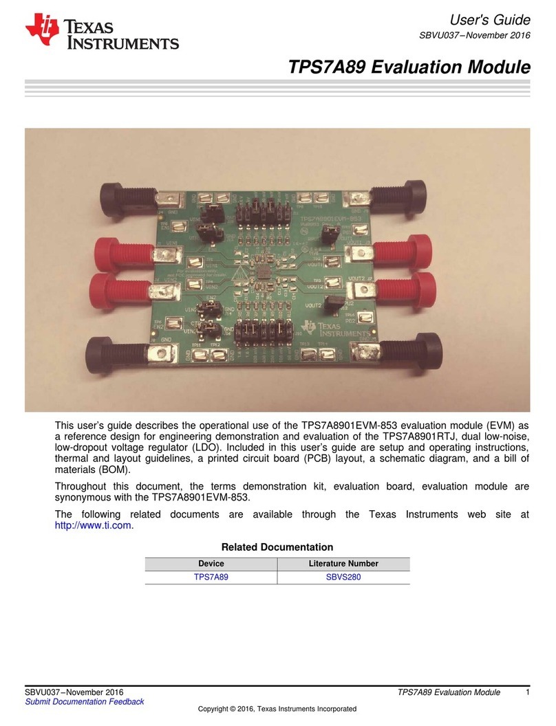
The bq77908AEVM-001 evaluation module (EVM) is a complete evaluation system for the bq77908A, a
4-series to 8-series cell Li-Ion battery protection integrated circuit. The EVM consists of a bq77908A circuit
module and a resistor cell simulator module, which can be used for simple evaluation of the bq77908A
functions. The circuit module includes one bq77908A integrated circuit (IC), sense resistor, power FETs
and all other onboard components necessary to protect the cells from overcharge, overdischarge, short
circuit, and overcurrent discharge in a 8-series cell Li-Ion or Li-Polymer battery pack. The circuit module
connects directly across the cells in a battery. With a compatible interface board and Windows®-based PC
software, the user can view the bq77908A registers and program the IC configuration and protection
limits.
Contents
1 Features ...................................................................................................................... 3
1.1 Kit Contents ......................................................................................................... 3
1.2 Required Equipment ............................................................................................... 3
2 bq77908A Circuit Module and Interfaces ................................................................................ 3
2.1 Circuit Module Connections ...................................................................................... 3
2.2 Signal Descriptions ................................................................................................ 4
3 bq77908AEVM Hardware Connection and Operation ................................................................. 5
3.1 Initial Considerations .............................................................................................. 5
3.2 Connecting the Cell Simulator .................................................................................... 6
3.3 Simulated Battery Connection .................................................................................... 6
3.4 Pack Connections .................................................................................................. 6
3.5 Basic Operation .................................................................................................... 7
3.6 Cell Connections ................................................................................................... 8
4 Software Installation ........................................................................................................ 8
4.1 System Requirements ............................................................................................. 8
4.2 Interface Adapter ................................................................................................... 8
4.3 Installing the bq77908GUI or bq77910GUI Evaluation Software .......................................... 10
5 Software Operation ........................................................................................................ 10
5.1 Menu Commands ................................................................................................. 12
5.2 Working With Register Values .................................................................................. 14
5.3 Status Section ..................................................................................................... 16
5.4 Basic Operation With Software ................................................................................. 17
5.5 Operation With Other Interfaces or Hosts ..................................................................... 17
6 Related Documents From Texas Instruments ......................................................................... 18
7 bq77908AEVM Circuit Description and Configuration ................................................................ 18
7.1 Battery Voltage Clamp ........................................................................................... 18
7.2 Device Power ..................................................................................................... 18
7.3 Cell Monitor Inputs and Configuration ......................................................................... 18
7.4 Ground Connection ............................................................................................... 20
7.5 Current Sense Connections ..................................................................................... 20
7.6 Filter Capacitors .................................................................................................. 20
7.7 FET Circuits ....................................................................................................... 21
7.8 Detection Sensing ................................................................................................ 21
7.9 Output Protection Components ................................................................................. 21
Windows, Microsoft are registered trademarks of Microsoft Corporation.
Aardvark is a trademark of Total Phase, Inc.
1
SLUU854–February 2012 bq77908AEVM Evaluation Module
Submit Documentation Feedback Copyright ©2012, Texas Instruments Incorporated
