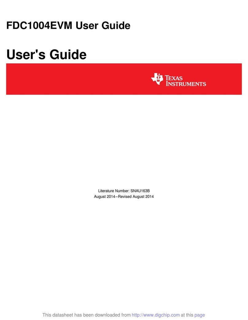
User's Guide
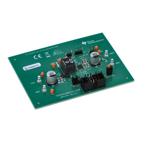
TPS543B22EVM SWIFT Step-Down Converter Evaluation
Module
ABSTRACT
This user’s guide contains information for the TPS543B22 evaluation module (BSR178) and the 20 A
DC/DC converter. Also included are the performance characteristics, schematic, and bill of materials for the
TPS543B22EVM.
Table of Contents
1 Introduction.............................................................................................................................................................................3
1.1 Background........................................................................................................................................................................ 3
1.2 Before You Begin............................................................................................................................................................... 3
1.3 Performance Characteristics Summary............................................................................................................................. 4
2 Configurations and Modifications.........................................................................................................................................5
2.1 Output Voltage................................................................................................................................................................... 5
2.2 Switching Frequency (FSEL Pin)....................................................................................................................................... 6
2.3 Current Limit, Soft-Start Time, and Internal Compensation (MODE Pin)........................................................................... 6
2.4 Adjustable UVLO................................................................................................................................................................6
3 Test Setup and Results.......................................................................................................................................................... 7
3.1 Input/Output Connections.................................................................................................................................................. 7
3.2 Efficiency..........................................................................................................................................................................10
3.3 Output Voltage Regulation................................................................................................................................................11
3.4 Load Transient and Loop Response................................................................................................................................ 12
3.5 Output Voltage Ripple...................................................................................................................................................... 13
3.6 Input Voltage Ripple......................................................................................................................................................... 14
3.7 Synchronizing to a Clock..................................................................................................................................................15
3.8 Start-up and Shutdown with EN....................................................................................................................................... 16
3.9 Start-up and Shutdown with VIN...................................................................................................................................... 17
3.10 Start-up Into Pre-Bias.....................................................................................................................................................18
3.11 Hiccup Current Limit....................................................................................................................................................... 19
3.12 Thermal Performance.................................................................................................................................................... 20
4 Board Layout.........................................................................................................................................................................21
4.1 Layout.............................................................................................................................................................................. 21
5 Schematic and Bill of Materials...........................................................................................................................................25
5.1 Schematic........................................................................................................................................................................ 25
5.2 Bill of Materials.................................................................................................................................................................27
6 Revision History................................................................................................................................................................... 28
List of Figures
Figure 3-1. P1 Efficiency............................................................................................................................................................10
Figure 3-2. P2 Efficiency – Default Configuration......................................................................................................................10
Figure 3-3. U1 Load Regulation ................................................................................................................................................11
Figure 3-4. U1 Line Regulation ................................................................................................................................................. 11
Figure 3-5. U2 Load Regulation ................................................................................................................................................11
Figure 3-6. U2 Line Regulation ................................................................................................................................................. 11
Figure 3-7. U1 Transient Response...........................................................................................................................................12
Figure 3-8. U2 Transient Response...........................................................................................................................................12
Figure 3-9. U1 Bode Plot........................................................................................................................................................... 12
Figure 3-10. U2 Bode Plot......................................................................................................................................................... 12
Figure 3-11. U1 Output Ripple – No Load..................................................................................................................................13
Figure 3-12. U1 Output Ripple – 20 A Load.............................................................................................................................. 13
www.ti.com Table of Contents
SLUUCH6B – SEPTEMBER 2022 – REVISED SEPTEMBER 2023
Submit Document Feedback
TPS543B22EVM SWIFT Step-Down Converter Evaluation Module 1
Copyright © 2023 Texas Instruments Incorporated
