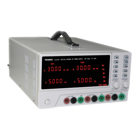
TEXIO PSW Series User manual

B71-0441-11
INSTRUCTION MANUAL
MULTI RANGE DC POWER SUPPLY
PSW SERIES
PSW-360L30
PSW-720L30
PSW-1080L30
PSW-360L80
PSW-720L80
PSW-1080L80
PSW-360M160
PSW-360M250
PSW-360H800
PSW-720M160
PSW-720M250
PSW-720H800
PSW-1080M160
PSW-1080M250
PSW-1080H800

■About Brands and Trademarks
“TEXIO” is the product brand name of our industrial electronic devices.
All company names and product names mentioned in this manual are the
trademark or the registered trademark of each company or group in each
country and region.
■About the Instruction Manual
Permission from the copyright holder is needed to reprint the contents of this
manual, in whole or in part. Be aware that the product specifications and the
contents of this manual are subject to change for the purpose of improvement.
■ About firmware version
This programming manual is required firmware version 2.25 or higher.

CONTENTS
USING THE PRODUCT SAFELY·········································· Ⅰ-Ⅳ
1 GETTING STARTED ............................................................. 1
1-1. PSW Series Overview ............................................................ 1
1-1-1. Series lineup.......................................................................................1
1-1-2. Main Features.....................................................................................2
1-1-3. Accessories........................................................................................2
1-2. Appearance ........................................................................... 4
1-2-1. PSW Front Panel ................................................................................4
1-2-2. Rear Panel...........................................................................................6
1-3. Theory of Operation .............................................................. 9
1-3-1. Operating Area Description...............................................................9
1-3-2. CC and CV Mode ..............................................................................11
1-3-3. Slew Rate..........................................................................................12
1-3-4. Bleeder Control................................................................................13
1-3-5. Internal Resistance ..........................................................................14
1-3-6. Alarms...............................................................................................14
1-3-7. Considerations.................................................................................15
1-3-8. Grounding......................................................................................... 17
2 OPERATION ....................................................................... 18
2-1. Set Up.................................................................................. 18
2-1-1. Line Voltage Connection –Type III Models....................................18
2-1-2. Filter Installation ..............................................................................19
2-1-3. Power Up...........................................................................................19
2-1-4. Wire Gauge Considerations............................................................20
2-1-5. Output Terminals(30V,80V,160V)....................................................20
2-1-6. Using the Output Terminal Cover(30V,80V,160V)..........................22
2-1-7. Output Terminals(250V,800V) .........................................................22
2-1-8. Using the Output Terminal Cover(250V,800V)...............................25
2-1-9. Using the Rack Mount Kit................................................................25
2-1-10. How to Use the Instrument............................................................26
2-1-11. Reset to Factory Default Settings.................................................26
2-1-12. View System Version and Build Date...........................................27
2-2. Basic Operation................................................................... 29
2-2-1. Setting OVP/OCP Levels..................................................................29
2-2-2. Set to C.V. Mode...............................................................................30
2-2-3. Set to C.C. Mode...............................................................................33
2-2-4. Display Modes..................................................................................35
2-2-5. Panel Lock........................................................................................35
2-2-6. Remote Sense ..................................................................................36
2-3. Parallel / Series Operation................................................... 38
2-3-1. Master-Slave Parallel Overview ......................................................39
2-3-2. Master-Slave Parallel Connection................................................... 40
2-3-3. Master-Slave Parallel Operation .....................................................42
2-3-4. Master-Slave Series Overview ........................................................43
2-3-5. Master-Slave Series Connection.....................................................45
2-3-6. Master-Slave Series Operation .......................................................46

2-4. Test Script ........................................................................... 47
2-4-1. Filename of TestScript.....................................................................47
2-4-2. Test Script Settings .........................................................................47
2-4-3. Setting the Test Script.....................................................................48
2-4-4. Load Test Script from USB drive....................................................49
2-4-5. Run Test Script.................................................................................49
2-4-6. Run Test Script (At Startup)............................................................50
2-4-7. Export Test Script to USB ...............................................................50
2-4-8. Remove Test Script..........................................................................51
2-4-9. Test Memory.....................................................................................51
2-4-10. Data structure of the test Script....................................................52
2-4-11. Setting values of the test Script....................................................53
3 CONFIGURATION............................................................... 54
3-1. Configuration Table ............................................................. 54
3-2. Normal Function Settings.................................................... 57
3-3. USB/GP-IB/RS-232C Settings............................................... 60
3-4. LAN Settings ....................................................................... 60
3-5. System Settings .................................................................. 61
3-6. Power On Configuration Settings ........................................ 62
3-7. Calibration........................................................................... 63
3-8. Setting Normal Function Settings ....................................... 63
3-9. Setting Power On Configuration Settings............................ 64
4 ANALOG CONTROL ........................................................... 65
4-1. Analog Remote Control Overview........................................ 65
4-1-1. Analog Control Connector Overview .............................................65
4-1-2. External Voltage Control of Voltage Output ..................................67
4-1-3. External Voltage Control of Current Output ..................................68
4-1-4. External Resistance Control of Voltage Output ............................70
4-1-5. External Resistance Control of Current Output ............................71
4-1-6. External Control of Output.............................................................. 73
4-1-7. External control of Shutdown .........................................................74
4-2. Remote Monitoring .............................................................. 76
4-2-1. External Voltage and Current Monitoring ......................................76
4-2-2. External Operation and Status Monitoring ....................................77
5 Digital Control ................................................................... 79
5-1. Interface Configuration ....................................................... 79
5-1-1. USB Remote Interface .....................................................................79
5-1-2. Configure GP-IB Interface ...............................................................79
5-1-3. Configure RS-232C Interface...........................................................80
5-1-4. Configure Ethernet Connection......................................................80
5-1-5. Web Server Configuration...............................................................81
5-1-6. Sockets Server Configuration.........................................................81
5-1-7. USB Remote Control Function Check............................................82
5-1-8. Web Server Remote Control Function Check................................82
5-1-9. Socket Server Function Check .......................................................83
6 MAINTENANCE .................................................................. 87
6-1. Replacing the Dust Filter..................................................... 87
7 FAQ.................................................................................... 88

8 APPENDIX.......................................................................... 89
8-1. PSW Default Settings .......................................................... 89
8-2. Error Messages & Messages ............................................... 91
8-3. LCD Display Format............................................................. 91
9 Specifications.................................................................... 92
9-1. PSW 360W Type I ................................................................. 92
9-2. PSW 720W Type II ................................................................ 95
9-3. PSW 1080W Type III ............................................................. 98
9-4. Common ............................................................................ 101
9-5. PSW Dimensions ............................................................... 102

I
USING THE PRODUCT SAFELY
■Preface
To use the product safely, read instruction manual to the end. Before using
this product, understand how to correctly use it. If you read the manuals but
you do not understand how to use it, ask us or your local dealer. After you
read the manuals, save it so that you can read it anytime as required.
■Pictorial indication
The manuals and product show the warning and caution items required to
safely use the product. The following pictorial indication is provided.
Pictorial
indication
Some part of this product or the manuals may show this
pictorial indication. In this case, if the product is
incorrectly used in that part, a serious danger may be
brought about on the user's body or the product. To use
the part with this pictorial indication, be sure to refer to the
manuals.
WARNING
!
If you use the product, ignoring this indication, you may get
killed or seriously injured. This indication shows that the
warning item to avoid the danger is provided.
CAUTION
!
If you incorrectly use the product, ignoring this indication,
you may get slightly injured or the product may be
damaged. This indication shows that the caution item to
avoid the danger is provided.
Please be informed that we are not responsible for any damages to the user or
to the third person, arising from malfunctions or other failures due to wrong use
of the product or incorrect operation, except such responsibility for damages as
required by law.

II
USING THE PRODUCT SAFELY
WARNING
!
CAUTION
!
■Do not remove the product's covers and panels
Never remove the product's covers and panels for any purpose.
Otherwise, the user's electric shock or fire may be incurred.
■Warning on using the product
Warning items given below are to avoid danger to user's body and life and
avoid the damage or deterioration of the product. Use the product, observing
the following warning and caution items.
■Warning items on power supply
●Power supply voltage
The rated power supply voltages of the product are 100VAC. The rated power
supply voltage for each product should be confirmed by reading the label
attached on the back of the product or by the “rated” column shown in the
instruction manual. The specification of power cord attached to the products
is rated to 125VAC for all products which are designed to be used in the
areas where commercial power supply voltage is not higher than 125VAC.
Accordingly, you must change the power cord if you want to use the product
at the power supply voltage higher than 125VAC. If you use the product
without changing power cord to 250VAC rated one, electric shock or fire may
be caused. When you used the product equipped with power supply voltage
switching system, please refer to the corresponding chapter in the instruction
manuals of each product.
●Power cord
(IMPORTANT) The attached power cord set can be used for
this device only.
If the attached power cord is damaged, stop using the product and call us or
your local dealer. If the power cord is used without the damage being
removed, an electric shock or fire may be caused.
●Protective fuse
If an input protective fuse is blown, the product does not operate. For a
product with external fuse holder, the fuse may be replaced. As for how to
replace the fuse, refer to the corresponding chapter in the instruction
manual. If no fuse replacement procedures are indicated, the user is not
permitted to replace it. In such case, keep the case closed and consult us
or your local dealer. If the fuse is incorrectly replaced, a fire may occur.

III
USING THE PRODUCT SAFELY
■Warning item on Grounding
If the product has the GND terminal on the front or rear panel surface, be sure
to ground the product to safely use it.
■Warnings on Installation environment
●Operating temperature and humidity
Use the product within the operating temperature indicated in the “rating”
temperature column. If the product is used with the vents of the product
blocked or in high ambient temperatures, a fire may occur. Use the product
within the operating humidity indicated in the “rating” humidity column.
Watch out for condensation by a sharp humidity change such as transfer to a
room with a different humidity. Also, do not operate the product with wet
hands. Otherwise, an electric shock or fire may occur.
●Use in gas
Use in and around a place where an inflammable or explosive gas or steam is
generated or stored may result in an explosion and fire. Do not operate the
product in such an environment. Also, use in and around a place where a
corrosive gas is generated or spreading causes a serious damage to the
product. Do not operate the product in such an environment.
●Installation place
Do not insert metal and inflammable materials into the product from its vent
and spill water on it. Otherwise, electric shock or fire may occur.
■Do not let foreign matter in
Do not insert metal and inflammable materials into the product from its vent
and spill water on it. Otherwise, electric shock or fire may occur.
■Warning item on abnormality while in use
If smoke or fire is generated from the product while in use, stop using the
product, turn off the switch, and remove the power cord plug from the outlet.
After confirming that no other devices catch fire, ask us or your local dealer.

IV
USING THE PRODUCT SAFELY
■Input / Output terminals
Maximum input to terminal is specified to prevent the product from being
damaged. Do not supply input, exceeding the specifications that are indicated
in the "Rating" column in the instruction manual of the product. Also, do not
supply power to the output terminals from the outside. Otherwise, a product
failure is caused.
■Calibration
Although the performance and specifications of the product are checked under
strict quality control during shipment from the factory, they may be deviated
more or less by deterioration of parts due to their aging or others.
It is recommended to periodically calibrate the product so that it is used with its
performance and specifications stable. For consultation about the product
calibration, ask us or your local dealer.
■Daily Maintenance
When you clean off the dirt of the product covers, panels, and knobs, avoid
solvents such as thinner and benzene. Otherwise, the paint may peel off or
resin surface may be affected. To wipe off the covers, panels, and knobs, use
a soft cloth with neutral detergent in it.
During cleaning, be careful that water, detergents, or other foreign matters do
not get into the product.
If a liquid or metal gets into the product, an electric shock and fire are caused.
During cleaning, remove the power cord plug from the outlet.
Use the product correctly and safely, observing the above warning and caution
items. Because the instruction manual indicates caution items even in individual
items, observe those caution items to correctly use the product.
If you have questions or comments about the manuals, ask us or E-Mail us.

1
1 GETTING STARTED
This chapter describes the power supply in a nutshell, including its main
features and front / rear panel introduction. After going through the
overview, please read the theory of operation to become familiar with the
operating modes, protection modes and other safety considerations.
1-1. PSW Series Overview
1-1-1. Series lineup
The PSW series consists of 9 models, divided into 3 different model
types covering 3 power capacities: Type I(360W), Type II(720W) and Type
III(1080 W).
Model name
Type
Voltage Rating
Current Rating
Power
PSW-360L30
Type I
0~30V
0~36A
360W
PSW-360L80
Type I
0~80V
0~13.5A
360W
PSW-360M160
Type I
0~160V
0~7.2A
360W
PSW-360M250
Type I
0~250V
0~4.5A
360W
PSW-360H800
Type I
0~800V
0~1.44A
360W
PSW-720L30
Type II
0~30V
0~72A
720W
PSW-720L80
Type II
0~80V
0~27A
720W
PSW-720M160
Type II
0~160V
0~14.4A
720W
PSW-720M250
Type II
0~250V
0~9.0A
720W
PSW-720H800
Type II
0~800V
0~2.88A
720W
PSW-1080L30
Type III
0~30V
0~108A
1080W
PSW-1080L80
Type III
0~80V
0~40.5A
1080W
PSW-1080M160
Type III
0~160V
0~21.6A
1080W
PSW-1080M250
Type III
0~250V
0~13.5A
1080W
PSW-1080H800
Type III
0~800V
0~4.32A
1080W
Apart from the differences in output, each unit differs in size.
The 720 and 1080 watt models are larger than the 360 watt
models to accommodate the increase in power.
360 W model
Type I
720 W model
Type II
1080 W model
Type III
A
W
V
W
%W10080604020
ISR
C C
DLY
ALM
RMT
C V
VSR
Function OVP/OCP Set Output
PWR DSPLLock/LocalTest
PSW 3 0-3 6 360W
Multi-Range DC Power Supply Voltage
Current
A
W
V
W
%W10080604020
ISR
C C
DLY
ALM
RMT
C V
VSR
Function OVP/OCP Set Output
PWR DSPLLock/LocalTest
PSW 3 0-7 2 720W
Voltage
Current
Multi-Range DC Power Supply
A
W
V
W
%W10080604020
ISR
C C
DLY
ALM
RMT
C V
VSR
Function OVP/OCP Set Output
PWR DSPLLock/LocalTest
PSW 3 0-1 08 1080W
Voltage
Current
Multi-Range DC Power Supply

2
1-1-2. Main Features
Performance
・High performance/power.
・Power efficient switching type power supply.
・Low impact on load devices.
・Fast transient recovery time of 1ms.
・Fast output response time.
Features
・OVP, OCP and OTP/OHP protection.
・Adjustable voltage and current slew rates.
・User adjustable bleeder control to quickly dissipate the
power after shutdown to safe levels.
・Extensive remote monitoring and control options.
・Support for serial*and parallel connections.
*(30, 80, 160 volt models only)
・Power on configuration settings.
・Supports test scripts.
・Web server monitoring and control.
Interface
・Ethernet port (Socket/Web)
・Analog connector for analog voltage and current
monitoring
・USB host port and device port
・Option:GP-IB,RS-232C
1-1-3. Accessories
Standard
Accessories
Part number
Description
CD ROM
User manual, Programming manual,
USB Driver, Test Script Data
Power cord
Depends on Regional and Type.
PSW-009
Output terminal cover(30,80,160 volt models)
PSW-011
Output terminal cover(250,800 volt models)
PSW-012
High voltage output terminal
(250,800 volt models)
GTL-123
Test leads:1x red,1x black
(30,80,160 volt models)
GTL-240
USB Cable
PSW-004
Basic Accessory Kit(30,80,160 volt models)
M4 terminal screw and washers x2
M8 terminal bolts,nuts and washers x 2
Air filter x 1
Analog control protection dummy x 1
Analogcontrol lock level x 1

3
PSW-008
Basic Accessory Kit: (250,800 volt models)
Air filter x1
Analog control protection dummy x1
Analog control lock level x1
Option
Part number
Description
GET-001
Extended terminal(30,80,160 volt models)
GET-002
Extended terminal(250,800 volt models)
PSW-001
Accessory Kit:
Pin contact x 10、Socket x 1
Protection cover x 1
(Compatible with OMRON XG5M-2635-N)
PSW-005
Series operation cable for 2 units
(30,80,160 volt models)
PSW-006
Parallel operation cable for 2 units
PSW-007
Parallel operation cable for 3 units
GRA-410-J
Rack mount adapter (JIS)
GRA-410-E
Rack mount adapter (EIA)
GUG-001
GUR-001
GUR-001A
GP-IB to USB adapter
RS-232C to USB adapter
RS-232C to USB adapter
GTL-240
USB cable
GTL-130
Test leads: 1x red, 1x black
(250,800 volt models)
PSW-010
Air filter (Type II/III)
Driver
Name
Description
texio_cdc*.inf
USB driver

4
1-2. Appearance
1-2-1. PSW Front Panel
PSW-720**** (720W:TypeII)
A
W
V
W
%W10080604020
ISR
C C
DLY
ALM
RMT
C V
VSR
Function OVP/ OCP Set Output
PWR DSPLLock/ LocalTest
720W
Voltage
Current
Multi- Range DC Power Supply
Current
knob
Output
key
Power
switch
USB A
port
Display
Cover
panel
Function
keys
Voltage
knob
PSW-1080**** (1080W:TypeIII)
PSW-360****(360W:TypeI)
A
W
V
W
%W10080604020
ISR
C C
DLY
ALM
RMT
C V
VSR
Function OVP/OCP Set Output
PWR DSPLLock/LocalTest
1080W
Voltage
Current
Multi-Range DC Power Supply
A
W
V
W
%W10080604020
ISR
C C
DLY
ALM
RMT
C V
VSR
Function OVP/OCP Set Output
PWR DSPLLock/LocalTest
360W
Multi-Range DC Power Supply Voltage
Current
Function keys
The Function keys along with the Output key will light up when a
key is active.
Function
Function
The Function key is used to configure the
power supply.
OVP/OCP
OVP/OCP
Set the over current or over voltage
protection levels.
(Long push)Used to release protection
functions that have been activated.

5
Set
Set
Sets the current and voltage limits.
Test
Test
Used to run customized scripts for testing.
Lock/Local
Lock/Local
Locks or unlocks the panel keys to prevent
accidentally changing panel settings.
PWR DSPL
PWR DSPL
Toggles the display from viewing
V/A →V/W→V/A
Press the Current knob to switch the
display from V/W to W/A.
Display indicators
VSR
Voltage Slew Rate
C V
Constant Voltage Mode
RMT
Remote Control Mode
ALM
Alarm on
DLY
Delay Output
C C
Constant Current Mode
ISR
Current Slew Rate
20
40
60
80
100
% W
Power bar
Indicates the current power output as a
percentage.
Voltage knob
Voltage
Sets the voltage.
Setting can be settled when push the knob.
Current knob
Current
Sets the current.
Setting can be settled when push the knob.
Output
Output
Press to turn on the output. The Output key
will light up when the output is active.
USB
USB A port for data transfer, loading test
scripts etc.
Power Switch
Used to turn the power on/off.

6
1-2-2. Rear Panel
PSW-720M160, PSW-720L80, PSW-720L30 (720W)
Output
terminal(+)
Fan
Output
terminal(-)
LAN AC Input
Sense-
terminal
LAN 100 240V
1000VA MAX.
AC
47 63Hz
SER.NO. LABEL
Analog control
connector
Sense+
terminal
USB B
Port
PSW-1080M160, PSW-1080L80, PSW-1080L30
(1080W)
PSW-360M160,
PSW-360L80,
PSW-360L30 (360W)
100 240VAC 1500VA MAX.
47 63Hz
LAN LN
SER.NO. LABEL
AC Input
LAN
100 240V
47 63Hz 500VA MAX.
AC

7
PSW-720H800, PSW-720M250 (720W)
LAN 100 240V
1000VA MAX.
AC
47 63Hz
SER.NO. LABEL
V SN.C. S V
Output
terminals +V
Fan
Chassis
ground
USB B
port
LAN
AC Input
Sense-
terminal
Analog control
connector
Sense+
terminal
Output
terminals -V
PSW-1080H800, PSW-1080H250,(1080W)
PSW-360H800
PSW-360M250
(360W)
LAN LN
SER.NO. LABEL
47 63Hz 1500VA MAX.
AC 100 240V
V VSN.C. S
AC Input
LAN
100 240V
47 63Hz 500VA MAX.
AC
V S N.C. S V

8
Analog Control
Connector
Standard 26 pin MIL connector
(OMRON XG4C Plug).
The analog control connector is used to
monitor current and voltage output,
machine status (OVP, OCP, OTP/OHP
etc.), and for analog control of the current
and voltage output.
Use an OMRON XG5M socket as the
mating socket.
Output Terminals
(30V,80V,160V)
Positive (+) and negative (-) output terminals.
Chassis ground
Sense (-) and Sense (+) terminals.
Output
Terminals
(250V, 800V)
The 250 and 800 volt models use a 9 pin connector and
a plug for the output and sense terminal connections.
The plug is a MC420-38109Z plug by DECA SwitchLab
Inc. This plug is also available separately
V SN.C. S V
Positive (V+) and negative (V-)
output terminals (3 of each).
V SN.C. S V
Chassis ground
V SN.C. S V
Sense (-S) and Sense (+S)
terminals.
USB B port
The USB B port is used for remote control.
Fans
Temperature controlled fans
Ethernet port
LAN
The ethernet port is used for remote control
and digital monitoring from a PC.
Line Voltage Input
(Type I/TypeII)
Type I: PSW-360L30/L80/M160/M250/H800
Type II: PSW-720L30/L80/M160/M250/H800
・Voltage Input: 100~240 VAC
・Line frequency: 50Hz/60Hz
(automatically switchable)

9
Line Voltage
Input
(Type III)
LN
Type III:PSW-1080L30/L80/M160/M250/H800
・Voltage Input: 100~240 VAC
・Line frequency: 50Hz/60Hz
(automatically switchable)
1-3. Theory of Operation
The theory of operation chapter describes the basic principles of operation,
protection modes and important considerations that must be taken into account
before use.
1-3-1. Operating Area Description
Background
The PSW power supplies are regulated DC power supplies
with a high voltage and current output. These operate in CC or
CV mode within a wide operating range limited only by the
output power.
The operating area of each power supply is determined by the
rated output power as well as the voltage and current rating.
For example the operating area and rated power output for the
PSW-360L30 is shown below.
Voltage
Current
30
360W Rated power
10
12 36
PSW-360L30 Operationg Area
When the power supply is configured so that the total output
(current x voltage output) is less than the rated power output,
the power supply functions as a typical constant current,
constant voltage power supply. If however, the power
supply is configured such that the total output (current x
voltage output) exceeds the rated power output, the effective
output is actually limited to the power limit of the unit. In this
case the output current and voltage then depend purely on the
load value.

10
PSW 30V Series Operating Area
0
5
10
15
20
25
30
020406080100
Volt…
Cur…
Po…
0
5
30
Current(A)
Voltage(V)
10
15
20
25
0 20 40 60 80 100
10
12 24 36
30
35
120
Type III
Type II
Type I
72 108
PSW 80V Series Operating Area
0
5
10
15
20
25
30
020406080100
Volt…
Cur…
Po…
Current(A)
Voltage(V)
26.6
4.5 9.0 13.5
80
Type III
Type II
Type I
30 45
40205 10 15 25
035
0
20
40
60
80
90 27 40.5
PSW 160V Series Operating Area
0
5
10
15
20
25
30
020406080100
Volt…
Cur…
Po…
0
20
160
Current(A)
Voltage(V)
40
60
80
140
0510 15 20
180
25
Type III
Type II
Type I
100
120
2.25 4.5 6.75
160
50
14.4 21.67.2

11
PSW 250V Series Operating Area
0
5
10
15
20
25
30
020406080100
Volt…
Cur…
Po…
Current (A)
Voltage (V)
036912 15
Type III
Type II
Type I
1.44 2.88 4.32
250
80
9 13.54.5
250
200
150
100
50
0
PSW 800V Series Operating Area
0
5
10
15
20
25
30
020406080100
Volt…
Cur…
Po…
0
100
800
Current (A)
Voltage (V)
200
300
400
700
01234
900
5
Type III
Type II
Type I
500
600
0.45 0.9 1.35
800
250
2.88 4.321.44
1-3-2. CC and CV Mode
CC and CV mode
Description
When the power supply is operating in constant current
mode (CC) a constant current will be supplied to the load.
When in constant current mode the voltage output can
vary, whilst the current remains constant. When the load
resistance increases to the point where the current limit
(ISET) can no longer be sustained the power supply
switches to CV mode. The point where the power supply
switches modes is the crossover point.
When the power supply is operating in CV mode, a
constant voltage will be supplied to the load, whilst the
current will vary as the load varies. At the point that the
load resistance is too low to maintain a constant voltage,
the power supply will switch to CC mode and maintain the
set current limit.
The conditions that determine whether the power supply
operates in CC or CV mode depends on the set current
(ISET), the set voltage(VSET), the load resistance (RL) and
Other manuals for PSW Series
1
This manual suits for next models
15
Table of contents
Other TEXIO Power Supply manuals
TEXIO
TEXIO PU6-200 User manual
TEXIO
TEXIO PR-A Series User manual

TEXIO
TEXIO PFR-100 SERIES Owner's manual
TEXIO
TEXIO PA10-5B User manual
TEXIO
TEXIO PFR-100M250 Manual
TEXIO
TEXIO PBW Series User manual
TEXIO
TEXIO PW8-3AQP User manual
TEXIO
TEXIO PSF-1200L User manual
TEXIO
TEXIO PDS20-10A User manual
TEXIO
TEXIO PPX Series Owner's manual
