TEXIO PSF-1200L User manual

B71-0060-11
INSTRUCTION MANUAL
REGULATED DC POWER SUPPLY
PSF SERIES
PSF-400L
PSF-800L
PSF-1200L
PSF-400L2
PSF-800LS
PSF-1600L

CONTENTS
USING THE PRODUCT SAFELY·····························································Ⅰ-Ⅳ
1. GENERAL ..........................................................................................................1
1-1. General .......................................................................................................1
1-2. Applicable Products.....................................................................................1
1-3. Features......................................................................................................3
1-4. Accessories.................................................................................................4
2. SPECIFICATIONS..............................................................................................5
3.PRELIMINARY INSTRUCTIONS.....................................................................13
4. DEVICES ON PANELS ....................................................................................15
4-1. Front Panel................................................................................................15
4-2. Rear Panel ................................................................................................19
5. OPERATION PROCEDURES ..........................................................................23
5-1. Connecting AC Power Cable.....................................................................23
5-2. Connecting Load with Output Terminals ...................................................23
5-2-1. Connection with the rear output terminals..........................................23
5-2-2. Connection with the front output terminals.........................................26
5-3. Operation Ranges.....................................................................................27
5-4. Various Setting..........................................................................................27
5-4-1. How to set voltage .............................................................................28
5-4-2. How to set current..............................................................................28
5-4-3. How to set power ...............................................................................28
5-4-4. How to change into power display .....................................................29
5-4-5. How to output.....................................................................................29
5-4-6. How to display the set value in outputting condition...........................30
5-4-7. Howtorotatedisplaypanelby90degrees(forverticalinstallation).............31
5-4-8. How to invalidate on-panel operations (Key lock function).................31
5-5. Various Functions Available on Menus .....................................................32
5-5-1. Preset function (01)............................................................................33
5-5-2. OVP/OCP function (02)......................................................................34
5-5-3. Hi-Ωfunction (03)................................................................................35
5-5-4. OFF timer function (04)......................................................................36
5-5-5. Sequence function (05)......................................................................38
5-5-6. External control (external voltage, external resistance) (06) ..............41
5-5-7. External control (On/Off) (07).............................................................43
5-5-8. Delay function (08).............................................................................44
5-5-9. Tracking function (09) ........................................................................46
5-5-10. Master-slave function (10)................................................................47
5-6. Output Voltage Remote Sensing...............................................................49
5-7. External Control Functions........................................................................50
5-7-1.To assembletheconnector XG5M-2635-N............................................50
5-7-2 Output voltage monitorand outputcurrentmonitor ...................................51
5-7-3. Constant-voltage (CV) control with external voltage or resistance.............52
5-7-4. Constant-current (CC) control with external voltage or resistance.............53
5-7-5. Output ON/OFF with external contacts ..............................................54
5-7-6. Alarm function using external contacts...............................................55
5-7-7. Various status signals (CV, CC & ALARM)........................................56

5-8. Activating output when turning on power...................................................57
5-9. Usage of sequence Function.....................................................................57
6. OTHER FUNCTIONS .......................................................................................59
6-1. Display in alarm status..............................................................................59
6-2. One-Control Parallel Operation (excluding PSF-400L2)............................60
6-3. One-Control series operation (excluding PSF-400L2)...............................62
6-4. PowerExtensionusingPSF-800LS(ParallelConnectionOnly)...........................63
6-4-1. How to use the PSF-800LS................................................................64
6-4-2. Master-slave connection using optional kits.......................................65
7. OPTION............................................................................................................68
7-1. Accessories...............................................................................................68
7-2. Interface Boards........................................................................................68
8. EXTERNAL CONTROL THROUGH INTERFACE BOARD ..............................69
8-1. Remote Control.........................................................................................69
8-2. Interface connectors..................................................................................69
8-3. Specifications............................................................................................70
8-3-1. Specifications of IF-60RU ..................................................................70
8-3-2. Specifications of IF-60GP ..................................................................71
8-4. Connection Methods .................................................................................72
8-5. Connection cables.....................................................................................73
8-6. Address Setting.........................................................................................73
8-7. Using Interface Boards..............................................................................75
8-7-1. Using the GP-IB interface ..................................................................75
8-7-2. Using the USB interface.....................................................................76
8-7-3. Using the RS-232C interface .............................................................76
8-7-4. Using the local bus.............................................................................77
8-8. Communication commands.......................................................................77
8-8-1. Output voltage setting (:VOLT)..........................................................79
8-8-2. OVP setting (:VOLT:PROT)..............................................................79
8-8-3. Output current setting (:CURR).........................................................80
8-8-4. OCP setting (:CURR:PROT) ............................................................81
8-8-5. Output power setting (:POW)............................................................82
8-8-6. OUTPUT ON/OFF (:OUTP)...............................................................83
8-8-7. Hi-ΩON/OFF (:CONF:HIZ) ...............................................................83
8-8-8. Hi-Ωtime setting (:CONF:HIZ:HOLD)...............................................84
8-8-9. Display switching (:CONF:DISP)......................................................84
8-8-10.Tracking ON/OFF (:CONF:TRAC)................................................85
8-8-11. External control setting (:EXT:MOD) ..............................................85
8-8-12. External output voltage control ON/OFF (:EXT:VOLT)...................86
8-8-13. External output current control ON/OFF (:EXT:CURR) ..................86
8-8-14. Output switching (:EXT:OUTP).......................................................87
8-8-15. Off timer ON/OFF (:TIMER:MOD) ..................................................87
8-8-16. Off timer value setting (:TIMER:SET).............................................88
8-8-17. Delay function ON/OFF (:DELAY:MOD).........................................88
8-8-18. Delay rise time setting (:DELAY:RISE)...........................................89
8-8-19. Delay fall time setting (:DELAY:FALL)............................................89
8-8-20. Monitor inquiry (:MEAS?)................................................................89

8-8-21. Preset calling (:PRES:CALL)..........................................................90
8-8-22. Preset saving (:PRES:SAVE).........................................................90
8-8-23. Sequence mode setting (:SEQ:MOD).............................................91
8-8-24. Sequence jump setting (:SEQ:STEP).............................................91
8-8-25. Sequence start step setting (:SEQ:START) ...................................91
8-8-26. Sequencer end step setting (:SEQ:END) .......................................92
8-8-27. Sequence repetition frequency setting (:SEQ:CYCL).....................92
8-8-28. Sequence data transfer (:SEQ:DOWNLOAD)................................92
8-8-29. Model inquiry (*IDN?).....................................................................93
8-8-30. Event register inquiry (*ESR?).......................................................93
8-8-31. Event enable register setting (*ESE)..............................................93
8-8-32. Status byte inquiry (*STB?)............................................................93
8-8-33. SRQ enable register setting (*SRE)...............................................93
8-8-34. Buffer clear (*CLS).........................................................................93
8-8-35. Communication reset (*RST).........................................................94
8-8-36. Command completion (*OPC) .......................................................94
8-8-37. Wait for completion (*WAI).............................................................94
8-8-38. Local address setting (:ADDR)........................................................95
8-8-39. Remote/local setting (:REMOTE)....................................................95
8-9. Registers...................................................................................................96
8-9-1. Status register (STB、SRE)................................................................97
8-9-2. Event register (ESR、ESE).................................................................98
8-9-3. function of the status byte..................................................................99
8-9-4. Reading data from the status byte and clearing the status byte.........100
8-9-5. Clear and reset statuses..................................................................101
8-9-6. Remote/local function.......................................................................102
8-9-7. Responses to multi-line message commands..................................103
9. TROUBLESHOOTING....................................................................................104
10. MAINTENANCE............................................................................................105
11. OUTSIDE DIMENSIONS..............................................................................107
12. Specification of PSF-1200L/1600L ...............................................................109


I
USING THE PRODUCT SAFELY
■Preface
To use the product safely, read this user's guide to the end. Before
using this product, understand how to correctly use it.
If you read this manual but you do not understand how to use it, call the
company or each sales office that is indicated on the back cover of this
user's guide. After you read this manual, save it so that you can read
it anytime as required.
■Notes on reading this user's guide
The contents of this user's guide include technical terms in part of their
explanation. If you do not understand those terms, do not hesitate to
ask the company or each sales office.
■Pictorial indication and warning character indication
This user's guide and product show the warning and caution items
required to safely use the product. The following pictorial indication
and warning character indication are provided.
<Pictorial indication>
Some part of this product or the user's guide may show
this pictorial indication. In this case, if the product is
incorrectly used in that part, a serious danger may be
brought about on the user's body or the product.
To use the part with this pictorial indication, be sure to
refer to this user's guide.
<Warning character
Indication>
WARNING
CAUTION
If you use the product, ignoring this indication, you may
get killed or seriously injured. This indication shows
that the warning item to avoid the danger is provided.
If you incorrectly use the product, ignoring this
indication, you may get slightly injured or the product
may be damaged. This indication shows that the
caution item to avoid the danger is provided.

II
USING THE PRODUCT SAFELY
WARNING
■Do not remove the product's covers and panels
Never remove the product's covers and panels for any purpose.
Otherwise, the user's electric shock or a fire may be incurred.
■Warning on using the product
The warning items given below are to avoid danger to the user's
body and life and avoid the damage and deterioration of the product.
Use the product, observing the following warning and caution items.
■Warning items on power supply
●Power supply voltage
This product is applicable to the rated source voltage from AC100V to
240V without the need of switching. However, the product is supplied
with a AC125V rated power cable, which need be replaced with a
proper AC power cable when using the product on source voltage over
AC125V. Using the product on such high voltage without replacing
the power cable may result in electric shock or a fire.
●Power cord
Important: The attached power cord set can be used for this device
only.
If the attached power cord is damaged, stop using it and call the
company or each sales office. If the power cord is used without the
damage being removed, an electric shock or fire may be caused.
●Protection fuse
If an input protection fuse is blown, the product does not operate.
When the fuse is blown, the user can replace it. However, replace it
correctly, observing the warning and caution items that are provided
in the section of the user's guide where the fuse replacement is
explained. If the fuse is incorrectly replaced, a fire may occur.
●Changing the power supply voltage
The rated voltage range of the product is unchangeable. Do not
use the product on any voltage over or below the rated voltage range
marked on the product, which is from AC100V to 240V. Use the
product within this range. (The AC power cable need be replaced
with a proper power cable when using the product on source voltage
over AC125V.)

III
USING THE PRODUCT SAFELY
WARNING
■Warning item on grounding
The product has the GND terminal on the panel surface to protect the
user from electric shock and protect the product. Be sure to ground
the product to safely use it.
■Warning item on installation environment
●Operating temperature
Use the product within the operating temperature indicated in the
rating column. If the product is used with the vents of the product
blocked or in high ambient temperatures, a fire may occur.
●Operating humidity
Use the product within the operating humidity indicated in the rating
column. Watch out for condensation by a sharp humidity change
such as transfer to a room with a different humidity. Also, do not
operate the product with wet hands. Otherwise, an electric shock
or fire may occur.
●Use in a gas
Use in and around a place where an inflammable or explosive gas
or steam is generated or stored may result in an explosion and fire.
Do not operate the product in such an environment.
Also, use in and around a place where a corrosive gas is generated
or spreading causes a serious damage to the product. Do not use
the product in such an environment.
●Do not let foreign matter in
Do not insert metal and flammable materials into the product
from its vent and spill water on it. Otherwise, an electric
shock and fire may occur.
■Warning item on abnormality while in use
If smoke or fire is generated from the product while in use, stop using
the product, turn off the switch, and remove the power cord plug from
the outlet. After confirming that no other devices catch fire, call the
company or each sales office.

IV
USING THE PRODUCT SAFELY
CAUTION
■Input/output terminal
Maximum input to the input terminals is specified to prevent the product
from being damaged. Do not supply input, exceeding the specifications
that are indicated in the "Rating" or "Caution on use" column in the
user's guide of the product. Otherwise, a product failure is caused.
Also, do not supply power to the output terminals from the outside.
Otherwise, a product failure is caused.
■When the product is left unused for a long time
Be sure to remove the power plug from the outlet.
(Calibration)
Although the performance and specifications of the product are
checked under strict quality control during shipment from the factory,
they may slightly change because of secular changes in its parts. It
is recommended to periodically calibrate the product so that it is used
with its performance and specifications stable. For consultation
about the product calibration, call the dealer or the company or each
sales office where you bought the product.
(Daily maintenance)
When you clean off the dirt of the product covers, panels, and knobs,
avoid solvents such as thinner and benzene. Otherwise, paint may
peel off or the resin surface may be affected.
To wipe off the covers, panels, and knobs, use a soft cloth with neutral
detergent in it. During cleaning, be careful that water, detergents,
and other foreign matters do not get into the product.
If a liquid or metal gets into the product, an electric shock and fire are
caused. During cleaning, remove the power cord plug from the outlet.
Use the product correctly and safely, observing the above warning and
caution items. Because the user's guide indicates caution items even
in individual items, observe those caution items to correctly use the product.
If you have questions or comments about the content of the user's
guide, call the company's sales office.

1
1. GENERAL
1-1. General
The PSF Series is a variable output type high-performance switching DC
stabilized power supply unit. It incorporates a high-frequency current
suppression circuit and is applicable to the rated source voltage from
AC100V to 240V without the need of switching. It offers wide-range
voltage and current outputs within the maximum rated power range. It
also has a variable constant power function. It has such standard
features as voltage and current setting, output On/Off, monitor output
and other functions through external connectors. The frame depth is
smaller than the traditional models for saving the installation space and
providing a wider work space. Two-output model and current extension
model are newly released for wider range of applications. The PSF
Series is able to execute sequence programs, which are written in it
using the optional interface board in advance, without anything else.
It is possible to control the PSF Series from a Personal computer
through the optional GP-IB, RS-232C or USB interface board.
The application software exclusive for the PSF series may be downloaded
from our homepage.
Homepage address –http://www.texio.co.jp
1-2. Applicable Products
Product name
Voltage range
Current range
Power range
PSF-400L
0V to 80V
0A to 40A
10W to 400W
PSF-800L
0V to 80V
0A to 80A
10W to 800W
PSF-400L2
(Two-output type)
0V to 80V
×2CH
0A to 40A
×2CH
10W to 400W
×2CH
PSF-800LS
(Current extension)
0V to 80V
0A to 80A
10W to 800W
PSF-1200L
(400L+800LS)
0V-80V
0A-120A
30W-1200W
PSF-1600L
(800L+800LS)
0V-80V
0A-160A
20W-1600W
IF-60GP
(GP-IB)
Optional GP-IB interface board
IF-60RU
(RS-232C、USB)
Optional RS-232C and USB interface board

2
■400W×2-Channel Type
PSF-400L2
■400W Type
PSF-400L
■800W Type
PSF-800L
■800W Type
(For Current Extention)
PSF-800LS

3
1-3. Features
■Flexible range Output
Capable of wide-range voltage and current setting within the rated
power range to cover the ranges of four models of our existing PS
power supply units.
■Constant-Power Control
Newly provides constant-power (CP) control in addition to
constant-voltage (CV) and constant-current (CC) controls.
■Power Factor Correction Circuit
A built-in power factor correction circuit ensures compatibility to a
wide AC input voltage range from AC100V to 240V without the
need of switching. It also suppresses harmonic current.
■Two-Output Model (PSF-400L2)
Equipped with two 400W output channels for a wide variety of
applications.
■Rotary Panel Operation Unit
The panel operation unit may be rotated by 90 degrees for
easy-to-see monitoring in either horizontal or vertical installation.
■Off Timer Function
Turns off output automatically after a lapse of preset time in order to
prevent “a failure to turn off output”or “over-charging”even in the
case where the user does any other work without turning it off.
■Sequence (SEQ) Function
Executes data read from a Personal computer through the optional
interface board on the panel operation unit. Two operation modes
are available: Manual mode (for execution while checking the step
details), and automatic mode (for automatic execution of steps).
(99 steps, 999 cycles)
■Delay (DLY) Function: PSF-400L2 Only
Capable of setting the time of changing the output actually after
turning it on (or off) between the channels A and B.
■Tracking Function: PSF-400L2 Only
The set value of the channel B is made equal to that of the channel
A when the tracking function is activated. Hereafter, both
channels change synchronously.
■Protective Functions
Has internally fixed protective functions, which are OVP, OCP and
OHP. Also has OVP and OCP functions, which may be set on the
panel operation unit.
■Preset Functions (Three Points)
Pressing a preset key directly selects a preset value, which is set in
advance.

4
■One Control Operation
Provides master-slave one control operations. In parallel operation,
a maximum of four extension units, including the master unit, may be
used to increase power. In series operation, a maximum of two
extension units, including the master unit, may be used.
■External Control Function
Offers voltage- and resistance-based controls, voltage monitoring,
current monitoring, output On/Off, alarm,CV/CC status and other
functions as the standard features.
■Options
Two types of optional boards, GP-IB + local bus board and
RS-232C + USB + local bus board, are available for applications
with several built-in units, which are operated simultaneously in a
factory, etc.
It is possible to store sequence programs and read voltage and
current data if application software is created.
■Space Saving Design
The frame depth is shorter than our other products for easy
installation on a desk or other small space.
1-4. Accessories
The PSF power supply unit is supplied with the following accessories:
(1) CD-ROM(Instruction manual)
(2) Screws for output terminals on rear panel
(3) Protection covers for output terminals on rear panel
(4) Protection caps for output terminals on front panel
(5) External control connector (26-pin)
(6) GND cable
(7) AC power cable
5
2. SPECIFICATIONS
Output Specifications
Model
PSF-400L
PSF-800L
PSF-400L2
PSF-800LS
Rated output voltage
80.00V
80.00V
80.00V
×2CH
80.00V
Setting accuracy
0.1%setting±2digit (23℃±5℃)
Resolution
10mV
Display accuracy
0.2%reading±2digit (23℃±5℃)
Rated output current
※1
40.00A
80.00A
40.00A
×2CH
80.00A
Setting accuracy
0.2%setting±2digit (23℃±5℃)
Resolution
10mA
Display accuracy
0.3%reading±2digit (23℃±5℃)
Rated output power
※2
400W
800W
400W
×2CH
800W
Setting accuracy
±10W
Resolution
10W
Display accuracy
0.5%reading±5digit (23℃±5℃)
NOTES
※1:The maximum output current through the front output terminals is 40A.
※2:Switching from the constant-voltage (CV) or constant-current (CC) mode into
the constant-power (CP) mode or vice versa is subject to over-shoot ringing, etc.
Input Specifications
Model
PSF-400L
PSF-800L
PSF-400L2
PSF-800LS
Input voltage
AC100V to 240V, single-phase, frequency: 50Hz or 60Hz
Powerconsumption ※3
560VA
1120VA
1120VA
1120VA
Power factor ※4
0.99
Rush current
35Amax.
70Amax.
70Amax.
70Amax.
NOTES
※3, 4:At the rated output voltage and AC100V input
Constant-Voltage Characteristics
PSF-400L
PSF-800L
PSF-400L2
Source fluctuation ※5
0.01% ±2mV of rated voltage
Load fluctuation ※6
0.01% ±3mV of rated voltage
Ripple noise (p-p) ※7
90mV
150mV
90mV
Ripple noise (rms) ※8
4mV
6mV
4mV
Transient response (typ.) ※9
1ms
1ms
1ms
Rise time (typ.) ※10
50ms (rated load), 50ms (no load)
Fall time (typ.) ※11
100ms (rated load), 500ms (no load)
Temperature coefficient (typ.) ※12
±50ppm/ºC (after 30-minute warming up)

6
Constant-Current Characteristics
PSF-400L
PSF-800L
PSF-400L2
Source fluctuation ※5
0.01% ±2mA of rated current
Load fluctuation ※13
0.02% ±3mA of rated current
Ripple noise (rms)
30mA
60mA
30mA
Temperature coefficient (typ.) ※12
±100ppm/ºC (after 30-minute warming up)
Constant-Power Characteristics
PSF-400L
PSF-800L
PSF-400L2
Source fluctuation ※5
0.5%±10W
NOTES
※5:Fluctuation when the source voltage is changed by ±10% in the range from
AC100V to 240V.
※6:Fluctuation whenthe load is changed from the rated load into no load (open
circuit) at the rated output voltage.
※7:Measured at the frequency up to 20 MHz.
※8:Measured at the frequency up to 1 MHz.
※9:Response time till the output voltage is restored to the range within 0.1% +
10 mV of the rated output voltage when the output current is changed from
50% to 100% of the maximum output current at the rated output voltage.
※10:Value with a fixed load.
Time until the output voltage increases up to 10% to 90% of the rated output
voltage.
※11:Value with a fixed load.
Time until the output voltage decreases down to 90% to 10% of the rated
output voltage.
※12:Value after 30 minutes of warming up (excluding external control).
※13:Fluctuation when the load is changed from the rated load into no load (short
circuit) at the rated output current.

7
Functions
Constant-voltage (CV)
control with external voltage
Output voltage: Approx. 0V to 80V
for external voltage: 0V to 10V
Constant-voltage (CC)
control with external
resistance
Output voltage: Approx. 0V to 80V
for external resistance: 0Ωto 10KΩ
Constant-current (CC) control
with external voltage
Output current: Approx. 0A to 40A (400L & 400L2)
or 0A to 80A (800L)
for external voltage: 0V to 10V
Constant-current (CC) control
with externalresistance
Output current: Approx. 0A to 40A (400L & 400L2)
or 0A to 80A (800L)
for external resistance: 0Ωto 10kΩ
External On/Off control
On/Off at contact, short: On, open: Off
Output voltagemonitorsignal
Approx. 0V to 10V for 0V to rated output voltage.
Output current monitor signal
Approx. 0V to 10V for 0V to rated output current.
Constant-voltage (CV)
status signal
Open collector, active Low.
Constant-current (CC)
status signal
Open collector, active Low.
Alarm signal output
Open collector, active Low.
Alarm signal input
Turns off output when shorted.
Remote sensing function
Compensates for voltage drop up to 1V (single side).
Within rated voltage at both ends of power supply.
Parallel one-control operation
Up to four units (excluding 400L2).
Series one-control operation
Up to two units (excluding 400L2).
Preset function
A maximum of three points are presettable.
Off timer (OFF TIMER)
function
Time until turning off output is presettable.
Setting range: 10min. to 99hrs. & 50min.
High-impedance (Hi-Ω)
function
Turns off internal bleeder circuit.
Holding Time:5min to 30min
Delay (DELAY) function
Output delay time is presettable.
Setting range: -9.99sec to 10.00sec.
(Resolution: 0.01sec.)
Tracking function ※14
Maychange setting of two channels simultaneously.
Key lock function
Disables operations on front panel.
Sequence function
Number of steps: 0 to 99
Step time: 1 to 9999 (sec.)
Number of cycles: 1 to 999 (--: Infinite)
The product is capable of simple program operations
using theexclusive application software.
The application software exclusive for sequence
operation maybedownloaded from our homepage.
NOTE
※14:Available on the PSF-400L2 only.

8
Protective functions
Over-voltage protection
(OVP): Fixed ※15
Output Off when output voltage exceeds 110% of
rated voltage.
Over-voltage protection
(OVP): Variable ※16
Presettable in range from 1V to 84V on front panel.
Output Off when OVP works.
Over-current protection
(OCP): Fixed ※15
Output Off when output current exceeds 110% of
rated current.
Over-current protection
(OCP): Variable ※16
Presettable in range from 1A to 42A on front panel.
Output Off when OCP works. (800L:84A)
Overheat protection (OHP)
※15
Output Off at the internal heat sink temperature over
the set temperature.
NOTES
※15:Throw the POWER switch again to reset.
※16:Throw the POWER switch again or press the ESC key to reset.
Environmental Conditions
Operating temperature range
0ºC to +40ºC
Operating humidity range
30% RH to 80% RH (No dew condensation)
Storage temperature range
-20ºC to +70ºC
Storage humidity range
30% RH to 80% RH (No dew condensation)
Applicable Standards
LVD
EN61010-1 3rd edition (2010)
Indoor use
Altitude up to 2000m
Transient overvoltage: Overvoltage category II
Pollution Degree 2
EN61000-3-2 clause 7.1 class A
EN61000-3-3 clause 5.
EMC
EMS(Min)
EN61326-1:2013
EMI(Class A)
EN61326-1:2013
※The standards are applicable for the product marked CE on the rear panel only
and not for the modified product.
The PSF-1200L / 1600L and the master slave mode does not apply.
Others
Cooling method
Forced cooling with fan motor
To-GND voltage
±DC500V
Dielectric strength voltage
Power In terminals - frame: AC1500V, 1min.
Power In terminals - output terminals: DC3200V, 1min.
Insulation resistance
Power In terminals - frame: DC500V, 30MΩor more
Power In terminals - output terminals:
DC500V, 30MΩor more
Output terminals - frame: DC500V, 30MΩor more
Outside dimensions
(Projections not included.)
210mm(W)×124mm(H)×290mm(D)
Weight
PSF-400L: Approx. 5kg
PSF-800L, 400L2 & 800LS: Approx. 7kg

9

10
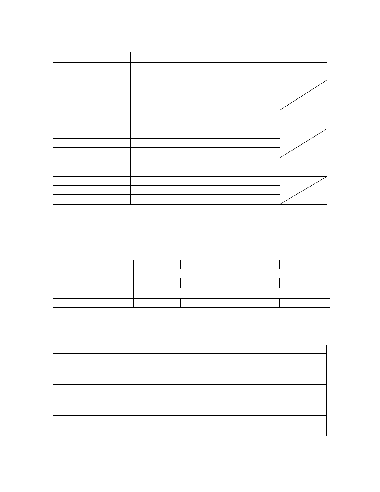
■One-Control Operation Setting Table
400L
Item
Single
Parallel connection
Series
connection
400L
400L×2
400L×3
400L+800L
400L×4
400L+800L×2
400L+400L+
800L×2
400L+800L×3
400L+400L
400W
800W
1200W
1600W
2000W
2400W
2800W
800W
Voltage
setting
SLOW
10mV
FAST
1V
Range
0V-82V
Min.displaydigit
10mV
Current
setting
SLOW
10mA
100mA
90mA
80mA
100mA
60mA
70mA
10mA
FAST
1A
10A
9A
8A
10A
6A
7A
1A
Range
0A-41A
0A-82A
0A-123A
0A-164A
0A-205A
0A-246A
0A-287A
0A-41A
Min.displaydigit
10mA
100mA
10mA
Power
setting
SLOW
10W
100W
99W
100W
100W
96W
98W
10W
FAST
100W
1000W
990W
1000W
1000W
960W
980W
100W
Range
10W-410W
20W-820W
30W-1230W
40W-1640W
50W-2050W
60W-2460W
70W-2870W
10W-410W
Min.displaydigit
1W
OVP
setting
SLOW
100mV
FAST
10V
Range
1V-84V
Min.displaydigit
10mV
OCP
setting
SLOW
100mA
200mA
300mA
400mA
500mA
600mA
700mA
100mA
FAST
10A
20A
30A
40A
50A
60A
70A
10A
Range
1A-42A
2A-84A
3A-126A
4A-168A
5A-210A
6A-252A
7A-294A
1A-42A
Min.displaydigit
10mA
100mA
10mA
Rating of PSF-1200L, please refer to Chapter 12.

11
800L
Item
Single
parallel connection
Series
connection
800L
800L×2
800L×3
800L×4
800L+800L
800W
1600W
2400W
3200W
1600W
Voltage
setting
SLOW
10mV
FAST
1V
Range
0V-82V
Min.displaydigit
10mV
Current
setting
SLOW
10mA
100mA
90mA
80mA
10mA
FAST
1A
10A
9A
8A
1A
Range
0A-82A
0A-164A
0A-246A
0A-328A
0A-82A
Min.displaydigit
10mA
100mA
10mA
Power
setting
SLOW
10W
100W
99W
100W
10W
FAST
100W
1000W
990W
1000W
100W
Range
10W-820W
20W-1640W
30W-2460W
40W-3280W
10W-820W
Min.displaydigit
1W
OVP
setting
SLOW
100mV
FAST
10V
Range
1V-84V
Min.displaydigit
10mV
OCP
setting
SLOW
100mA
200mA
300mA
400mA
100mA
FAST
10A
20A
30A
40A
10A
Range
1A-84A
2A-168A
3A-252A
4A-336A
1A-84A
Min.displaydigit
10mA
100mA
10mA
In series connection, the output voltage is twice as high as that of the master unit.
In parallel connection, the minimum digit of current display is 100mA.
In some model combinations, the resolution of current setting is different from the minimum digit
of current display and the display may not be changed by clicking the mouse button once.
Rating of PSF-1600L, please refer to Chapter 12.
This manual suits for next models
5
Table of contents
Other TEXIO Power Supply manuals

TEXIO
TEXIO PSW Series Owner's manual

TEXIO
TEXIO PDS20-10A User manual

TEXIO
TEXIO PPX Series Owner's manual

TEXIO
TEXIO PBW Series User manual

TEXIO
TEXIO PS-A Series User manual

TEXIO
TEXIO PSF-400H User manual

TEXIO
TEXIO PA10-5B User manual

TEXIO
TEXIO PR-A Series User manual

TEXIO
TEXIO PU6-200 User manual

TEXIO
TEXIO PW8-3AQP User manual


