TEXIO PBW Series User manual

表紙
User Manual
Programmable DC Regenerative Power Supply
PBW Series
PBW-502H
PBW-502HB
PBW-103HP
PBW-103HS

Warranty
Thank you for purchasing our measuring instrument.
Please read this instruction manual (hereinafter referred to as this instruction
manual) carefully to the end so that you can fully demonstrate the performance of
this instrument before using it. I would like to express my gratitude. Please keep
this manual in a safe place.
Please keep your purchase statement (delivery note, receipt, etc.) in a safe place
as it will serve as your warranty card.
If you have any questions regarding after-sales service or products, please contact
our service center.
Guarantee
Our measuring instruments will be repaired free of charge for one
year from the date of purchase for failures that occur during
normal use.
Even within the warranty period, repair will be charged in the
following cases.
1. Failure or damage caused by fire, natural disaster,
abnormal voltage, etc.
2. Improper repair, adjustment, or modification.
3. Failure or damage caused by improper handling.
4. If the failure is caused by a cause other than this product.
5. If you do not present your purchase details.
This warranty is valid only in Japan.
If a product sold in Japan is brought overseas and breaks down, it will basically be
repaired in Japan.
Even during the warranty period, you will be responsible for the transportation
costs to our company.
There are items marked with in this manual. This mark of his is an
important note for the safety of the customer who uses the instrument and for
protecting the instrument from destruction and damage. Please read it carefully
and use it correctly.

■About a trademark, a registered trademark
TEXIO is our product brand in industrial electronics. In addition, the
company name and the brand name mentioned in this instruction manual
are the trademark or the registered trademark of each company or group in
each country and region.
■About this instruction manual
When copying the part or all of contents of this instruction manual, seek the
copyright holder.
In addition, the specifications of the product and the contents of this
instruction manual are subject to change without notice for improvement.
■About export
This instrument is a model for exclusive use in Japan. Before taking this
product out of the country or exporting it, please consult with us, each sales
office, or our agency (dealer).
■About hardware and firmware versions.
The contents described in this document correspond to PBW series
hardware version 1.0 and firmware version 1.9.1008.2000 or higher.

Table of Contents
Chapter 1 Overview .............................................................1
1-1.Outline of PBW series ................................................1
1-1-1.Series list.............................................................1
1-1-2.
Operating Range
................................................3
1-1-3.Features..............................................................6
1-1-4.Accessories and options......................................6
1-2.Part Names and Functions.........................................7
1-2-1.Front Panel..........................................................7
1-2-2.Rear Panel ..........................................................8
1-3.LCD Display .............................................................10
1-3-1.Screen configuration..........................................10
1-3-2.Common operation display contents.................. 11
1-3-3.INITIALIZE Window...........................................14
1-3-4.WAIT Window....................................................14
1-3-5.RUN Screen......................................................15
1-3-6.ERROR Window................................................16
1-3-7.USER SETTING window...................................17
1-3-8.
Setting hierarchy
..............................................18
Chatper 2 Wiring................................................................19
2-1.AC Input/Protective Earth Terminal Block.................19
2-2.DC output terminal block..........................................21
Chapter 3 Basic Operation................................................23
3-1.Protection value setting............................................23
3-2.Slew rate setting.......................................................25
3-3.DC output resistance setting.....................................26
3-4.Setting of the control mode.......................................28

3-5.Command value/limit value setting...........................29
3-6.RUN / STOP Switching.............................................32
3-7.Error Reset...............................................................33
Chapter 4 Series-Parallel Operation.................................34
4-1.Series/Parallel Setting mode ....................................34
4-2.Series/Parallel Preparations.....................................35
4-2-1.
Series
-
Parallel Wiring
......................................35
4-2-2.
Series/Parallel Setting Procedure
....................37
Chapter 5 Various Settings ...............................................43
5-1.Interface Selection....................................................43
5-2.Console Setting........................................................44
5-2-1.LCD backlight adjustment..................................44
5-2-2.Panel display direction.......................................45
5-3.CAN setting..............................................................46
5-3-1.CAN Config .......................................................46
5-3-2.CAN Communication.........................................47
5-4.LAN Setting..............................................................50
5-4-1.LAN Config........................................................50
5-4-2.LAN Communication..........................................51
5-5.DIO ........................................................................54
5-5-1.DIO terminal......................................................54
5-5-2.
DIO Function Setting
........................................56
Chapter 6 Product Information .........................................58
6-1.Device information....................................................58
6-2.License Information..................................................59
6-3.Firmware Update......................................................60
6-4.Initialization Setting ..................................................63
Chapter 7 Others................................................................65
7-1.Troubleshooting........................................................65

7-2.Error indication.........................................................67
Chapter 8 Specifications...................................................73
8-1.General Specifications..............................................73
8-2.Terminal Specifications.............................................74
8-3.Electrical Specifications............................................74
8-4.Set value specification..............................................76
8-4-1.
Control mode setting specifications
.................76
8-4-2.
Protective Value Setting Specifications
...........76
8-4-3.
Command value setting specifications
............77
8-4-4.
Limit value setting specification
.......................77
8-4-5.
Slew Rate Setting Specifications
.....................78
8-4-6.
DC Output Resistance Setting Specifications
.78
8-4-7.
Series/Parallel Setting Specifications
..............79
8-5.Dimensions ..............................................................80

I
USING THE PRODUCT SAFELY
■Preface
To use the product safely, read this instruction manual to the end.
Before using this product, understand how to correctly use it.
If you read this manual but you do not understand how to use it, please ask us or
your local dealer. After you read this manual, save it so that you can read it,
anytime as requied.
■Pictorial indication
This instruction manual and product show the warning and caution items required
to safely use the product. The following pictorial indication and warning character
indication are provided.
<Pictorial indication>
Some part of this product or the instruction manual may
shows this pictorial indication. In this case, if the
product is incorrectly used in that part, a serious
danger may be brought about on the user’s body or the
product.
To use the part with this pictorial indication, be sure to
refer to this instruction manual.
!Warning
If you use the product, ignoring this indication, you may
get killed or seriously injured. This indication shows
that the warning item to avoid the danger is provided.
!Caution
If you incorrectly use the product, ignoring this
indication, you may get slightly injured or the product
may be damaged. This indication shows that the
caution item to avoid the danger is provided.
Please be informed that we are not responsible for any damages to the user or to
the third person, arising from malfunctions or other failures due to wrong use of
the product or incorrect operation, except such responsibility for damages as
required by law.

II
USING THE PRODUCT SAFELY
!Warning
!Caution
■Do not remove the product’s covers and panels
Never remove the product’s covers and panels for any purpose.
Otherwise, the user’s electric shock or fire may be incurred.
■Warning on using the product
Warning items given below are to avoid danger to user’s body and life and avoid
the damage or deterioration of the product.
Use the product, observing the following warning and caution items.
■Warning items on power supply
●Power supply voltage
The rated power supply voltage of the product is 3-phase AC200V.
●Power cord
(Important) The attached power cord set can be used for this device
only.
●Protective fuse
If an input protective fuse is blown, the product does not operate. For a
product with external fuse holder, the fuse may be replaced. As for how to
replace the fuse, refer to the corresponding chapter in this instruction manual.
If no fuse replacement procedures are indicated, the user is not permitted to
replace it. In such case, keep the case closed and consult us or your local
dealer. If the fuse is incorrectly replaced, a fire may occur.

III
USING THE PRODUCT SAFELY
■Warning item on Grounding
If the product has the GND terminal on the front or rear panel surface, be sure to
ground the product to safely use it.
■Warnings on Installation environment
●Operating temperature and humidity
Use the product within the operating temperature indicated in the “rating”
temperature column. If the product is used with the vents of the product
blocked or in high ambient temperatures, a fire may occur.
Use the product within the operating humidity indicated in the “rating”
humidity column. Watch out for condensation by a sharp humidity change
such as transfer to a room with a different humidity. Also, do not operate the
product with wet hands. Otherwise, an electric shock or fire may occur.
●Use in gas
Use in and around a place where an inflammable or explosive gas or steam is
generated or stored may result in an explosion and fire. Do not operate the
product in such an environment.
Also, use in and around a place where a corrosive gas is generated or
spreading causes a serious damage to the product. Do not operate the
product in such an environment.
●Installation place
Avoid installing the product on inclined places or on places subject to
vibration. Otherwise, the product may slip or fall down to cause damages or
injury accidents.
■Do not let foreign matter in
Do not insert metal and inflammable materials into the product from its vent and
spill water on it. Otherwise, electric shock or fire may occur.
■Warning item on abnormality while in use
In abnormal situations, such as “smoke”, “fire”, “abnormal smell” or “irregular
noise” occur from the product while in use, stop using the product, turn off the
switch, and remove the power cord plug from the outlet. After confirming that no
other devices catch fire, ask us or your local dealer.

IV
USING THE PRODUCT SAFELY
■Input / Output terminals
Maximum input to terminal is specified to prevent the product from being
damaged. Do not supply input, exceeding the specifications that are indicated in
the "Rating" column in the instruction manual of the product.
Also, do not supply power to the output terminals from the outside.
Otherwise, a product failure is caused.
■Calibration
Although the performance and specifications of the product are checked under
strict quality control during shipment from the factory, they may be deviated
more or less by deterioration of parts due to their aging or others.
It is recommended to periodically calibrate the product so that it is used with its
performance and specifications stable.
For consultation about the product calibration, ask us or your local dealer.
■Daily Maintenance
When you clean off the dirt of the product covers, panels, and knobs, avoid
solvents such as thinner and benzene. Otherwise, the paint may peel off or
resin surface may be affected.
To wipe off the covers, panels, and knobs, use a soft cloth with neutral detergent
in it. During cleaning, be careful that water, detergent, or other foreign matters
do not get into the product.
If a liquid or metal gets into the product, an electric shock and fire are caused.
During cleaning, remove the power cord plug from the outlet.
Use the product correctly and safely, observing the above warning and caution
items. Because the instruction manual indicates caution items even in individual
items, observe those caution items to correctly use the product.
If you have any questions or concerns regarding the contents of this manual,
please contact our service center.

1
Chapter 1 Overview
This chapter describes the precautions for safe use of the product,
basic operation methods, and main major specifications. Please
read this manual carefully before using the product and always
keep it on hand.
1-1. Outline of PBW series
1-1-1. Series list
The representative models of the PBW series are listed below.
Throughout the user manual, the term “PBW” refers to all models
unless otherwise specified.
The PBW series can handle up to 100kW. For details, please
contact your dealer or our company.
Model
Rated
power
Output
current
Output
voltage
Remarks
PBW-502H
5kW
±30A
525 V
LAN CAN DIO standard
PBW-502HB
5kW
±30A
525 V
Booster (Slave operation
only, independent
operation not possible)
PBW-103HP
10kW
±60A
525 V
PBW-502H +
PBW-502HB parallel
model
LAN CAN DIO standard
PBW-103HS
10kW
±30A
1000 V
PBW-502H +
PBW-502H-B serial
model
LAN CAN DIO standard

2
About the PBW-502HB Booster
Overview
Booster is a device that operates as a SLAVE for
series-parallel operation.
Functional
restriction
SINGLE setting and operation are not possible
MASTER setting and operation are not possible
during series/parallel operation.
Licenses other than serial functions and DIO
functions cannot be granted.
Determination of
Booster machine
There is a sticker of Booster under the power
switch.
Product Info > On the About screen, the end of
M/N is B.
PBW-502HB
3
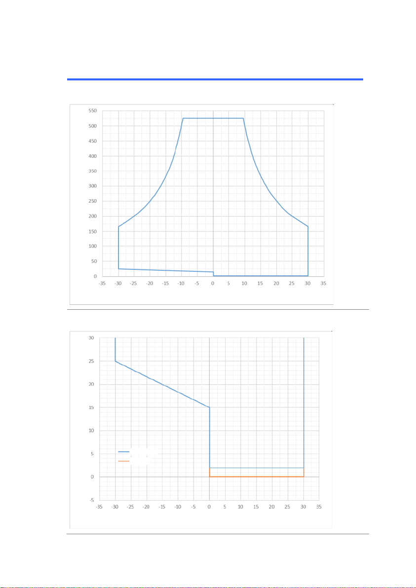
1-1-2.
Operating Range
PBW-502H
Voltage[V]
Current[A]
Undervoltage (30 V or less)
Voltage[V]
Current[A]
CV/CP mode
CC mode
4
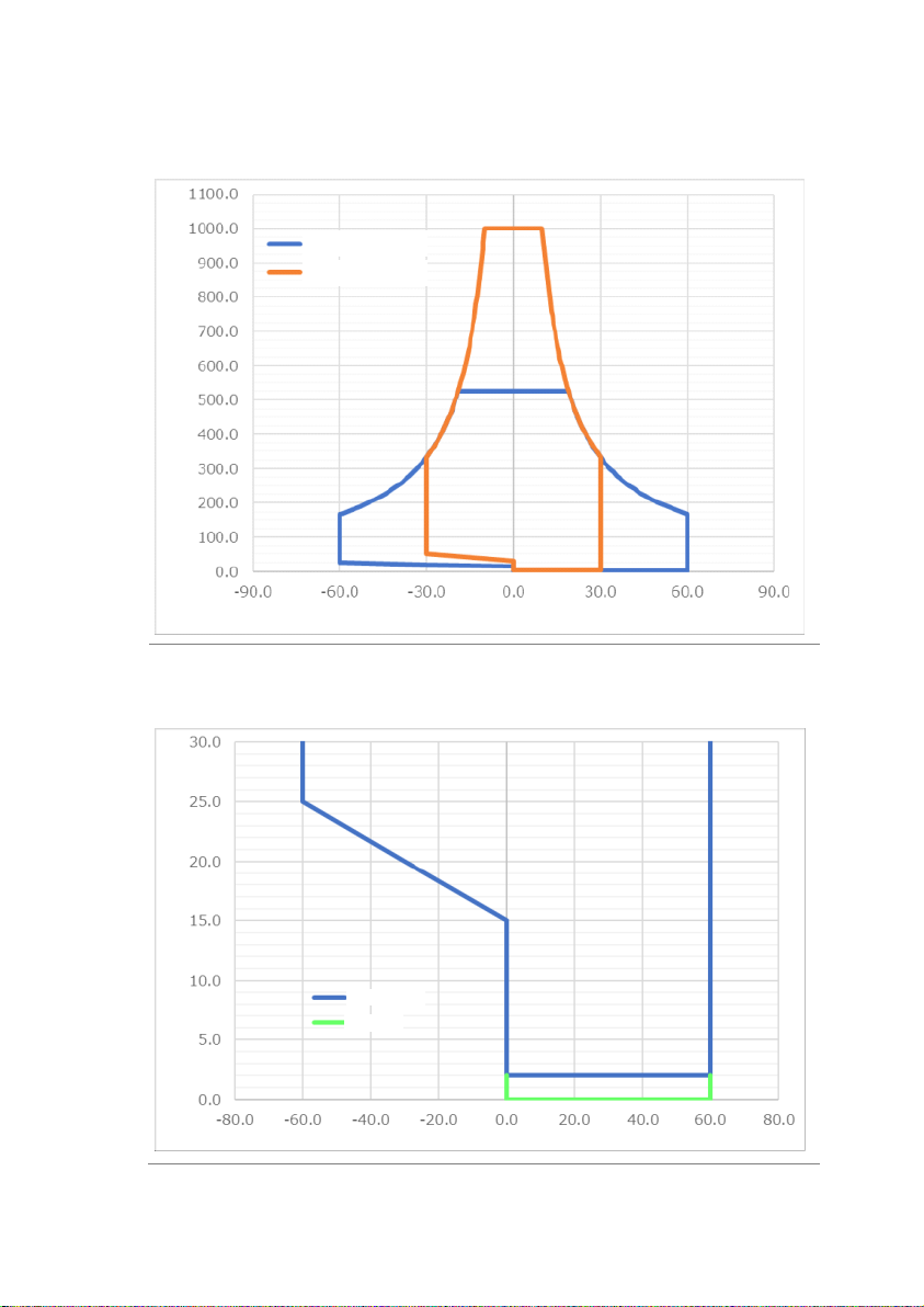
PBW-103HP (1 in series, 2 in parallel), PBW-103HS (2 in series, 1
in parallel)
Voltage[V]
Current[A]
1 in series, 2 in parallel
2 in series, 1 in parallel
PBW-103HP Undervoltage (30 V or less)
Voltage[V]
Current[A]
CV/CP mode
CC mode

5
PBW-103HS Undervoltage (30 V or less)
Voltage[V]
Current[A]
CV/CP mode
CC mode
The current in the AC → DC direction is assumed to be positive.
During series-parallel operation, the number of units is multiplied by
the same value.
The command value and limit value can be set regardless of the
operation range shown in the above figure. However, operation may
be impossible with a value set outside the operating range.
Low-voltage regeneration area (left side of figure above)
CV mode: Voltage rises because no current flows.
CC/CP mode: Operation is performed at a value smaller than the
command value as no current is allowed to flow.
Low Voltage Power Driving Area (right side of figure above)
This may not be stable due to conditions such as the UUT.

6
1-1-3. Features
1-1-4. Accessories and options
Before using the device, check the contents of the package to
ensure that all standard items are included.
Standard
accessories
Details
LAN cable
1
for sries/parallel communication
terminating resistor
1
for sries/parallel communication
Rack fixing bracket
1 set (2 pieces)
Mounting screws are included
on the side of the main unit
Housing fixing
bracket
1 set (4 pieces)
Mounting screws are included
on the side of the main unit
Features
Output voltage: 525 V Output current: ±30 A
5kW
Configurable up to 1000V, ±600A, 100kW with
series and parallel capabilities
Capable of operating as a power supply and
regenerative electronic load
Compact and lightweight by using SiC for
power devices
Equipped with color LCD
Function
Equipped with CV, CC, and CP control modes
Various protection functions
Adjustable slew rate
Adjustable output resistance
Equipped with serial and parallel master-slave
functions
External
interface
Equipped with LAN and CAN as standard
Equipped with external control DIO as standard

7
※AC input and output cables are not included.
※For PBW-103HP/HS, the housing fixing metal fittings are pre-
assembled.
1-2. Part Names and Functions
1-2-1. Front Panel
②③
④①
⑦⑥⑤⑧
No.
Name
Function
1
Main switch
Press “–” to Turn on the power
supply.
Press "O" to turn off the power
supply.
2
LCD
LCD display screen
3
Start/Stop
button
Start and stop operation of the
unit.This button illuminates green
during operation, red in abnormal
condition, and yellow during
standby for operation. It remains
unlit in other conditions.
4
Control
Knob
Rotate to set values and select
items.Turn the knob clockwise for
increases and counterclockwise
for decreases. Value settings or
item selections can be made by
pressing the knob (hereinafter
Entering).

8
5
Mode
button
Switches between CV, CC, CP,
and CR modes.
6
Shift button
Switches digits when manipulating
values.
7
MENU/
ESC Key
The key is used to switch setting
screen. It can also be used to
return to the previous screen.
8
Air inlet
This is an air inlet for cooling the
fan of the internal unit.
!Note
Never block the air intake.
1-2-2. Rear Panel
①③④⑤⑥⑦②⑧
No.
Name
Function
1
AC input terminal
This terminal block is
intended for connection to
the three-phase mains and
earthing to the ground.
2
DC Output
terminal block
DC Output terminal block
3
LINK IN
This connector is used to
connect the LAN cable or
terminating resistor when
performing series-parallel
operation.
4
LINK OUT

9
5
CAN
communication
port
This terminal block port is
used to control this device
via CAN communication.
6
Contact
input/output port
This terminal block is used
to control this device using
contact input/output.
7
LAN
communication
port
This connector is used to
control this device via LAN
communication. Also used
for updating and license
activation of this device.
8
Air inlet
This is an air inlet for cooling
the fan of the internal unit.
!Note
Never block the air intake.

10
1-3. LCD Display
Describes the display contents and operation methods of each
screen displayed on the LCD.
1-3-1. Screen configuration
USER SETTING
Protect
Upper : 545.0 V
[Current]
Upper : 33.00 A
Lower : - 33.00 A
Lower : - 5.0 V
Return
USER SETTING
Protect
Upper : 545.0 V
[Current]
Upper : 33.00 A
- 33.00 A
-
Return
Mode
Voltage
Current
Power
V.Output
CV
:Over Temperature
:Operation Ready
200.0V 0.0V
0.00A
0W
:Console I/F
(V.Output 200.0V)
120s
WAIT
Mode
Voltage
Current
Power
V.Output
CV STOP
:Over Temperature
:Operation Ready
200.0V 0.0V
0.00A
0W
:Console I/F
(V.Output 200.0V)
Mode
Voltage
Current
Power
V.Output
CV
:Over Temperature
:Operation Ready
200.0V 200.0V
15.00A
3000W
:Console I/F
(V.Output 200.0V)
RUN
Mode
Voltage
Current
Power
CV
0.0V
0.00A
0W
ERROR
Error Code
:0xFFFFFFFF+FF
Duplicated error.
Please refer to
the manual.
Series ID :1
Parallel ID :10
Reset
-> Push Enter
USER SETTING
Slew Rate
Protect
Resistance
Interface
Multiple
Product Info
USER SETTING
Protect
[Voltage]
Upper : 545 .0 V
[Current]
Return
Enter
MENU
/ESC
SETTING
INITIALIZE
WAIT
STOP ERROR
RUN
Each setting screen
OUTPUT
WAIT 完了
Start finished
MENU
/ESC Detect
anomalies
Enter
Lower : -3 .0 V
Upper : 33 .00 A
Lower : -33 .00 A
►
►
►
►
►
►
►
►
This manual suits for next models
4
Table of contents
Other TEXIO Power Supply manuals

TEXIO
TEXIO PAR-A Series User manual

TEXIO
TEXIO PDS20-10A User manual

TEXIO
TEXIO PW8-3AQP User manual

TEXIO
TEXIO PR-A Series User manual

TEXIO
TEXIO PU6-200 User manual

TEXIO
TEXIO PFR-100M250 Manual

TEXIO
TEXIO PSF-1200L User manual

TEXIO
TEXIO PFR-100 SERIES Owner's manual

TEXIO
TEXIO PS-A Series User manual

TEXIO
TEXIO PA10-5B User manual


