TEXIO PW8-3AQP User manual

INSTRUCTION MANUAL
PW-A SERIES MULTI-OUTPUT DC STABILIZED
POWER SUPPLY UNITS
PW-A SERIES
PW8-3AQP PW8-3ATP PW8-5ADPS
PW16-2ATP PW16-5ADP PW18-1.3AT(S)
PW18-1.8AQ PW18-2ATP PW18-3AD
PW18-3ADP PW24-1.5AQ PW26-1AT(S)
PW36-1.5AD PW36-1.5ADP
OPTIONAL INTERFACE UNITS FOR
PW-A SERIES
IF-41RS IF-41GU IF-41USB
© PRINTED IN JAPAN B68-0014-00


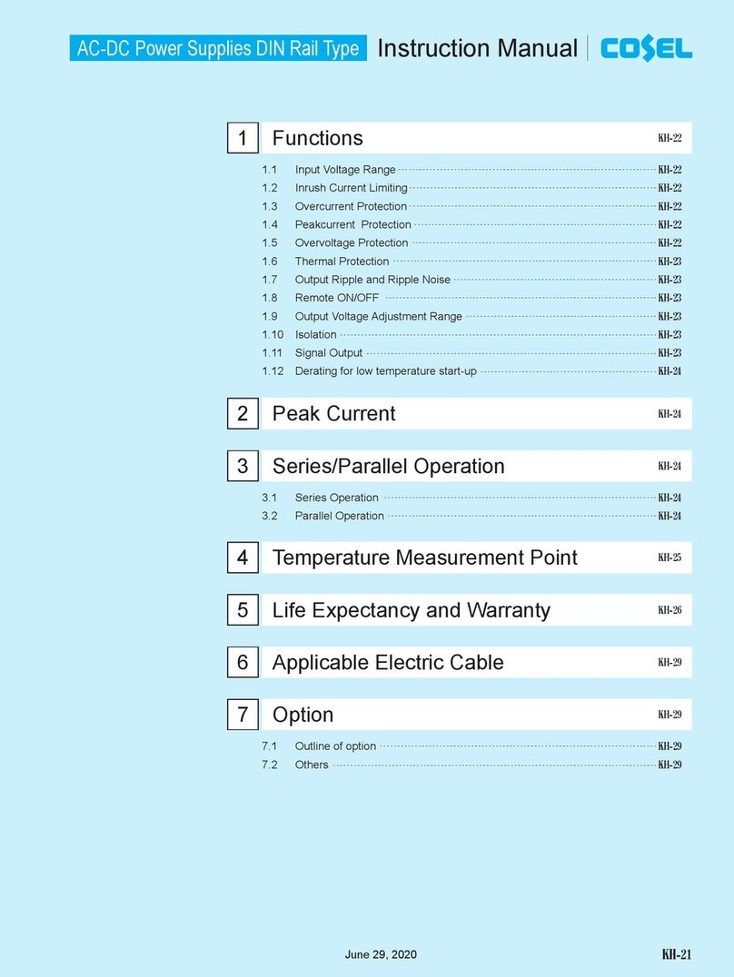
CONTENTS
USING THE PRODUCT SAFELY.......................................................................................................Ⅰ-Ⅳ
1. PW-A SERIES .............................................................................................................................. 1
1-1. About This Manual.........................................................................................................................1
1-2. Outline of Product..........................................................................................................................1
1-3. Features ........................................................................................................................................1
1-3-1. PW-A power supply unit..........................................................................................................1
1-3-2. IF-41RS(Option)....................................................................................................................2
1-3-3. IF-41GU(Option)....................................................................................................................2
1-3-4. IF-41USB(Option)..................................................................................................................2
1-4. Accessories ...................................................................................................................................2
2. SPECIFICATIONS........................................................................................................................ 3
3. INSTRUCTIONS ON USE ..........................................................................................................19
3-1. Checking Source Voltage ............................................................................................................19
3-2. Connecting AC Cable ..................................................................................................................19
3-3. Precautions for Connecting Output Terminals..............................................................................19
3-4. Installation Environments.............................................................................................................19
4. PANELS...................................................................................................................................... 20
4-1. Front Panel..................................................................................................................................20
4-2. Rear Panel...................................................................................................................................23
4-3. Bottom Plate................................................................................................................................24
5. GENERAL INSTRUCTIONS....................................................................................................... 25
5-1. Output Terminals of Each Channels and Key Switches...............................................................25
5-2. Turning On Power........................................................................................................................27
5-2-1. Display when power is turned on..........................................................................................27
5-2-2. Initial setting when power os turned on.................................................................................28
5-3. Overheat Alarm (OHA).................................................................................................................28
5-4. Changing Souce Voltage.............................................................................................................29
5-5. Connecting Loads........................................................................................................................30
6. FUNCTIONS AND OPERATION PROCEDURES...................................................................... 31
6-1. Basic Operations .........................................................................................................................31
6-1-1. Set value and output value display .......................................................................................31
6-1-2. Voltage setting procedures....................................................................................................31
6-1-3. Current setting procedures ...................................................................................................31
6-1-4. Fine adjustment of voltage (or current) .................................................................................31
6-2. Output Functions .........................................................................................................................32

6-2-1. Method of turning on or off the output with the MAIN OUTPUT key......................................32
6-2-2. Method of turning on or off the output with the OUTPUT SELECT key.................................32
6-3. Delay Functions...........................................................................................................................32
6-3-1. Setting delay continue ON/OFF............................................................................................33
6-3-2. Setting normal delay/reverse delay with output off................................................................33
6-3-3. Setting delay time .................................................................................................................33
6-3-4. Turing on output with delay function......................................................................................34
6-3-5. Turing on output with delay function......................................................................................34
6-4. Tracking Function ........................................................................................................................36
6-4-1. Selecting channel..................................................................................................................36
6-4-2. Selecting tracking mode........................................................................................................36
6-4-3. Using tracking function..........................................................................................................37
6-5. Memory Function.........................................................................................................................38
6-5-1. Storing preset voltage/current values....................................................................................38
6-5-2. Recalling preset values.........................................................................................................38
6-5-3. Storing values in preset memory in MAIN OUTPUT key on mode........................................39
6-5-4. Copying preset values ..........................................................................................................39
6-5-5. Storing setting of each key....................................................................................................39
6-6. Usage of KEYLOCK/LOCAL Key.................................................................................................40
6-7. Usage of Remote Sensing Function (PW18-1.3ATS, PW26-1ATS & PW8-5ADPS only).................41
7. EXTERNAL CONTACT CONTROL............................................................................................ 42
7-1. Outline of Functions.....................................................................................................................42
7-2. Specifications of External Contact Control Connector .................................................................42
7-3. Operation Procedures..................................................................................................................42
7-3-1. Turning on/off MAIN OUTPUT key through external contacts...............................................43
7-3-2. Selecting PRESET 1 key to PRESET 4 key through external contacts.................................43
7-3-3. Detecting OHA signal............................................................................................................43
7-3-4. Inputting alarm signal through external contacts...................................................................43
7-3-5. Inputting several alarms through external contacts...............................................................43
8. APPLICATION EXAMPLES ....................................................................................................... 44
8-1. Series Output of PW18-1.8AQ (four-channel power supply unit).................................................44
8-2. Series Output of PW18-1.3AT (three-channel power supply unit)................................................45
9. REMOTE CONTROL.................................................................................................................. 46
9-1. Connecting IF-41RS....................................................................................................................46
9-1-1. Remote control using computer............................................................................................47
9-1-2. Master operation...................................................................................................................48
9-1-3. Remote control using RT-63 .................................................................................................49
9-1-4. Remote control using GP-620...............................................................................................49
9-2. Connecting IF-41GU/IF-41USB...................................................................................................50
9-2-1. Remote control through GP-IB (IF-40GU only).....................................................................50
9-2-2. Control through USB.............................................................................................................51

9-2-3. Connecting IF-41GU/IF-41USB local bus.............................................................................51
9-3. Setting Addresses........................................................................................................................52
9-3-1. Addresses.............................................................................................................................52
9-3-2. Setting addresses.................................................................................................................52
9-3-3. Address setting range and set value.....................................................................................52
9-4. Transmission and Reception Procedures Using IF-41RS (without using GP-620) ......................53
9-4-1. Message structure ................................................................................................................54
9-4-2. Precautions for sending or receiving message .....................................................................56
9-4-3. Specifying slave machine as talker from master unit ............................................................57
9-4-4. Acknowledge or negative acknowledge to slave units..........................................................57
9-5. Usage of IF-41GU/USB...............................................................................................................59
9-5-1. Usage of GPIBの(IF-41GU only)...........................................................................................59
9-5-2. Usage of USB.......................................................................................................................59
9-5-3. Status bytes ..........................................................................................................................60
9-5-4. Application configuration.......................................................................................................60
9-6. Sending Commands (through GP-IB or USB) .............................................................................61
9-6-1. Precautions for sending commands......................................................................................61
9-6-2. Selecting unit to be controlled...............................................................................................61
9-7. Details of Commands ..................................................................................................................62
9-7-1. Setting unit to be controlled ..................................................................................................62
9-7-2. Setting voltage or current......................................................................................................62
9-7-3. Activating or deactivating tracking function...........................................................................63
9-7-4. Selecting output to be used in tracking mode .......................................................................63
9-7-5. Selecting tracking mode (voltage/current variation)..............................................................63
9-7-6. Setting tracking voltage/current.............................................................................................64
9-7-7. MAIN OUTPUT KEYのON/OFF............................................................................................65
9-7-8. Turning on/off OUTPUT SELECT key...................................................................................65
9-7-9. Turning on/off output delay function......................................................................................65
9-7-10. Setting output delay time ....................................................................................................66
9-7-11. Selecting display contents...................................................................................................66
9-7-12. Selecting preset memory ....................................................................................................66
9-7-13. Status output request..........................................................................................................66
9-7-14. ID output request ................................................................................................................67
9-7-15. Local setting........................................................................................................................67
9-7-16. Local lockout.......................................................................................................................67
9-7-17. Disabling or enabling service request.................................................................................67
9-7-18. Storing set data...................................................................................................................68
9-7-19. Checking controlled unit......................................................................................................68
9-7-20. Checking connected slave unit ...........................................................................................68
9-7-21. Inquiry about optional board ID...........................................................................................68
9-7-22. Sending output voltage, output current or operation mode (Response to the ST0 command) ....69

9-7-23. Sending all preset values (Response to the ST1 command) ..............................................69
9-7-24. Sending all equipment statuses (Response to the ST2 command)..................................70
9-7-25. Sending ID data (Response to the ST3 command)..........................................................71
9-7-26. Sending output voltage, output current or operation mode (Response to the ST4 command) ....71
9-7-27. Sending all preset values (Response to the ST5 command) ..............................................71
9-7-28. Sending power supply data (Response to the PWID command) ........................................71
9-7-29. Sending address of controlled unit (IF-41GU/IF-41USB only) ............................................71
9-7-30. Sending addresses of all connected slave units (IF-41GU/IF-41USB only)........................72
9-7-31. Sending optional board ID (IF-41GU/IF-41USB only).........................................................72
9-7-32. Information of constant-voltage/constant-current mode......................................................72
9-7-33. Information of alarm status..................................................................................................72
9-7-34. Information about completion of storing the set data ..........................................................72
9-8. Command List .............................................................................................................................73
10. OPERATION FAILURES..........................................................................................................74
11. OUTSIDE DIMENSIONS ..........................................................................................................75

I
USING THE PRODUCT SAFELY
■ Preface
To use the product safely, read this user's guide to the end. Before using this product, understand
how to correctly use it.
If you read this manual but you do not understand how to use it, call the company or each sales
office that is indicated on the back cover of this user's guide. After you read this manual, save it so
that you can read it anytime as required.
■ Notes on reading this user's guide
◆ The contents of this user's guide include technical terms in part of their explanation.
If you do not understand those terms, do not hesitate to ask the company or each sales office.
■ Pictorial indication and warning character indication
This user's guide and product show the warning and caution items required to safely use
the product. The following pictorial indication and warning character indication are provided.
<Pictorial indication>
Some part of this product or the user's guide may show this pictorial
indication. In this case, if the product is incorrectly used in that part, a
serious danger may be brought about on the user's body or the
product.
To use the part with this pictorial indication, be sure to refer to this
user's guide.
< Warning character
indication>
WARNING
CAUTION
If you use the product, ignoring this indication, you may get killed or
seriously injured. This indication shows that the warning item to avoid
the danger is provided.
If you incorrectly use the product, ignoring this indication, you may get
slightly injured or the product may be damaged. This indication shows
that the caution item to avoid the danger is provided.

II
USING THE PRODUCT SAFELY
WARNING
■ Do not remove the product's covers and panels
Never remove the product's covers and panels for any purpose.
Otherwise, the user's electric shock or a fire may be incurred.
■ Warning on using the product
The warning items given below are to avoid danger to the user's body and life and avoid the
damage and deterioration of the product.
Use the product, observing the following warning and caution items.
■ Warning about Input Power
- Be sure to use the product within the source voltage rating marked on the product. Disobedience
to this warning may result in a fire. The rated source voltage of this product is AV 100V to 240V
(voltage fluctuation: within ±10%), single-phase. (AC250V max.)
-Use the AC power cable supplied with the product. Using another power cable may result in electric
shocks, electrocution or a fire. If the supplied AC power cable is damaged, stop using it and
contact your dealer or our distributor. Using the product with the damaged AC power cable may
result in electric shocks, electrocution or a fire.
-The product will not run if the input protection fuse has blown. The protection fuse is built in the
product and cannot be replaced by the user. If it has blown, contact your dealer or our distributor
without opening the case. Our serviceman will replace it. The user must not attempt to replace the
fuse at his/her discretion. Disobedience to this warning may result in electric shocks, electrocution
or a fire. IF 100V or 120V is to be changed into 220V or 230V, power cord need to be changed.
■ About Grounding
- Be sure to connect the ground wire of the three-wire power cable supplied with the product (or the
ground terminal of the three-pole plug of the cable) to the earth. The chassis of the product is
grounded to the GND.
■ Warning about Installation Conditions
- Use the product in the operation temperature range shown in the manual. Do not use the product
with the vent holes blocked or in a high ambient temperature. Disobedience to this warning may
result in a fire.
- Use the product in the operation humidity range shown in the manual. When moving it to a room at
different humidity, pay attention to dew condensation due to rapid humidity change. Do not handle
the product with wet hands. Disobedience to this warning may result in electric shocks,
electrocution or a fire.
- Do not use the product in or around a place where combustible gas, explosive gas or vapor is
produced or stored. Disobedience to this warning may result in explosion or a fire. Do not use the
product in or around a place where corrosive gas is produced or accumulated. Disobedience to this
warning may result in serious damages to the product.
- Do not put metallic or combustible objects or pour water into the product through the vent holes,
etc. Disobedience to this warning may result in electric shocks, electrocution or a fire.
■ Warning about Errors in Operation
- If the product products smoke, fire or odor in operation, stop using the product, turn it off, and
disconnect the AC power cable from the AC outlet. Make sure that the fire hasn’t spread to other
equipment, then contact your dealer or our distributor.

III
USING THE PRODUCT SAFELY
CAUTION
■ Caution about Installation Condition
- If this product is used in a place with much electrical noises, it may malfunction. Be sure to ground this
product using the GND terminal of the 3-core power cable or the GND lead wire of a 3P-2P conversion
plug, if used, when it is necessary to use this product in a place with much electrical noises.
■ External Control I/O Connector
- The external control I/O connector has its maximum rating. The maximum rating must not be
exceeded. Input or output over the maximum rating may result in damages to the product.
■Before Long-Term Unemployment
- If the product is to be unused for a long period of time, disconnect the AC power cable from the
AC outlet.
■Calibration
- The product has been inspected under strict quality control before shipment. It is, however, subject
to change in the performances due to aged deterioration of parts. To maintain its performances for
long, we recommend that it should be calibrated periodically. For calibration, please contact your
dealer or our distributor.
■Daily Maintenance
- Do not use thinner, benzine or other solvents to clean the case, panels, knobs, etc. of the
product. Such solvent may separate the coating or deteriorate the resin surface.
- Clean the case, panels, knobs, etc. lightly with soft cloth moistened with neutral detergent.
- Before cleaning the product, disconnect the power plug from the AC outlet. Be careful not
to put water, detergent or other foreign matters into the product.

IV
USING THE PRODUCT SAFELY
CAUTION
■ Input/output terminal
Maximum input to the input terminals is specified to prevent the product from being damaged.
Do not supply input, exceeding the specifications that are indicated in the "Rating" or "Caution on
use" column in the user's guide of the product. Otherwise, a product failure is caused.
Also, do not supply power to the output terminals from the outside.
Otherwise, a product failure is caused.
■When the product is left unused for a long time
Be sure to remove the power plug from the outlet.
(Calibration)
Although the performance and specifications of the product are checked under strict quality control
during shipment from the factory, they may slightly change because of secular changes in its parts.
It is recommended to periodically calibrate the product so that it is used with its performance and
specifications stable. For consultation about the product calibration, call the dealer or the
company or each sales office where you bought the product.
(Daily maintenance)
When you clean off the dirt of the product covers, panels, and knobs, avoid solvents such as
thinner and benzene. Otherwise, paint may peel off or the resin surface may be affected.
To wipe off the covers, panels, and knobs, use a soft cloth with neutral detergent in it.
During cleaning, be careful that water, detergents, and other foreign matters do not get into the
product.
If a liquid or metal gets into the product, an electric shock and fire are caused.
During cleaning, remove the power cord plug from the outlet.
Use the product correctly and safely, observing the above warning and caution items.
Because the user's guide indicates caution items even in individual items, observe those
caution items to correctly use the product.
If you have questions or comments about the content of the user's guide, call the
company's sales office.

1
1. PW-A SERIES
1-1. About This Manual
This manual applies to the following PW-A series power supply units and optional interface units.
PW-A series:
PW18-1.8AQ,PW18-1.3AT,PW18-3AD,PW36-1.5AD
PW18-3ADP,PW18-2ATP,PW16-5ADP,PW8-3ATP
PW26-1AT,PW36-1.5ADP,PW18-1.3ATS,PW26-1ATS
PW8-3AQP、PW16-2ATP、PW24-1.5AQ、PW8-5ADPS
Optional interface units for the PW-A series:
IF-41RS,IF-41GU,IF-41USB
Note:The IF-41 series are compatible with all models of the PW-Apower supply unit series shown
above. The previous IF-40 series are not compatible with the PW8-3AQP, PW16-2ATP,
PW8-5ADPS and PW24-1.5AQ.
Use the IF-41 series, not IF-40 series, for the PW8-3AQP, PW16-2ATP, PW8-5ADPS and
PW24-1.5AQ.
“YB” models with built-in factory options
1-2. Outline of Product
The PW-A series are dropper type multi-output DC stabilized power supply units. With the tracking,
delay and four-point preset functions, each unit has a wide variety of applications. The optional
interface boards IF-41GU, IF-41RS and IF-41USB are built in the PW-A series and interface with
computers. Each PW-A series power supply unit connected with a computer is connectable with
another PW-A series power supply unit through the local bus, allowing construction of an intelligent
power supply system. It is possible to control all power supply units in the system and read back the
current and voltage values from the computer.
1-3. Features
1-3-1. PW-Apower supply unit
- The tracking function may vary the voltage and current of each channel at he same ratio (or by an
absolute value). It may be set for each output. It is possible to vary all outputs simultaneously.
- The delay function may turn on or off a specific channel after a delay of specified time in the
multi-output mode. It is possible to set the delay time of each channel independently between 0 to
10 seconds.
- With a CPU and four preset memory units, the PW-Apower supply unit may store preset voltage
and current of each channel. This function enables easy switching of the voltage (or current).
- The output voltage and current are displayed on seven-segment, four-digit red LED indicators. Fine
adjustment functions are provided for accurate setting.
- It is possible to turn on or off each channel independently. The LED clearly indicates in which
status, CV or CC, each channel is.
- It is possible to select PRESET 1 to PRESET 4, turn on or off MAIN OUTPUT key, detect an OHA
alarm and input an alarm through the external contacts.
- The YB option is available. This factory option lowers the output voltage quickly when output is
turned off with no load or light load. "YB" is added to the product code of a model with this option.
(Example: PW18-1.8AQYB)
- The PW18-1.3ATS and PW26-1ATS have remote sensing terminals in the C channel.
The PW8-5ADPS have remote sensing terminals in both channels.
Use the remote sensing terminal to compensate for voltage drop caused by the wires.

2
1-3-2. IF-41RS(Option)
- The PW-A power supply unit with a built-in IF-41RS is possible to remote-control when it is
connected with a computer by RS-232C. The computer controlling the PW-Apower supply unit is
called the master unit, and the controlled PW-Apower supply unit is called the slave unit. It is
possible to connect a maximum of four slave units, which are connected with one another with
modular cables.
- It is also possible to specify equipment other than a computer as the master unit. If the PW-A
power supply unit is specified as the master unit, operating the master unit causes the other four
PW-Apower supply units to execute the same operation. (Master operation)
- It is also possible to specify the GP-620 (our GP-IB adapter) or RT-63 (our remote controller) as
the master unit, which may remote-control the PW-Apower supply unit.
- The PW-A power supply unit is compatible with the PWR series (our power supply unit). It is
possible to construct a system containing PWR series power supply unit(s).
1-3-3. IF-41GU(Option)
- The IF-41GU is an optional board, which features higher transmission rate than the IF-41RS and
may control more power supply units simultaneously.
- It is connected with a computer through GP-IB or USB.A maximum of fourteen or thirty-two units
may be connected directly with a computer through GP-IB or USB, respectively.
- It is also possible to construct a large-scale system if thirty-one PW-Apower supply units are
connected with a PW-A power supply unit directly connected with a computer using two sets of
twisted pair cables and these units are remote-controlled.
1-3-4. IF-41USB(Option)
- The IF-41USB is an option board with the USB connector and local bus, which have the same
functions of those of the IF-41GU.
- It allows the user to construct a system at lower cost than using the IF-41GU.
1-4. Accessories
<PW-Apower supply unit>
AC power cable: 1
Instruction manual: 1
Lead wires with connectors for external contact control: 1
PW18-1.3ATS,PW26-1ATS、only: Lead wires with sensing terminals: 2
PW8-5ADPS: Lead wires with sensing terminals: 4
<IF-41RS,IF-41GU and IF-41USB>
Simple manual: 1
Lead wire with Y terminal for FG connection: 1
FG – control line connector: 1

3
2. SPECIFICATIONS
Specifications of PW18-1.8AQ
Item A Channel B Channel C Channel D Channel
Output voltage 0V to +18V 0V to -18V 0V to +8V 0V to -6V
Voltage setting
resolution 10mV 1mV
±(0.5%SET+20mV)±(0.5%SET+5mV)
Voltage setting
accuracy 23℃±5℃、after 30-minute aging
Output current 0A to +1.8A 0A to -1.8A 0Ato +2A 0A to -1A
Current setting
resolution 1mA
±(1%SET+5mA)
Current setting
accuracy 23℃±5℃、after 30-minute aging
CV characteristics 1mV
Input variation (For ±10% variation of source voltage)
2mV
Load variation (for 0% to 100% variation)
0.5mV
Ripple noise Measured in the RMS method using 5Hz to 1MHz signals
Transient response 50μs(TYP)
Temperature
coefficient 60ppm/℃:(at rated output voltage)
CC characteristics 2mA
Input variation (For ±10% variation of source voltage)
5mA
Load variation (For 0% to 100%variation)
1.5mA
Ripple noise Measured in the RMS method using 5Hz to 1MHz signals
Temperature
Coefficient 150ppm/℃: (at rated output current)
Voltage & current indication
Voltage indicator 4-digit red LEDs, lowest digit: 10mV 4-digit red LEDs, lowest digit: 1mV
±(0.5%rdg+20mV)/10mV ±(0.5%rdg+5mV)/1mV
Voltage indication
accuracy & resolution At 23℃±5℃、after 30-minute aging
Current indicator 4-digit red LEDs, lowest digit: 1mA
±(1%rdg+5mA)/1mA
Current indication
accuracy & resolution At 23℃±5℃、after 30-minute aging
Voltage & current
Indication range -2.5%FS to +102.5%FS/0%FS to +102.5%FS
Common Common
source voltage AC100V AC115V AC120V AC200V AC220V AC230V
Power consumption Approx.
191W/
255VA
Approx.
191W/
255VA
Approx.
200W/
260VA
Approx.
191W/
255VA
Approx.
210W/
280VA
Approx.
191W/
255VA

4
Specifications of PW18-1.3AT(S) C channel of ATS with Remote sensing terminals.
Item A Channel B Channel C Channel
Output voltage 0V to +18V 0V to -18V 0V to+6V
Voltage setting
resolution 10mV 1mV
±(0.5%SET+20m V)±(0.5%SET+5mV)
Voltage setting
accuracy At 23℃±5℃、after 30-minute aging
Output current 0A to +1.3A 0A to -1.3A 0A to +5A
Current setting
resolution 1mA
±(1%SET+5mA)
Current setting
accuracy At 23℃±5℃、after 30-minute aging
CV characteristics 1mV
Input variation (For ±10% variation of source voltage)
2mV
Load variation (For 0% to 100% variation)
0.5mV
Ripple noise Measured in the RMS method using 5Hz to 1MHz signals.
Transient response 50μs(TYP)
Temperature
coefficient 60 ppm/℃(at rated output voltage)
CC characteristics 2mA
Input variation (For ±10% variation of source voltage)
5mA
Load variation (For 0% to 100% variation)
1.5mA
Ripple noise Measured in the RMS method using 5Hz to 1MHz signals.
Temperature
coefficient 150 ppm/℃(at rated output current)
Voltage & current indication
Voltage indicator 4-digit red LEDs, lowest digit: 10mV 4-digit red LEDs,
lowest digit: 1mV
±(0.5%rdg+20mV)/10mV ±(0.5%rdg+5mV)/
1mV
Voltage indication
accuracy & resolution At 23℃±5℃、after 30-minute aging
Current indicator 4-digit red LEDs, lowest digit: 1mA
±(1%rdg+5mA)/1mA
Current indication
accuracy & resolution At 23℃±5℃、after 30-minute aging
Voltage & current
Indication range -2.5%FS to +102.5% FS/0%FS to +102.5%
common Common Independent
source voltage AC100V AC115V AC120V AC200V AC220V AC230V
Power consumption Approx.
179W/
230VA
Approx.
179W/
230VA
Approx.
187W/
242VA
Approx.
179W/
230VA
Approx.
197W/
255VA
Approx.
179W/
230VA

5
Specifications of PW18-3AD
Item A Channel B Channel
Output voltage 0V to +18V 0V to -18V
Voltage setting
resolution 10mV
±(0.5%SET+20mV)
Voltage setting
accuracy At 23℃±5℃、after 30-minute aging
Output current 0A to +3A 0A to -3A
Current setting
resolution 1mA
±(1%SET+5mA)
Current setting
accuracy At 23℃±5℃、after 30-minute aging
CV characteristics 1mV
Input variation (For ±10% variation of source voltage)
2mV
Load variation (For 0% to 100% variation)
0.5mV
Ripple noise Measured in the RMS method using 5Hz to 1MHz signals.
Transient response 50μs(TYP)
Temperature
coefficient 60 ppm/℃(at rated output voltage)
CC characteristics 2mA
Input variation (For ±10% variation of source voltage)
5mA
Load variation (For 0% to 100% variation)
1.5mA
Ripple noise Measured in the RMS method using 5Hz to 1MHz signals.
Temperature
coefficient 150 ppm/℃(at rated output current)
Voltage & current indication
Voltage indicator 4-digit red LEDs, lowest digit: 10mV
±(0.5%rdg+20mV)/10mV
Voltage indication
accuracy & resolution At 23℃±5℃、after 30-minute aging
Current indicator 4-digit red LEDs, lowest digit: 0.1mA
±(1%rdg+5mA)/1mA
Current indication
accuracy & resolution At 23℃±5℃、after 30-minute aging
Voltage & current
indication range -2.5%FS to +102.5% FS/0%FS to +102.5%
Common Common
source voltage AC100V AC115V AC120V AC200V AC220V AC230V
Power consumption Approx.
213W/
278VA
Approx.
213W/
278VA
Approx.
223W/
285VA
Approx.
213W/
278VA
Approx.
34W/
305VA
Approx.
213W/
278VA

6
Specifications of PW36-1.5AD
Item A Channel B Channel
Output voltage 0V to +36V 0V to -36V
Voltage setting
resolution 10mV
±(0.5%SET+20mV)
Voltage setting
accuracy At 23℃±5℃、after 30-minute aging
Output current 0A to +1.5A 0A to -1.5A
Current setting
resolution 1mA
±(1%SET+5mA)
Current setting
accuracy At 23℃±5℃、after 30-minute aging
CV characteristics 1mV
Input variation (For ±10% variation of source voltage)
2mV
Load variation (For 0% to 100% variation)
0.6mV
Ripple noise Measured in the RMS method using 5Hz to 1MHz signals.
Transient response 50μs(TYP)
Temperature
coefficient 60ppm/℃(at rated output voltage)
CC characteristics 2mA
Input variation (For ±10% variation of source voltage)
5mA
Load variation (For 0% to 100% variation)
1.5mA
Ripple noise Measured in the RMS method using 5Hz to 1MHz signals.
Temperature
coefficient 150 ppm/℃(at rated output current)
Voltage & current indication
Voltage indicator 4-digit red LEDs, lowest digit: 10mV
±(0.5%rdg+20mV)/10mV
Voltage indication
accuracy & resolution At 23℃±5℃、after 30-minute aging
Current indicator 4-digit red LEDs, lowest digit: 1mA
±(1%rdg+5mA)/1mA
Current indication
accuracy & resolution At 23℃±5℃、after 30-minute aging
Voltage & current
indication range -2.5%FS to +102.5% FS/0%FS to +102.5%FS
Common Common
source voltage AC100V AC115V AC120V AC200V AC220V AC230V
Power consumption Approx.
189W/
255VA
Approx.
189W/
255VA
Approx.
193W/
265VA
Approx.
189W/
255VA
Approx.
208W/
280VA
Approx.
189W/
255VA

7
Specifications of PW18-3ADP
Item A Channel B Channel
Output voltage 0V to +18V 0V to +18V
Voltage setting
resolution 10mV
±(0.5%SET+20mV)
Voltage setting
accuracy At 23℃±5℃、after 30-minute aging
Output current 0A to +3A 0A to +3A
Current setting
resolution 1mA
±(1%SET+5mA)
Current setting
accuracy At 23℃±5℃、after 30-minute aging
CV characteristics 1mV
Input variation (For ±10% variation of source voltage)
2mV
Load variation (For 0% to 100% variation)
0.5mV
Ripple noise Measured in the RMS method using 5Hz to 1MHz signals.
Transient response 50μs(TYP)
Temperature
coefficient 60 ppm/℃(at rated output voltage)
CC characteristics 2mA
Input variation (For ±10% variation of source voltage)
5mA
Load variation (For 0% to 100% variation)
1.5mA
Ripple noise Measured in the RMS method using 5Hz to 1MHz signals.
Temperature
coefficient 150 ppm/℃(at rated output current)
Voltage & current indication
Voltage indicator 4-digit red LEDs, lowest digit: 10mV
±(0.5%rdg+20mV)/10mV
Voltage indication
accuracy & resolution At 23℃±5℃、after 30-minute aging
Current indicator 4-digit red LEDs, lowest digit: 1mA
±(1%rdg+5mA)/1mA
Current indication
accuracy & resolution At 23℃±5℃、after 30-minute aging
Voltage & current
indication range -2.5%FS to +102.5% FS/0%FS to +102.5%FS
Common Common
source voltage AC100V AC115V AC120V AC200V AC220V AC230V
Power consumption Approx.
213W/
278VA
Approx.
213W/
278VA
Approx.
223W/
285VA
Approx.
213W/
278VA
Approx.
234W/
305VA
Approx.
213W/
278VA

8
Specifications of PW18-2ATP
Item A Channel B Channel C Channel
Output voltage 0V to +36V 0V to +18V 0V to +8V
Voltage setting
resolution 10mV 1mV
±(0.5%SET+20mV)±(0.5%SET+5mV)
Voltage setting
accuracy At 23℃±5℃、after 30-minute aging
Output current 0A to +1A 0A to +2A 0A to +2A
Current setting
resolution 1mA
±(1%SET+5mA)
Current setting
accuracy At 23℃±5℃、after 30-minute aging
CV characteristics 1mV
Input variation (For ±10% variation of source voltage)
2mV
Load variation (For 0% to 100% variation)
0.6mV 0.5mV
Ripple noise Measured in the RMS method using 5Hz to 1MHz signals.
Transient response 50μs(TYP)
Temperature
coefficient 60 ppm/℃(at rated output voltage)
CC characteristics 2mA
Input variation (For ±10% variation of source voltage)
5mA
Load variation (For 0% to 100% variation)
1.5m A
Ripple noise Measured in the RMS method using 5Hz to 1MHz signals.
Temperature
coefficient 150 ppm/℃(at rated output current)
Voltage & current indication
Voltage indicator 4-digit red LEDs, lowest digit: 10mV 4-digit red LEDs,
lowest digit: 1mV
±(0.5%rdg+20m V)/10mV ±(0.5%rdg+5mV)/
1mV
Voltage indication
accuracy & resolution At 23℃±5℃、after 30-minute aging
Current indicator 4-digit red LEDs, lowest digit: 1mA
±(1%rdg+5m A)/1mA
Current indication
accuracy & resolution At 23℃±5℃、after 30-minute aging
Voltage & current
indication range -2.5%FS to +102.5% FS/0% FS to +102.5%FS
Common Common Independent
source voltage AC100V AC115V AC120V AC200V AC220V AC230V
Power consumption Approx.
178W/
242VA
Approx.
178W/
242VA
Approx.
186W/
250VA
Approx.
178W/
242VA
Approx.
196W/
270VA
Approx.
178W/
242VA

9
Specifications of PW16-5ADP
Item A Channel B Channel
Output voltage 0V to +6V 0V to+16V
Voltage setting
resolution 1mV 10mV
±(0.5%SET+5mV)±(0.5%SET+20mV)
Voltage setting
accuracy At 23℃±5℃、after 30-minute aging
Output current 0A to +3A 0A to +5A
Current setting
resolution 1mA
±(1%SET+5mA)
Current setting
accuracy At 23℃±5℃、after 30-minute aging
CV characteristics 1mV
Input variation (For ±10% variation of source voltage)
2mV
Load variation (For 0% to 100% variation)
0.5mV
Ripple noise Measured in the RMS method using 5Hz to 1MHz signals.
Transient response 50μs(TYP)
Temperature
coefficient 60 ppm/℃(at rated output voltage)
CC characteristics 2mA
Input variation (For ±10% variation of source voltage)
5mA
Load variation (For 0% to 100% variation)
1.5mA
Ripple noise Measured in the RMS method using 5Hz to 1MHz signals.
Temperature
coefficient 150 ppm/℃(at rated output current)
Voltage & current indication
Voltage indicator 4-digit red LEDs, lowest digit: 1mV 4-digit red LEDs, lowest digit: 10mV
±(0.5%rdg+5mV)/1mV ±(0.5%rdg+20mV)/10mV
Voltage indication
accuracy & resolution At 23℃±5℃、after 30-minute aging
Current indicator 4-digit red LEDs, lowest digit: 1mA
±(1%rdg+5mA)/1mA
Current indication
accuracy & resolution At 23℃±5℃、after 30-minute aging
Voltage & current
indication range -2.5%FS to +102.5% FS/0%FS to +102.5%FS
Common Common
source voltage AC100V AC115V AC120V AC200V AC220V AC230V
Power consumption Approx.
212W/
265VA
Approx.
212W/
265VA
Approx.
222W/
282VA
Approx.
212W/
265VA
Approx.
233W/
300VA
Approx.
212W/
265VA

10
Specifications of PW8-3ATP
Item A Channel B Channel C Channel
Output voltage 0V to +8V 0V to +8V 0V to +18V
Voltage setting
resolution 1mV 10mV
±(0.5%SET+5mV)±(0.5%SET+20mV)
Voltage setting
accuracy At 23℃±5℃、after 30-minute aging
Output current 0A to +3A 0A to +3A 0A to +1.5A
Current setting
resolution 1mA
±(1%SET+5mA)
Current setting
accuracy At 23℃±5℃、after 30-minute aging
CV characteristics 1mV
Input variation (For ±10% variation of source voltage)
2mV
Load variation (For 0% to 100% variation)
0.5mV
Ripple noise Measured in the RMS method using 5Hz to 1MHz signals.
Transient response 50μs(TYP)
Temperature
coefficient 60 ppm/℃(at rated output voltage)
CC characteristics 2mA
Input variation (For ±10% variation of source voltage)
5mA
Load variation (For 0 to 100% variation)
1.5mA
Ripple noise Measured in the RMS method using 5Hz to 1MHz signals.
Temperature
coefficient 150 ppm/℃(at rated output current)
Voltage & current indication
Voltage indicator 4-digit red LEDs, lowest digit: 1mV 4-digit red LEDs,
lowest digit: 10mV
±(0.5%rdg+5mV)/1mV ±(0.5%rdg+20mV)/
10mV
Voltage indication
accuracy & resolution At 23℃±5℃、after 30-minute aging
Current indicator 4-digit red LEDs, lowest digit: 1mA
±(1%rdg+5mA)/1mA
Current indication
accuracy & resolution At 23℃±5℃、after 30-minute aging
Voltage & current
indication range -2.5%FS to +102.5% FS/0%FS to +102.5%FS
Common Common Independent
source voltage AC100V AC115V AC120V AC200V AC220V AC230V
Power consumption Approx.
183W/
240VA
Approx.
183W/
240VA
Approx.
191W/
253VA
Approx.
183W/
240VA
Approx.
201W/
270VA
Approx.
183W/
240VA
This manual suits for next models
15
Table of contents
Other TEXIO Power Supply manuals
TEXIO
TEXIO PSW Series User manual
TEXIO
TEXIO PSF-1200L User manual
TEXIO
TEXIO PA10-5B User manual
TEXIO
TEXIO PAR-A Series User manual
TEXIO
TEXIO PPX Series Owner's manual
TEXIO
TEXIO PD18-10AD User manual
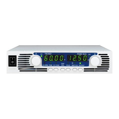
TEXIO
TEXIO PU Series User manual
TEXIO
TEXIO PU6-100 User manual

TEXIO
TEXIO PSF-400H User manual
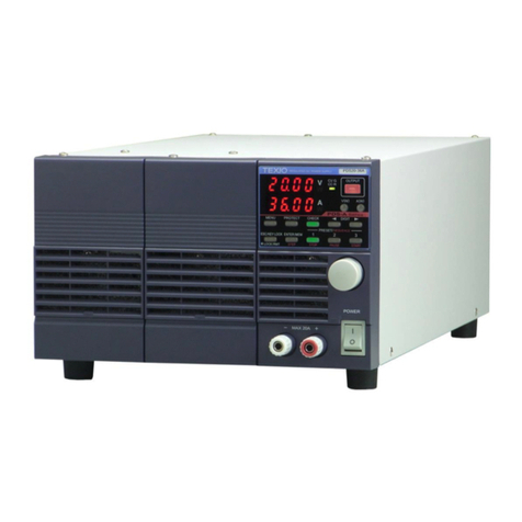
TEXIO
TEXIO PDS20-10A User manual
Popular Power Supply manuals by other brands
Speedotron
Speedotron 2403CX instruction manual
INNOVATIVE CIRCUIT TECHNOLOGY
INNOVATIVE CIRCUIT TECHNOLOGY HELIOS ICT DIN Series instruction manual
Spektrum
Spektrum PowerSafe AR9100 user guide

BT Lab Systems
BT Lab Systems Mini 500 manual
Spid Elektronik
Spid Elektronik PS-01 manual

VTOMAN
VTOMAN Jump 1500 backup battery user manual
